Voltammetry and Polarography Lecture 3 1 Why a

- Slides: 37
Voltammetry and Polarography Lecture 3 1
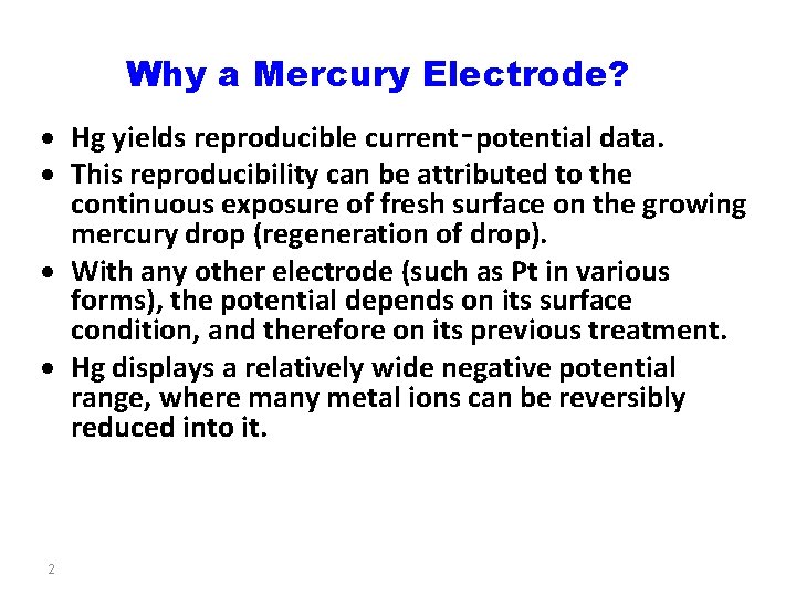
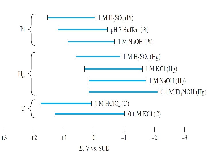
Why a Mercury Electrode? Hg yields reproducible current‑potential data. This reproducibility can be attributed to the continuous exposure of fresh surface on the growing mercury drop (regeneration of drop). With any other electrode (such as Pt in various forms), the potential depends on its surface condition, and therefore on its previous treatment. Hg displays a relatively wide negative potential range, where many metal ions can be reversibly reduced into it. 2
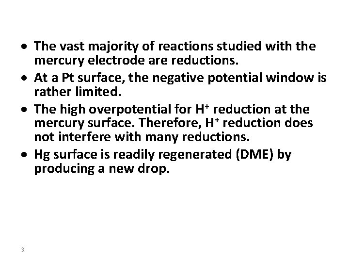
The vast majority of reactions studied with the mercury electrode are reductions. At a Pt surface, the negative potential window is rather limited. The high overpotential for H+ reduction at the mercury surface. Therefore, H+ reduction does not interfere with many reductions. Hg surface is readily regenerated (DME) by producing a new drop. 3
4
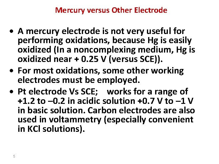
Mercury versus Other Electrode A mercury electrode is not very useful for performing oxidations, because Hg is easily oxidized (In a noncomplexing medium, Hg is oxidized near + 0. 25 V (versus SCE)). For most oxidations, some other working electrodes must be employed. Pt electrode Vs SCE; works for a range of +1. 2 to – 0. 2 in acidic solution +0. 7 V to – 1 V in basic solution. Carbon electrodes are also used in voltammetry (especially convenient in KCl solutions). 5
Mercury is toxic and slightly volatile, and spills are almost unavoidable. a good vacuum cleaner is a must. To remove residual mercury, add elemental zinc powder on the surface and dampen the powder with 5% aqueous H 2 S 04. Mercury dissolves in the zinc. After working the paste into contaminated areas with a sponge or brush, allow the paste to dry and then sweep it up. Discard the powder appropriately as contaminated mercury waste. 6
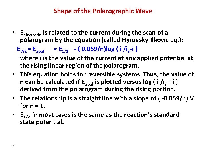
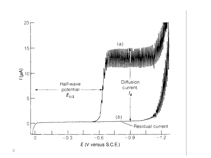
Shape of the Polarographic Wave • Eelectrode is related to the current during the scan of a polarogram by the equation (called Hyrovsky-Ilkovic eq. ): EWE = Eappl = E 1/2 - ( 0. 059/n)log ( i /id-i ) where i is the value of the current at any applied potential at the rising linear region of the polarogram. • This equation holds for reversible systems. Thus, the value of n can be calculated if Eappl is plotted versus log ( i /id - i ) derived from the polarogram during the rising portion. • The relationship is a straight line with a slope of ( -0. 059/n) V for n = 1. • E 1/2 in most cases is the same as the reaction’s standard state potential. 7
8
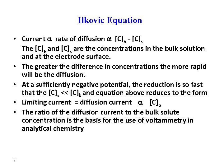
Ilkovic Equation • Current rate of diffusion [C]b - [C]s The [C]b and [C]s are the concentrations in the bulk solution and at the electrode surface. • The greater the difference in concentrations the more rapid will be the diffusion. • At a sufficiently negative potential, the reduction is so fast that the [C]s << [C]b and equation above reduces to the form • Limiting current = diffusion current [C]b • The ratio of the diffusion current to the bulk solute concentration is the basis for the use of voltammetry in analytical chemistry 9
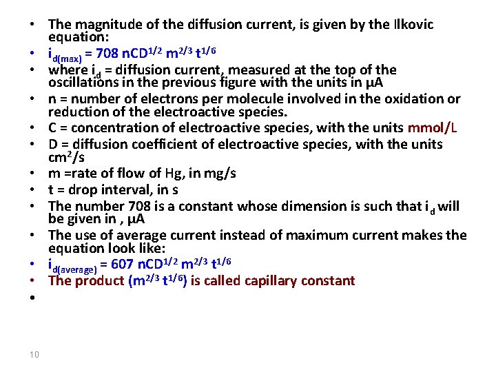
• The magnitude of the diffusion current, is given by the Ilkovic equation: • id(max) = 708 n. CD 1/2 m 2/3 t 1/6 • where id = diffusion current, measured at the top of the oscillations in the previous figure with the units in µA • n = number of electrons per molecule involved in the oxidation or reduction of the electroactive species. • C = concentration of electroactive species, with the units mmol/L • D = diffusion coefficient of electroactive species, with the units cm 2/s • m =rate of flow of Hg, in mg/s • t = drop interval, in s • The number 708 is a constant whose dimension is such that i d will be given in , µA • The use of average current instead of maximum current makes the equation look like: • id(average) = 607 n. CD 1/2 m 2/3 t 1/6 • The product (m 2/3 t 1/6) is called capillary constant • 10
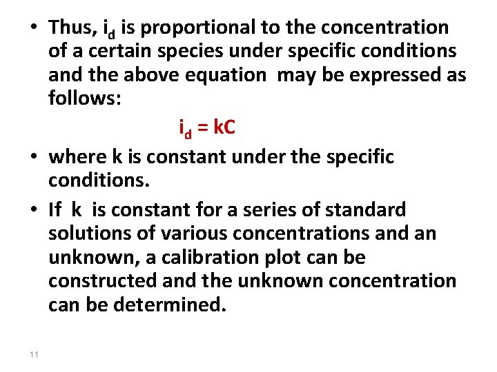
• Thus, id is proportional to the concentration of a certain species under specific conditions and the above equation may be expressed as follows: id = k. C • where k is constant under the specific conditions. • If k is constant for a series of standard solutions of various concentrations and an unknown, a calibration plot can be constructed and the unknown concentration can be determined. 11
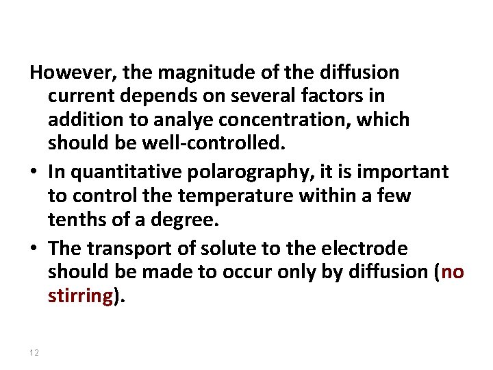
However, the magnitude of the diffusion current depends on several factors in addition to analye concentration, which should be well-controlled. • In quantitative polarography, it is important to control the temperature within a few tenths of a degree. • The transport of solute to the electrode should be made to occur only by diffusion (no stirring). 12
Supporting electrolyte • Current flow due to electrostatic attraction (or repulsion) of analyte ions by the electrode is reduced to a negligible level by the presence of a high concentration of supporting electrolyte. • Increasing concentrations of electrolyte reduces the net current, since the rate of arrival of cationic analyte at the negative DME surface is decreased. • Typically, a supporting electrolyte concentration 50‑ 100 times greater than the analyte concentration will reduce electrostatic transport of the analyte to a negligible level. 13
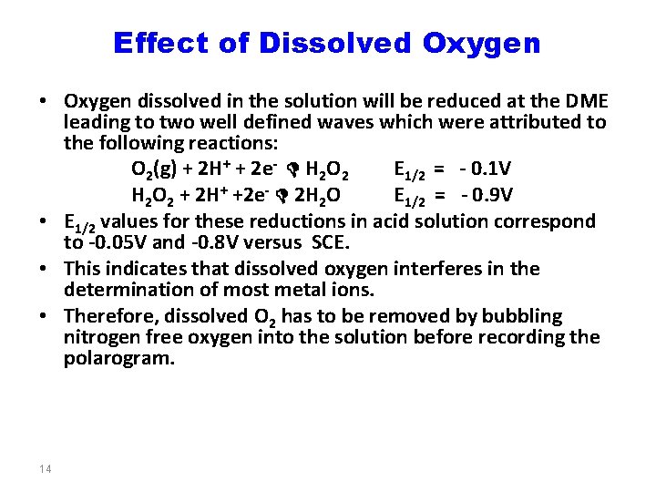
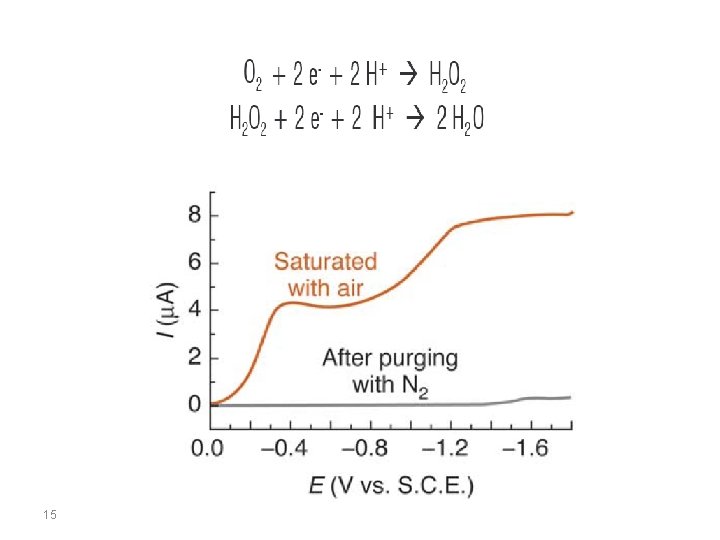
Effect of Dissolved Oxygen • Oxygen dissolved in the solution will be reduced at the DME leading to two well defined waves which were attributed to the following reactions: O 2(g) + 2 H+ + 2 e- D H 2 O 2 E 1/2 = - 0. 1 V H 2 O 2 + 2 H+ +2 e- D 2 H 2 O E 1/2 = - 0. 9 V • E 1/2 values for these reductions in acid solution correspond to -0. 05 V and -0. 8 V versus SCE. • This indicates that dissolved oxygen interferes in the determination of most metal ions. • Therefore, dissolved O 2 has to be removed by bubbling nitrogen free oxygen into the solution before recording the polarogram. 14
15
Residual Current • Even in the absence of analyte, a small current flows through an electrochemical cell. • This current, which is called the residual current, consists of two components: – a faradaic current due to the oxidation or reduction of trace impurities 16
– a charging current which is the current needed to charge or discharge the capacitor formed by the electrode surface‑solution interface. This is called the condenser current or charging current. – It is present in all voltammetric and polarographic experiments, regardless of the purity of reagents. – As each drop of mercury falls, it carries its charge with it to the bottom of the cell. The new drop requires more current for charging. 17
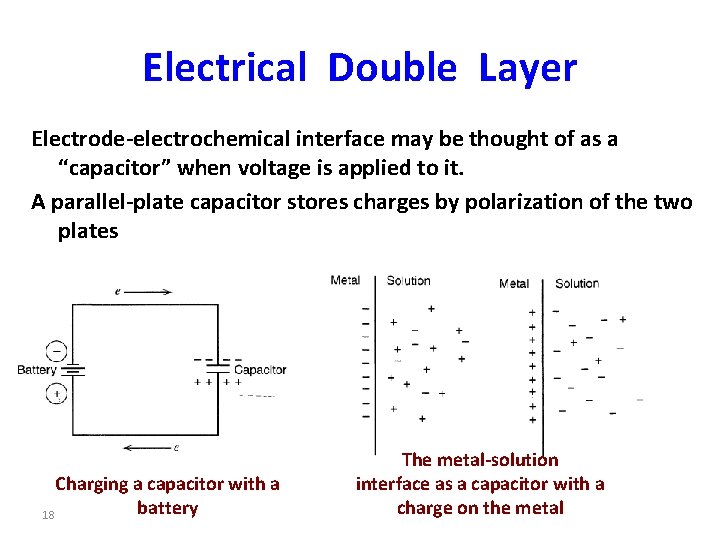
Electrical Double Layer Electrode-electrochemical interface may be thought of as a “capacitor” when voltage is applied to it. A parallel-plate capacitor stores charges by polarization of the two plates Charging a capacitor with a battery 18 The metal-solution interface as a capacitor with a charge on the metal
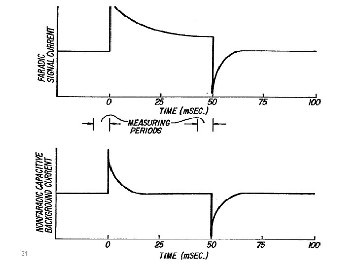
Faradaic Current and Double Layer Charging (Capacitive) Current The total measured current in polarography consists of two major components, the faradaic current due to the electrochemical reaction and the charging current. This charging current flows to charge the electrode-solution interfacial capacitor in response to the applied potential as well as to the area change. The charging current has the characteristic that it decays faster than the faradaic component, besides attaining almost zero value at the end of the drop. 19
To study the faradaic process and to deduce reaction mechanism or for analytical purposes, it is necessary to eliminate or compensate for the double layer charging current. The charging current depends on: 1. The changing area of the electrode with the growth of the drop 2. The change of potential with time (sweep rate) 3. It is essentially zero at the end of the drop life Therefore, reduce the charging current by: 1. Using a small sweep rate 2. Sample the current at the end of the drop life 20
21
The value of the polarographic charging current thus depends on the time change of the electrode area: It can be shown that: ic = K(d. A/dt), or ic t-1/3 Therefore, the charging current decreases with the lifetime of the drop. That is why the current is always sampled at the end of the drop life. 22
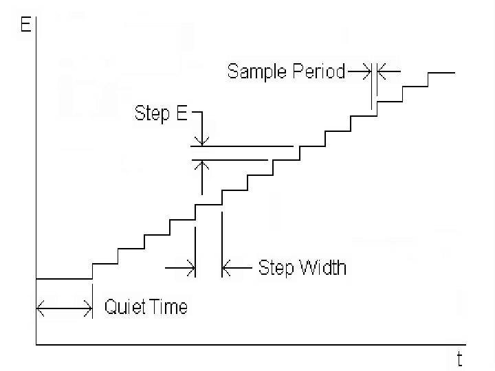
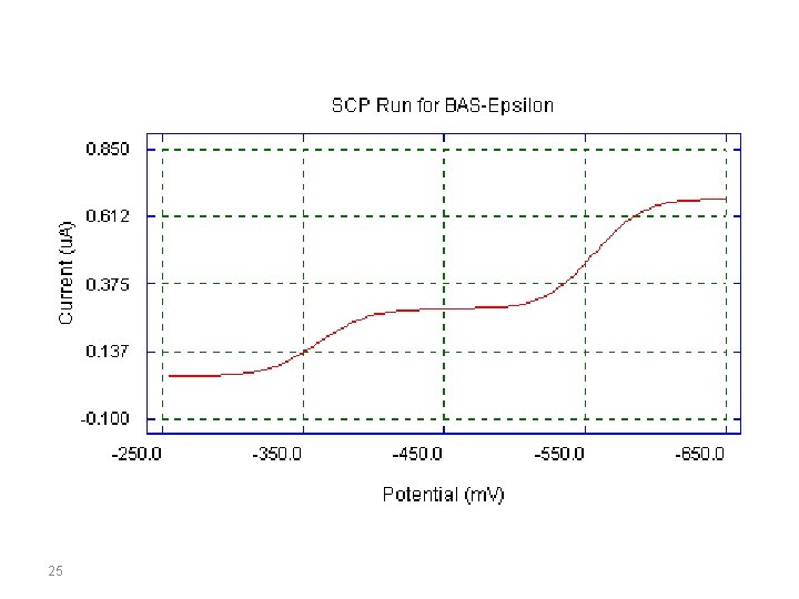
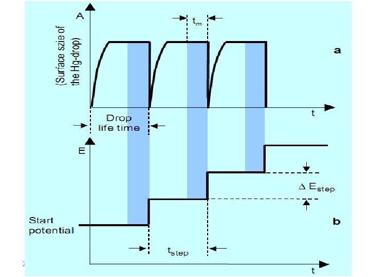
Sampled Current Polarography (SCP) • Sampled current polarograph (SCP) is a modification of the classical DC polarography experiment, and was designed to reduce the effect of the changing surface area of the mercury drop electrode. The potential wave form is shown in the following figure. The potential is varied in a series of steps, with the current sampled at the end of each step. 23
24
25
In digital instruments the direct current polarograms are no longer recorded with a linear potential alteration, but by using a staircase ramp as the excitation signal. In the measuring technique, the current (in the measuring time tm) is always measured at the end of a potential step (the potential ramp is synchronized with the drop life at the MDE), i. e. at a constant potential (part b) and at an electrode surface area that remains constant (part a); this reduces the contribution of the capacitive current to the measuring signal to a minimum. 26
27
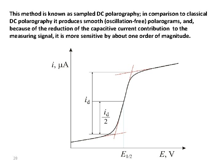
This method is known as sampled DC polarography; in comparison to classical DC polarography it produces smooth (oscillation-free) polarograms, and, because of the reduction of the capacitive current contribution to the measuring signal, it is more sensitive by about one order of magnitude. 28
Voltammetry The term voltammetry results from volt-am(père)-metry and should not be confused with voltametry – written with one m – which is described by IUPAC as being a controlledcurrent potentiometric titration. The terms polarography and voltammetry are frequently used in the reverse sense or are used inaccurately. We can view polarography as a special case of voltammetry, thus the developed theory of voltammetry, for most practical reasons, apply to polarography. 29
According to the IUPAC rules, the term polarography should always be used when the current-potential curve is recorded by using a liquid working electrode whose surface can be renewed periodically or continuously (e. g. by drops). Voltammetry includes all methods in which the current-potential measurements are made at stationary and fixed working electrodes (irrespective of their material composition), which makes the HMDE belongs to voltammetry!!!. 30
Voltammetric methods of Analysis Voltammetry comprises a group of electroanalytical methods in which information about the analyte is derived from measurement of current as a function of potential, under specified conditions that guarantees polarization of the working electrode. Generally, to enhance polarization, the working electrodes in voltammetry are microelectrodes that have surface areas from a few square millimeters at the most to, in some applications, only a few square micrometers. 31
A potential sweep is applied across an electrochemical cell, and the current flowing through the cell is measured as a function of potential. A plot of current as a function of applied potential is called a voltammogram (polarogram when a Hg drop is the working electrode), providing quantitative and qualitative information about the species involved in the oxidation or reduction reaction. 32
Voltammetric Measurements • Three electrode system potentiostat is used as a device that measures the current as a function of potential • Working electrodes used: Hg, Pt, Au, Ag, C or others • Reference electrode: SCE or Ag/Ag. Cl; • Auxiliary electrode: Pt wire 33
Current in Voltammetry • When an analyte is oxidized at the working electrode, a current passes electrons through the external electric circuitry to the auxiliary electrode. • This current flows from the auxiliary to the working electrode, where reduction of the solvent or other components of the solution matrix occurs. • The current resulting from redox reactions at the working and auxiliary electrodes is called a faradaic current. • Sign Conventions: A current due to the analyte's reduction is called a cathodic current and, by convention, is considered positive. Anodic currents are due to oxidation reactions and carry a negative value. 34
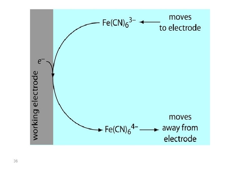
Influence of applied potential on the faradaic current • When the potential applied to the working electrode exceeds the reduction potential of the electroactive species, a reduction will take place at the electrode surface. • Thus, electroactive species diffuse from the bulk solution to the electrode surface and the reduction products diffuse from the electrode surface towards the bulk solution. This creates what is called the faradaic current. 35
36
• The magnitude of the faradaic current is determined by the rate of the resulting oxidation or reduction reaction at the electrode surface. • Two factors contribute to the rate of the electrochemical reaction: – the rate at which the reactants and products are transported to and from the surface of the electrode (mass transport) – the rate at which electrons pass between the electrode and the reactants and products in solution. (kinetics of electron transfer at the electrode surface) 37