Topics to discuss today Simple machines Compound machines





- Slides: 98
Topics to discuss today • • Simple machines Compound machines Lever Linkage Wedge Mechanical Advantage Inclined plane Screw
To do in class • Mechanical design is an important component of this class – how it relates to your project • What you want to learn? • What you plan to do?
• This material is easy and part of it you can read by yourself. • When you read it, please think how you can apply these ideas in practical robots. • Look also to internet to find who sells these and similar items that can be used in your robot
Conclusion on projects • Mechanical design is an important component of this class • This class is not only programming, you have to pay more attention to mechanical and interfacing aspects of robot design. • Robot programming is different from standard programming, it is a real time application programming.
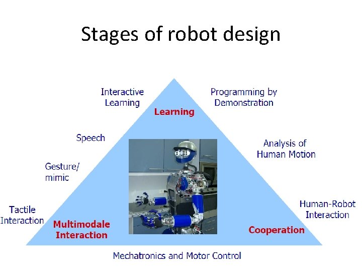
Stages of robot design
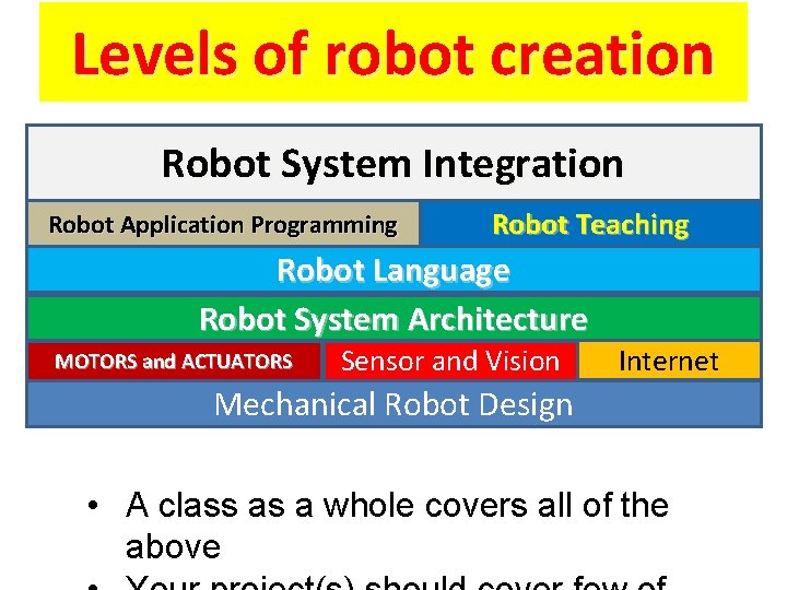
Levels of robot creation Robot System Integration Robot Application Programming Robot Teaching Robot Language Robot System Architecture MOTORS and ACTUATORS Sensor and Vision Internet Mechanical Robot Design • A class as a whole covers all of the above
Homework: Kinematic Model of the robot
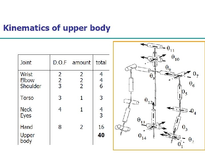
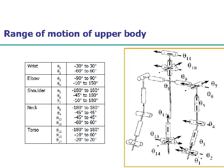
Part of your Homework • Create a model, as in the previous two slides, for your robot • Write all necessary data for torques, angles and length of arms etc.
Kinematics • The study of motion without regard to the forces or mass of the things moving. • Kinematic diagrams are scaled drawings symbolizing how mechanisms work. • We study robot kinematics in Fall • We study dynamics in Winter
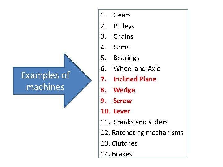
Examples of machines 1. Gears 2. Pulleys 3. Chains 4. Cams 5. Bearings 6. Wheel and Axle 7. Inclined Plane 8. Wedge 9. Screw 10. Lever 11. Cranks and sliders 12. Ratcheting mechanisms 13. Clutches 14. Brakes
Machines and Tools 1. Machines and tools are mechanical devices that work by transmitting or converting energy. 2. Machines are made up of a variety of mechanisms. 3. What are some examples of machines?
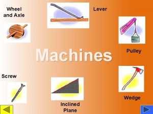
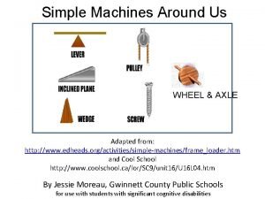
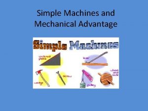
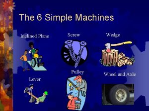
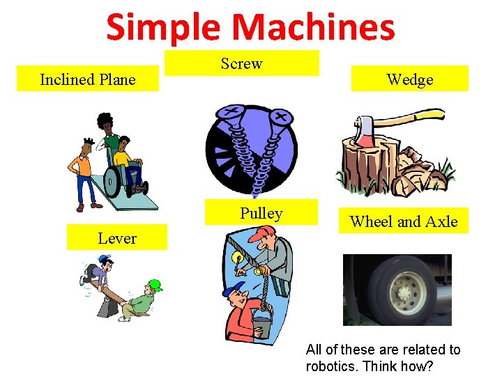
Simple Machines Inclined Plane Screw Pulley Lever Wedge Wheel and Axle All of these are related to robotics. Think how?
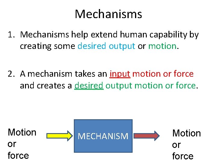
Mechanisms 1. Mechanisms help extend human capability by creating some desired output or motion. 2. A mechanism takes an input motion or force and creates a desired output motion or force. Motion or force MECHANISM Motion or force
Types of Motion • Common types of motion: – Linear – Reciprocal – Rotary – Oscillating All these have applications in
Definitions: Energy: Ability to do work Work Force * Distance = Force: A Push or a Pull
Linkages
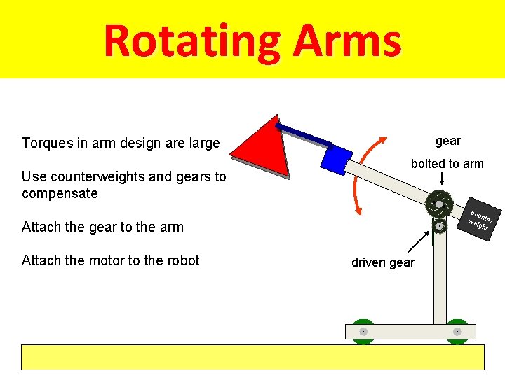
Rotating Arms gear Torques in arm design are large Use counterweights and gears to compensate bolted to arm Attach the motor to the robot motor Attach the gear to the arm driven gear cou n wei ter ght
Role of Linkages • Linkages transmit the motion or force to the desired output location. • Linkages: 1. change the direction of the force 2. Change the length of motion of the force 3. Split the motion and force over multiple paths
Levers
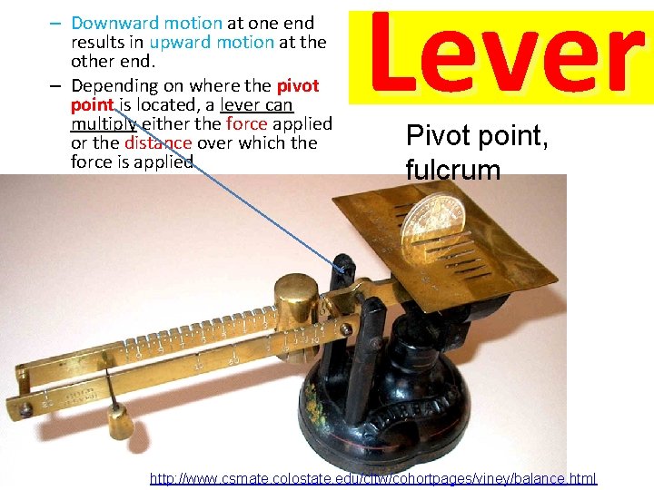
– Downward motion at one end results in upward motion at the other end. – Depending on where the pivot point is located, a lever can multiply either the force applied or the distance over which the force is applied Lever Pivot point, fulcrum http: //www. csmate. colostate. edu/cltw/cohortpages/viney/balance. html
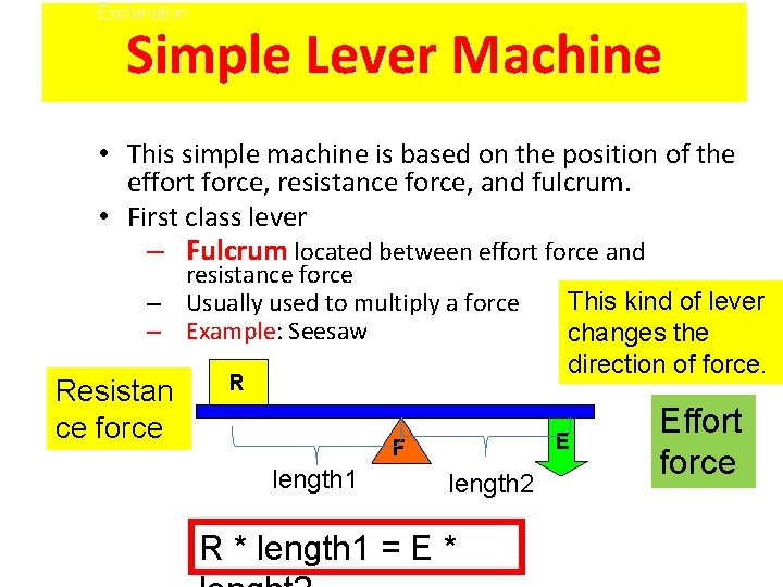
Explanation Simple Lever Machine • This simple machine is based on the position of the effort force, resistance force, and fulcrum. • First class lever – Fulcrum located between effort force and resistance force – Usually used to multiply a force – Example: Example Seesaw Resistan ce force R E F length 1 This kind of lever changes the direction of force. length 2 R * length 1 = E * Effort force
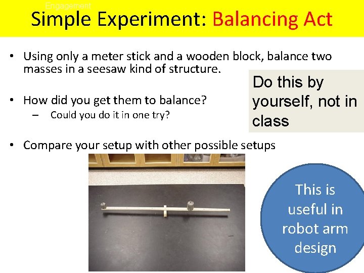
Engagement Simple Experiment: Balancing Act • Using only a meter stick and a wooden block, balance two masses in a seesaw kind of structure. • How did you get them to balance? – Could you do it in one try? Do this by yourself, not in class • Compare your setup with other possible setups This is useful in robot arm design
Exploration Simple Experiment: Balancing Act Lever Forces • Materials – – – Computer/calculator Force Probe 500 g mass String Meter stick Wooden Block We do such projects in High school robotics Do not discuss next 2 slides in class
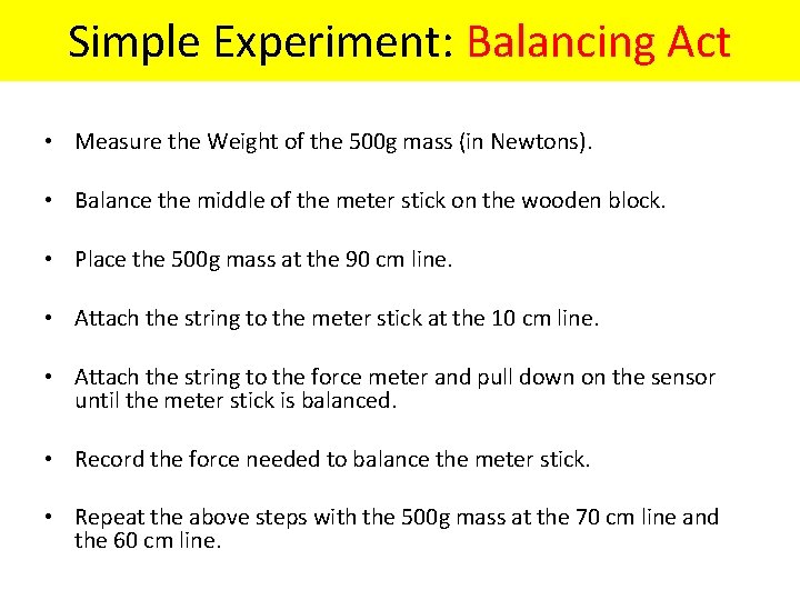
Exploration Lever Forces Simple Experiment: Balancing Act • Measure the Weight of the 500 g mass (in Newtons). • Balance the middle of the meter stick on the wooden block. • Place the 500 g mass at the 90 cm line. • Attach the string to the meter stick at the 10 cm line. • Attach the string to the force meter and pull down on the sensor until the meter stick is balanced. • Record the force needed to balance the meter stick. • Repeat the above steps with the 500 g mass at the 70 cm line and the 60 cm line.
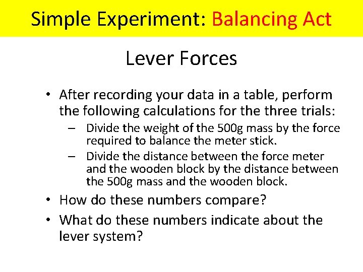
Exploration Simple Experiment: Balancing Act Lever Forces • After recording your data in a table, perform the following calculations for the three trials: – Divide the weight of the 500 g mass by the force required to balance the meter stick. – Divide the distance between the force meter and the wooden block by the distance between the 500 g mass and the wooden block. • How do these numbers compare? • What do these numbers indicate about the lever system?
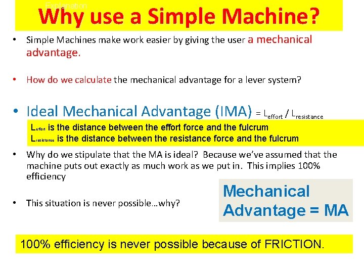
Why use a Simple Machine? Explanation • Simple Machines make work easier by giving the user a mechanical advantage. • How do we calculate the mechanical advantage for a lever system? • Ideal Mechanical Advantage (IMA) = Leffort / Lresistance Leffort is the distance between the effort force and the fulcrum Lresistance is the distance between the resistance force and the fulcrum • Why do we stipulate that the MA is ideal? Because we’ve assumed that the machine puts out exactly as much work as we put in. This implies 100% efficiency • This situation is never possible…why? Mechanical Advantage = MA 100% efficiency is never possible because of FRICTION.
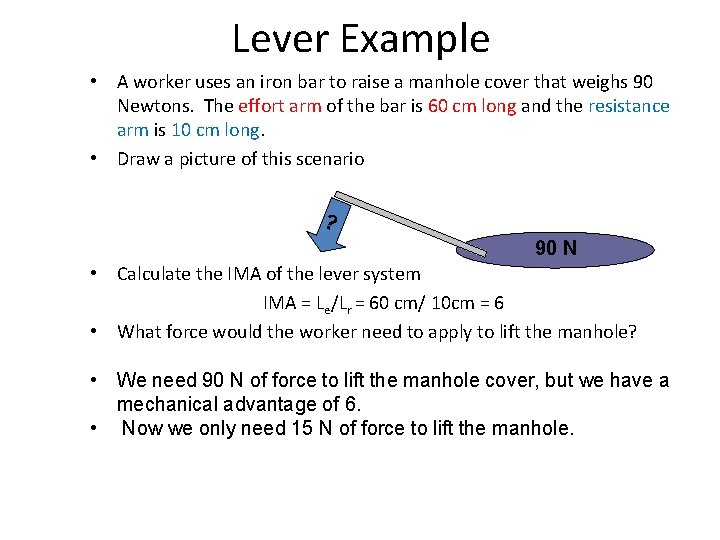
Explanation Lever Example • A worker uses an iron bar to raise a manhole cover that weighs 90 Newtons. The effort arm of the bar is 60 cm long and the resistance arm is 10 cm long. • Draw a picture of this scenario ? 90 N • Calculate the IMA of the lever system IMA = Le/Lr = 60 cm/ 10 cm = 6 • What force would the worker need to apply to lift the manhole? • We need 90 N of force to lift the manhole cover, but we have a mechanical advantage of 6. • Now we only need 15 N of force to lift the manhole.
Three Classes of Levers
First Lever Class
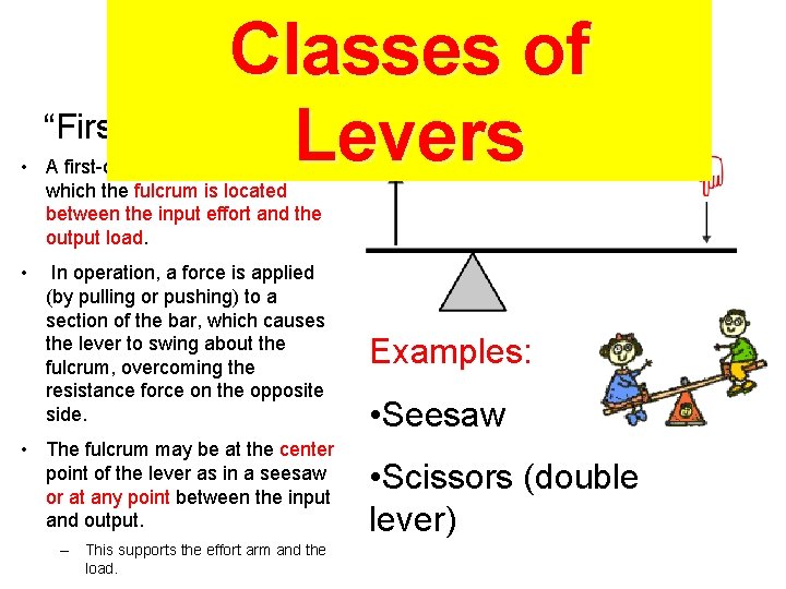
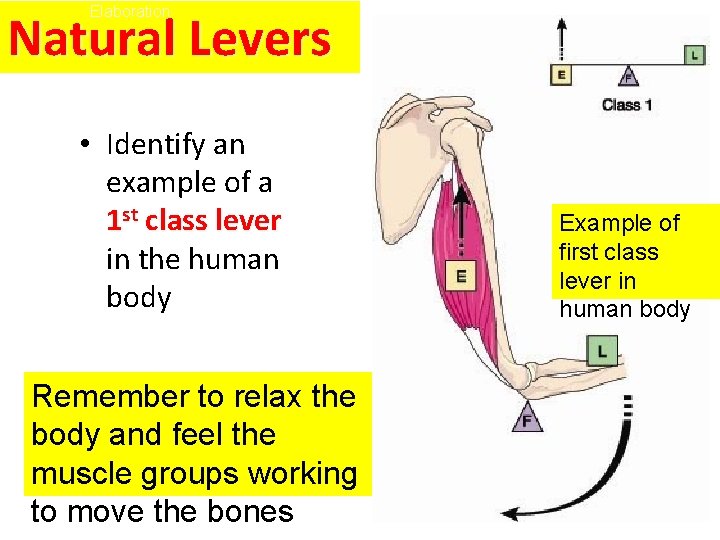
Classes of “First Class Lever” Levers • A first-class lever is a lever in which the fulcrum is located between the input effort and the output load. • In operation, a force is applied (by pulling or pushing) to a section of the bar, which causes the lever to swing about the fulcrum, overcoming the resistance force on the opposite side. • The fulcrum may be at the center point of the lever as in a seesaw or at any point between the input and output. – This supports the effort arm and the load. Examples: • Seesaw • Scissors (double lever)
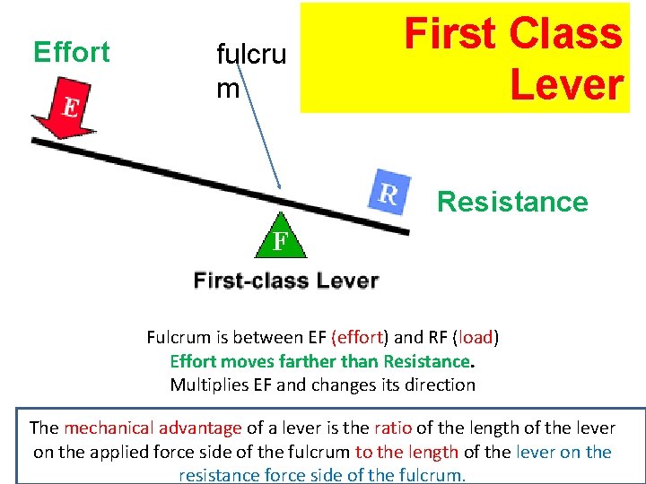
Effort fulcru m First Class Lever Resistance Fulcrum is between EF (effort) and RF (load) Effort moves farther than Resistance. Multiplies EF and changes its direction The mechanical advantage of a lever is the ratio of the length of the lever on the applied force side of the fulcrum to the length of the lever on the resistance force side of the fulcrum.
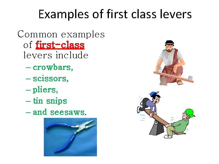
Examples of first class levers Common examples of first-class levers include – crowbars, – scissors, – pliers, – tin snips – and seesaws.
Second Lever Class
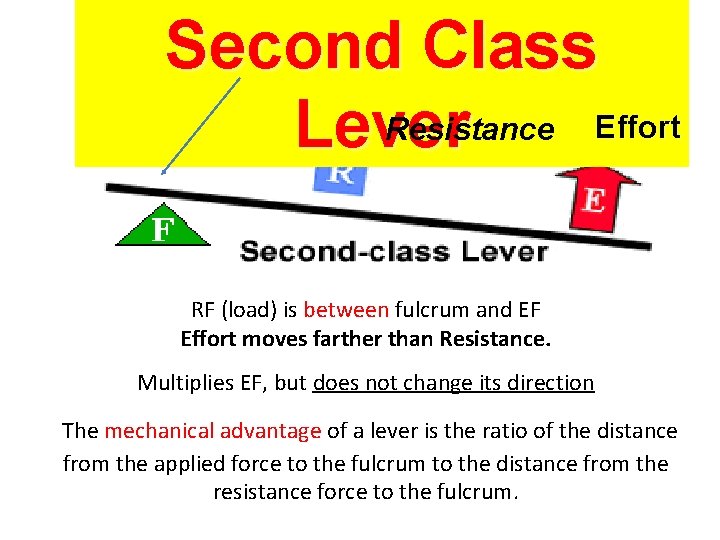
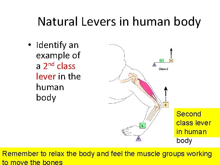
Second Class Resistance Effort Lever RF (load) is between fulcrum and EF Effort moves farther than Resistance. Multiplies EF, but does not change its direction The mechanical advantage of a lever is the ratio of the distance from the applied force to the fulcrum to the distance from the resistance force to the fulcrum.
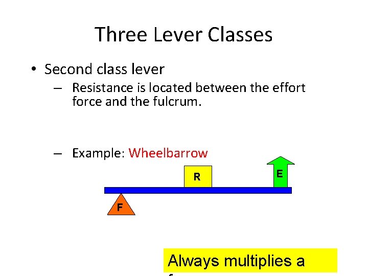
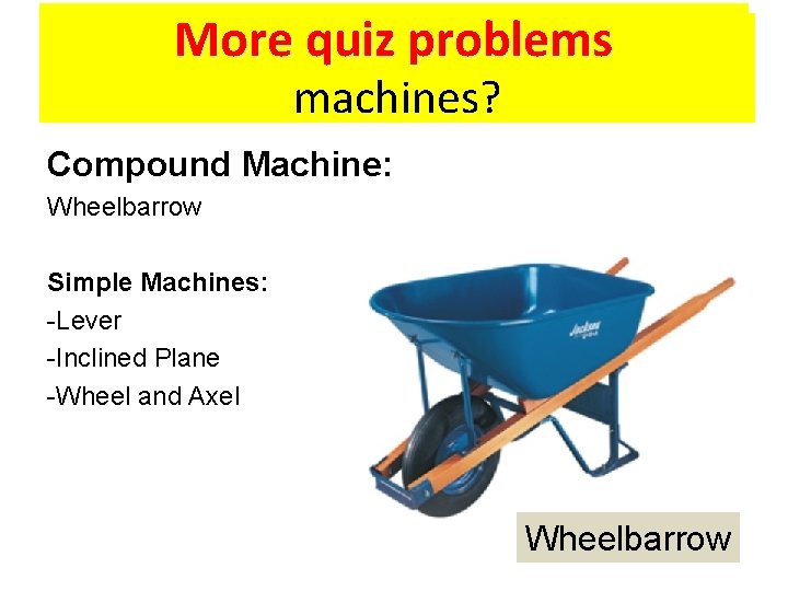
Explanation Three Lever Classes • Second class lever – Resistance is located between the effort force and the fulcrum. – Example: Wheelbarrow R E F Always multiplies a
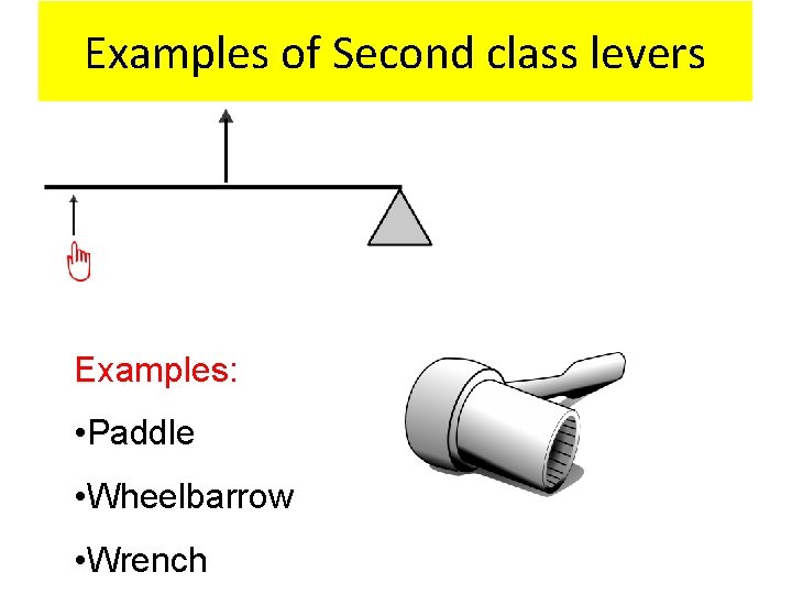
Examples of Second class levers Examples: • Paddle • Wheelbarrow • Wrench
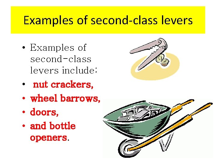
Examples of second-class levers • Examples of second-class levers include: • nut crackers, • wheel barrows, • doors, • and bottle openers
Third Lever Class
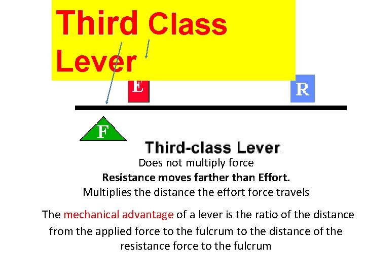
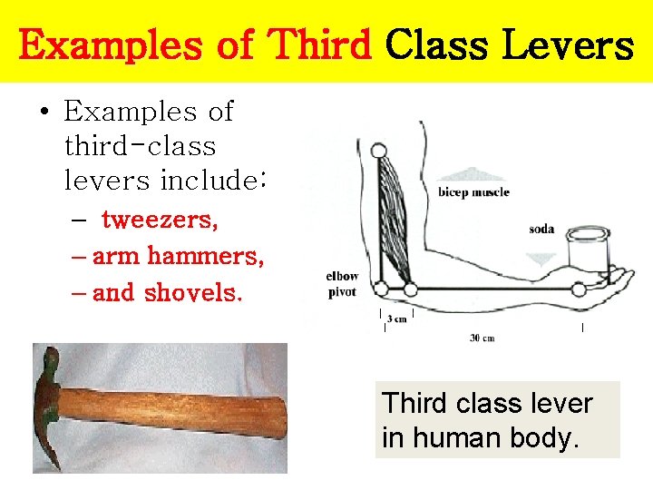
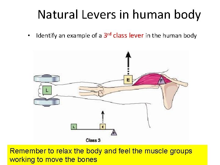
Third Class Lever EF is between fulcrum and RF (load) Does not multiply force Resistance moves farther than Effort. Multiplies the distance the effort force travels The mechanical advantage of a lever is the ratio of the distance from the applied force to the fulcrum to the distance of the resistance force to the fulcrum
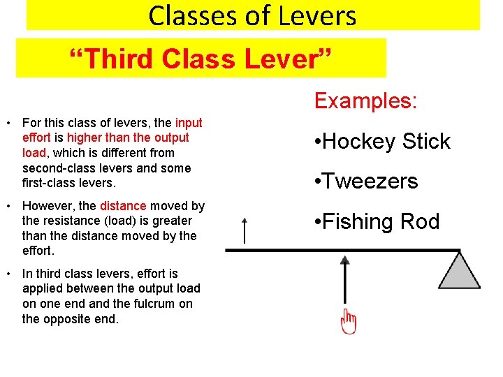
Classes of Levers “Third Class Lever” Examples: • For this class of levers, the input effort is higher than the output load, which is different from second-class levers and some first-class levers. • However, the distance moved by the resistance (load) is greater than the distance moved by the effort. • In third class levers, effort is applied between the output load on one end and the fulcrum on the opposite end. • Hockey Stick • Tweezers • Fishing Rod
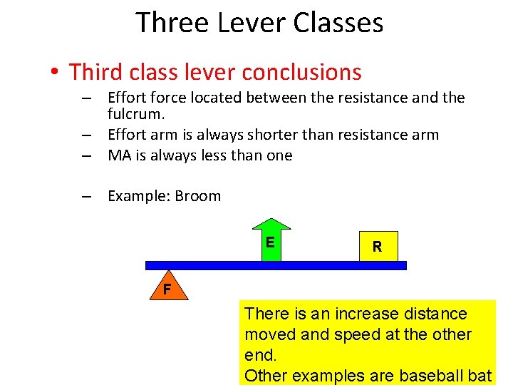
Explanation Three Lever Classes • Third class lever conclusions – Effort force located between the resistance and the fulcrum. – Effort arm is always shorter than resistance arm – MA is always less than one – Example: Broom E R F There is an increase distance moved and speed at the other end. Other examples are baseball bat
Examples of Third Class Levers • Examples of third-class levers include: – tweezers, – arm hammers, – and shovels. Third class lever in human body.
Natural Levers in Human Body
Elaboration Natural Levers • Identify an example of a 1 st class lever in the human body Remember to relax the body and feel the muscle groups working to move the bones Example of first class lever in human body
Elaboration Natural Levers in human body • Identify an example of a 2 nd class lever in the human body Second class lever in human body Remember to relax the body and feel the muscle groups working to move the bones
Natural Levers in human body • Identify an example of a 3 rd class lever in the human body Remember to relax the body and feel the muscle groups working to move the bones
Mechanical Advantage and Velocity Ratio
Mechanical Advantage • Mechanical Advantage is the ratio between the load and effort. • Mechanical Advantage deals only with forces. • Mechanical Advantage > 1 means that the output force will be greater than the input force. – (But the input distance will need to be greater than the output distance. )
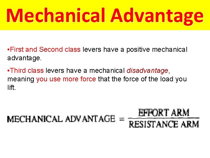
Mechanical Advantage • First and Second class levers have a positive mechanical advantage. • Third class levers have a mechanical disadvantage, meaning you use more force that the force of the load you lift.
Velocity Ratio • Velocity Ratio deals with the distance gained or lost due to a mechanical advantage. • Velocity Ratio >1 means that the input distance (or effort) to move a load will be greater than the output distance of the load.
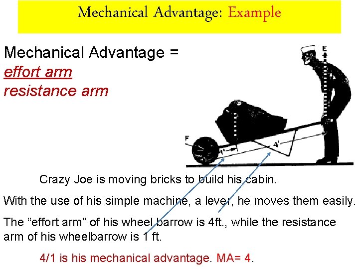
Mechanical Advantage: Example Mechanical Advantage = effort arm resistance arm Crazy Joe is moving bricks to build his cabin. With the use of his simple machine, a lever, he moves them easily. The “effort arm” of his wheel barrow is 4 ft. , while the resistance arm of his wheelbarrow is 1 ft. 4/1 is his mechanical advantage. MA= 4.
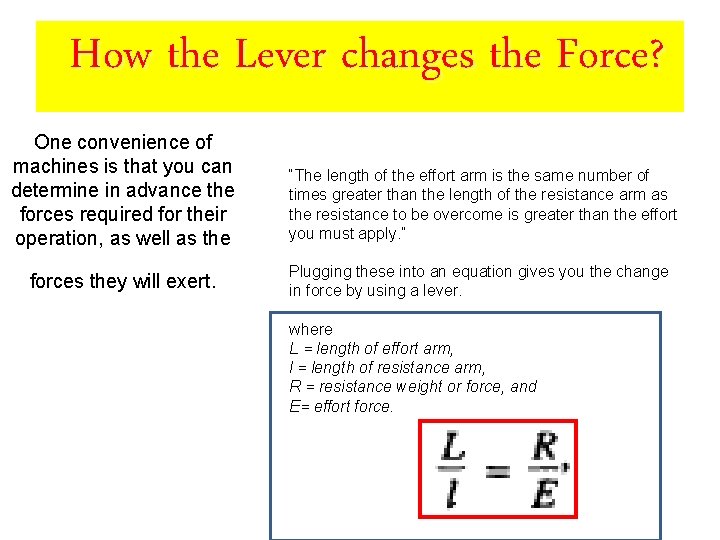
How the Lever changes the Force? One convenience of machines is that you can determine in advance the forces required for their operation, as well as the “The length of the effort arm is the same number of times greater than the length of the resistance arm as the resistance to be overcome is greater than the effort you must apply. ” forces they will exert. Plugging these into an equation gives you the change in force by using a lever. where L = length of effort arm, l = length of resistance arm, R = resistance weight or force, and E= effort force.
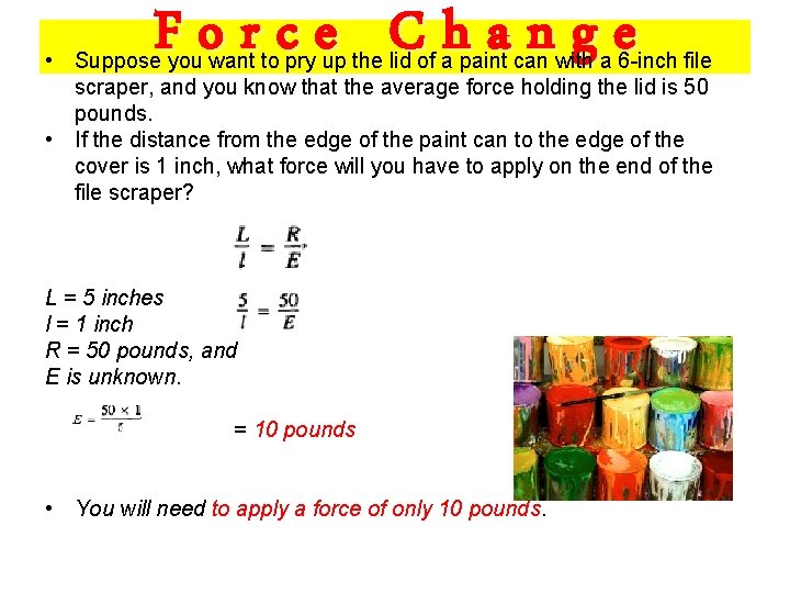
Force Change • Suppose you want to pry up the lid of a paint can with a 6 -inch file scraper, and you know that the average force holding the lid is 50 pounds. • If the distance from the edge of the paint can to the edge of the cover is 1 inch, what force will you have to apply on the end of the file scraper? L = 5 inches l = 1 inch R = 50 pounds, and E is unknown. = 10 pounds • You will need to apply a force of only 10 pounds.
Rotary Mechanisms
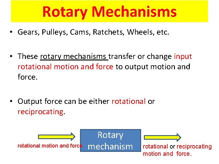
Rotary Mechanisms • Gears, Pulleys, Cams, Ratchets, Wheels, etc. • These rotary mechanisms transfer or change input rotational motion and force to output motion and force. • Output force can be either rotational or reciprocating. rotational motion and force Rotary mechanism rotational or reciprocating motion and force.
Belts/Pulleys & Chains/Sprockets • Use belts and chains to convert motion and force. • Uses the same measures of Mechanical advantage and Velocity Ratio also for belts, pulleys, chains, sprockets and gears.
Inclined Plane
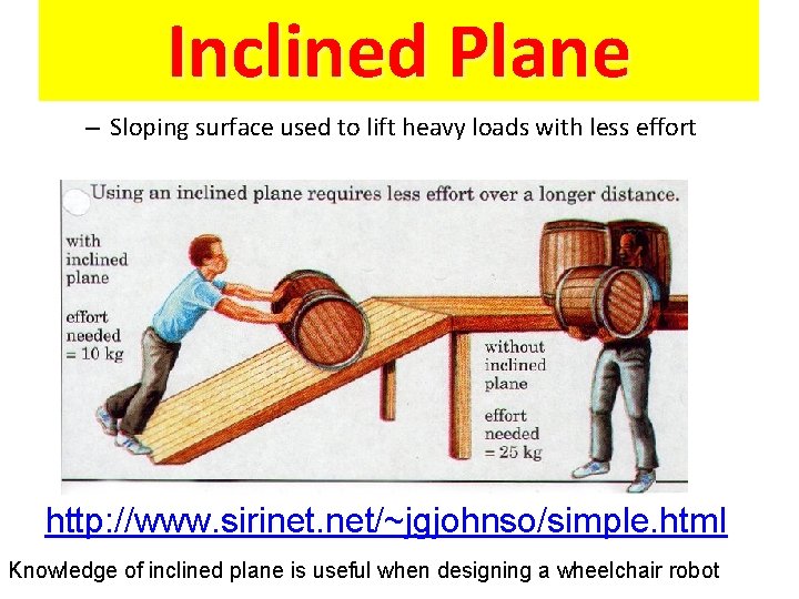
Inclined Plane – Sloping surface used to lift heavy loads with less effort http: //www. sirinet. net/~jgjohnso/simple. html Knowledge of inclined plane is useful when designing a wheelchair robot
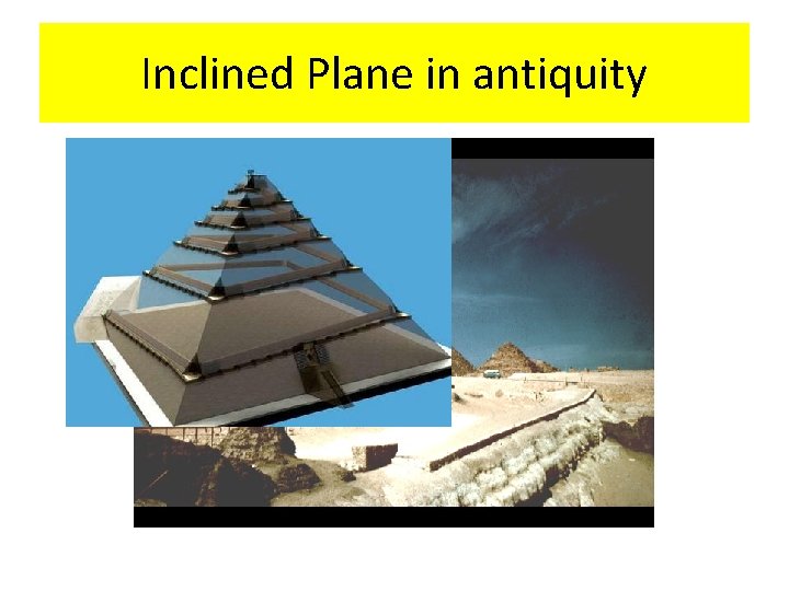
Inclined Plane in antiquity
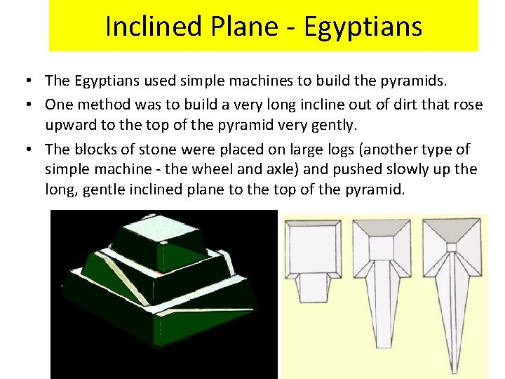
Inclined Plane - Egyptians • The Egyptians used simple machines to build the pyramids. • One method was to build a very long incline out of dirt that rose upward to the top of the pyramid very gently. • The blocks of stone were placed on large logs (another type of simple machine - the wheel and axle) and pushed slowly up the long, gentle inclined plane to the top of the pyramid.
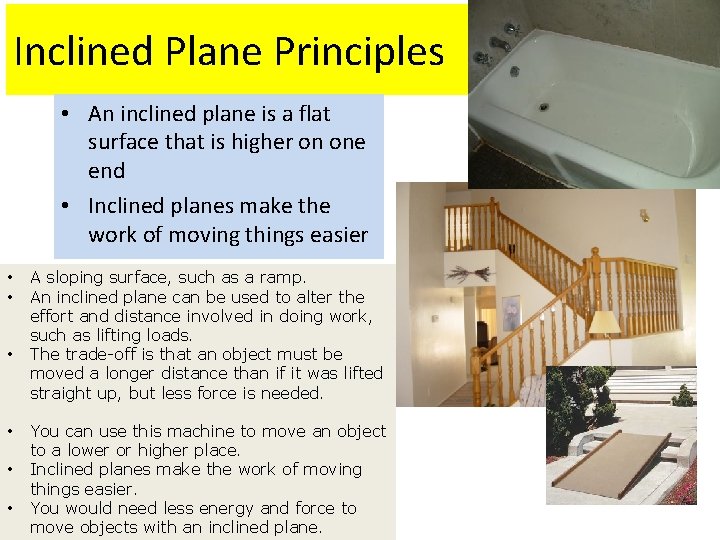
Inclined Plane Principles • An inclined plane is a flat surface that is higher on one end • Inclined planes make the work of moving things easier • • • A sloping surface, such as a ramp. An inclined plane can be used to alter the effort and distance involved in doing work, such as lifting loads. The trade-off is that an object must be moved a longer distance than if it was lifted straight up, but less force is needed. You can use this machine to move an object to a lower or higher place. Inclined planes make the work of moving things easier. You would need less energy and force to move objects with an inclined plane.
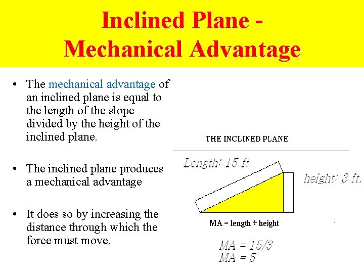
Inclined Plane Mechanical Advantage • The mechanical advantage of an inclined plane is equal to the length of the slope divided by the height of the inclined plane. • The inclined plane produces a mechanical advantage • It does so by increasing the distance through which the force must move.
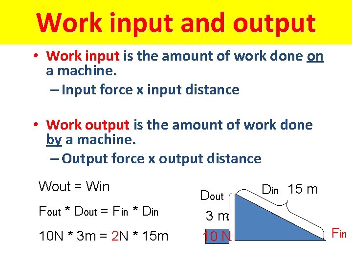
Work input and output • Work input is the amount of work done on a machine. – Input force x input distance • Work output is the amount of work done by a machine. – Output force x output distance Wout = Win Fout * Dout = Fin * Din Dout 3 m 10 N * 3 m = 2 N * 15 m 10 N Din 15 m Fin
Screw
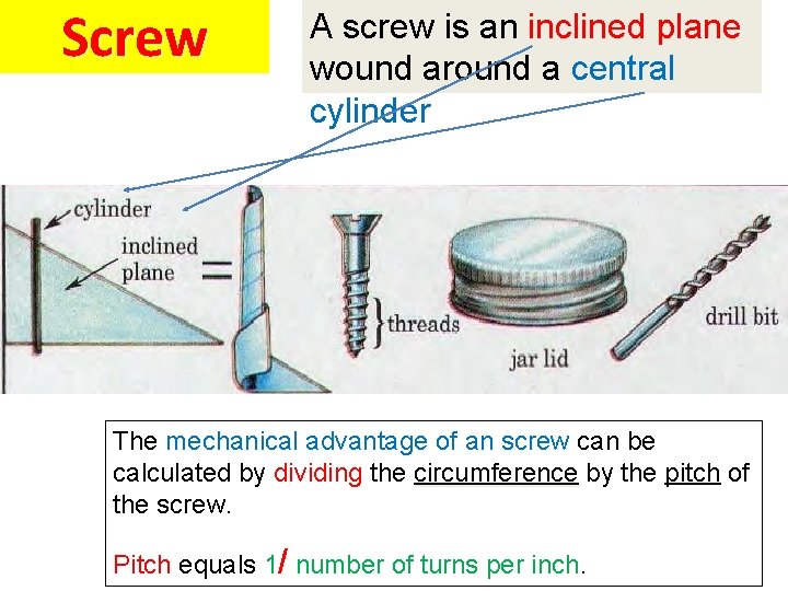
Screw A screw is an inclined plane wound around a central cylinder The mechanical advantage of an screw can be calculated by dividing the circumference by the pitch of the screw. Pitch equals 1/ number of turns per inch.
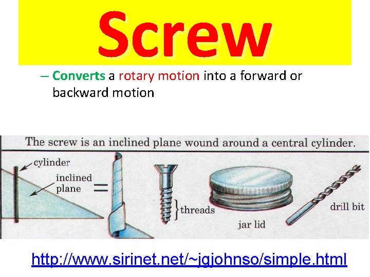
Screw – Converts a rotary motion into a forward or backward motion http: //www. sirinet. net/~jgjohnso/simple. html
Wedges
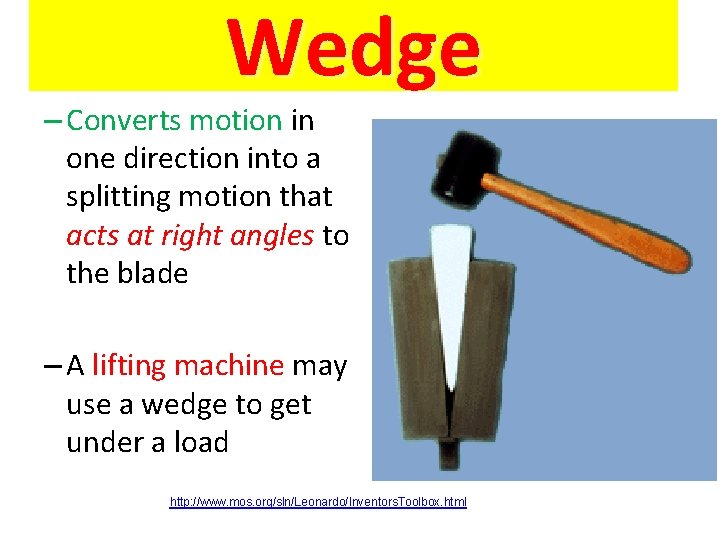
Wedge – Converts motion in one direction into a splitting motion that acts at right angles to the blade – A lifting machine may use a wedge to get under a load http: //www. mos. org/sln/Leonardo/Inventors. Toolbox. html
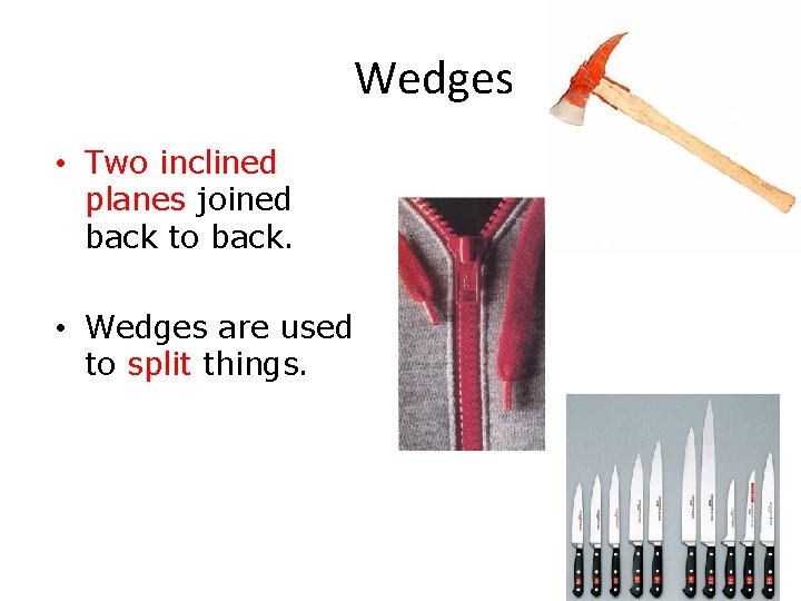
Wedges • Two inclined planes joined back to back. • Wedges are used to split things.
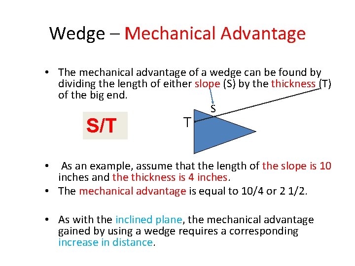
Wedge – Mechanical Advantage • The mechanical advantage of a wedge can be found by dividing the length of either slope (S) by the thickness (T) of the big end. S S/T T • As an example, assume that the length of the slope is 10 inches and the thickness is 4 inches. • The mechanical advantage is equal to 10/4 or 2 1/2. • As with the inclined plane, the mechanical advantage gained by using a wedge requires a corresponding increase in distance.
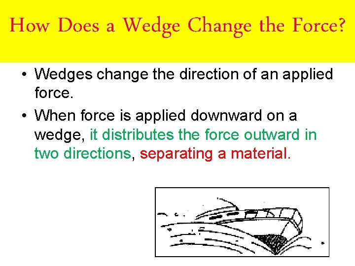
How Does a Wedge Change the Force? • Wedges change the direction of an applied force. • When force is applied downward on a wedge, it distributes the force outward in two directions, separating a material.
… more examples of … Compound Machines
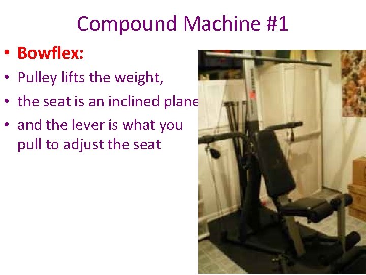
Compound Machine #1 • Bowflex: • Pulley lifts the weight, • the seat is an inclined plane, • and the lever is what you pull to adjust the seat
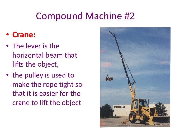
Compound Machine #2 • Crane: • The lever is the horizontal beam that lifts the object, • the pulley is used to make the rope tight so that it is easier for the crane to lift the object
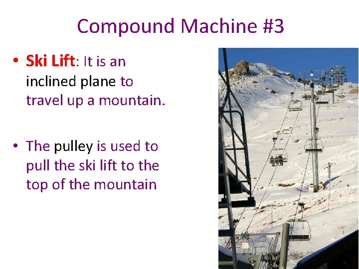
Compound Machine #3 • Ski Lift: It is an inclined plane to travel up a mountain. • The pulley is used to pull the ski lift to the top of the mountain
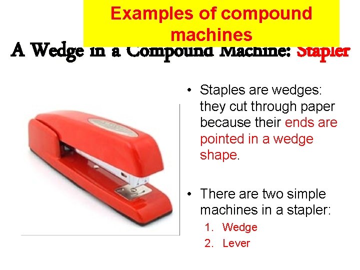
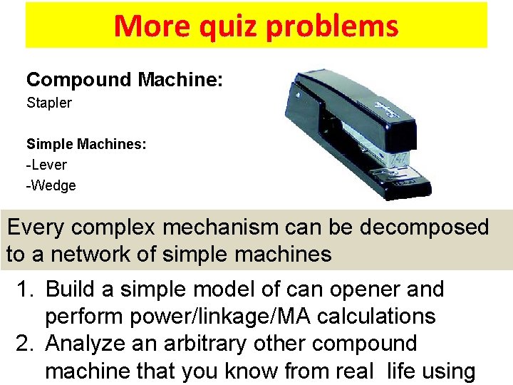
Examples of compound machines A Wedge in a Compound Machine: Stapler • Staples are wedges: they cut through paper because their ends are pointed in a wedge shape. • There are two simple machines in a stapler: 1. Wedge 2. Lever
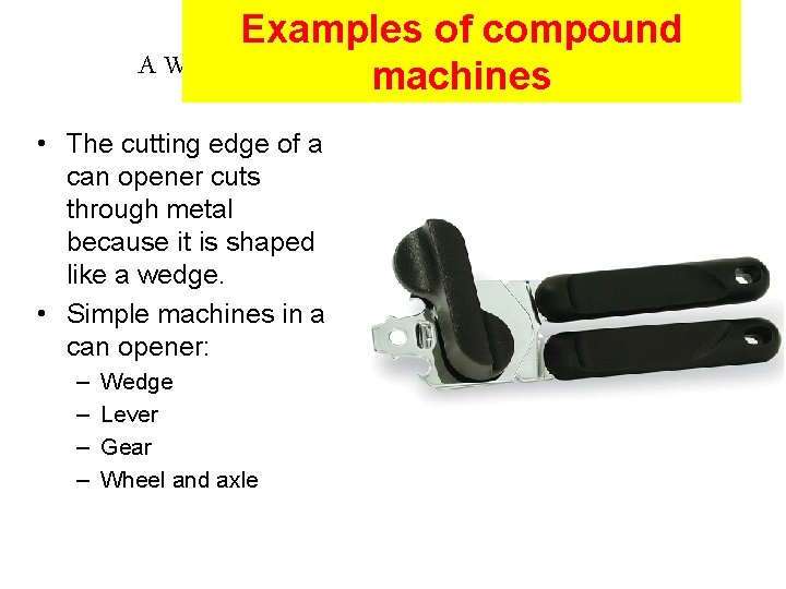
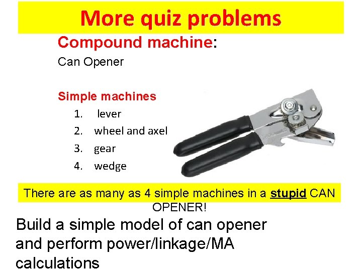
Examples of compound A Wedge in a Compound Machine: Can Opener machines • The cutting edge of a can opener cuts through metal because it is shaped like a wedge. • Simple machines in a can opener: – – Wedge Lever Gear Wheel and axle
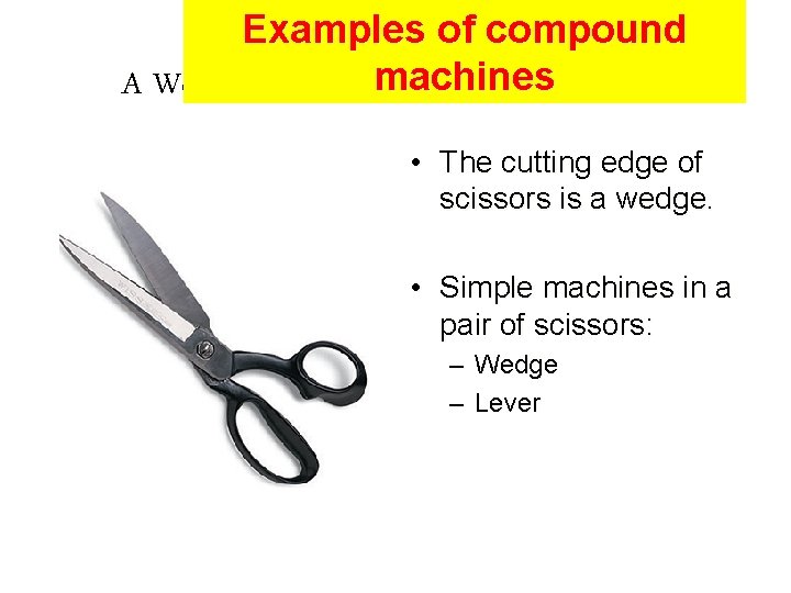
Examples of compound machines A Wedge in a Compound Machine: Scissors • The cutting edge of scissors is a wedge. • Simple machines in a pair of scissors: – Wedge – Lever
Project Related 1. Create a kinematic model of your robot 2. Relate it to pulleys, gears, levers, linkages, etc 3. Perform simple calculations related to torque, speed and power
Levers and Linkages: Conclusions Concepts discussed Understanding of levers and linkages is important for those who build robots, especially humanoids • • Fulcrum Load Effort Classes – First – Second – Third It is useful to look to Nature for examples of mechanical designs (Leonardo Da Vinci)
Philosophy • Be able to see and appreciate simple machines around you • Be able to steal every mechanical idea from any kind of machines for the robot that you are building.
Questions and Problems
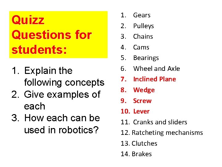
Quizz Questions for students: 1. Explain the following concepts 2. Give examples of each 3. How each can be used in robotics? 1. Gears 2. Pulleys 3. Chains 4. Cams 5. Bearings 6. Wheel and Axle 7. Inclined Plane 8. Wedge 9. Screw 10. Lever 11. Cranks and sliders 12. Ratcheting mechanisms 13. Clutches 14. Brakes
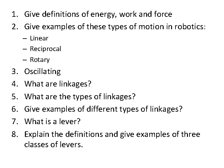
1. Give definitions of energy, work and force 2. Give examples of these types of motion in robotics: – Linear – Reciprocal – Rotary 3. 4. 5. 6. 7. 8. Oscillating What are linkages? What are the types of linkages? Give examples of different types of linkages? What is a lever? Explain the definitions and give examples of three classes of levers.
1. Give definition of mechanical advantage 2. Give examples of mechanical advantages in simple machines such as various classes of levers. 3. Give at least three examples of compound machines. 4. What are Parallel Linkages, Treadle Linkages amd Toggle Linkages 5. What is a rotary mechanism? 6. Describe a humanoid arm as a compund machine. 7. The same for a leg 8. The same for a torso 9. The same for a head and neck combination.
Simple problems for quizz 1. How much effort will be needed to lift a 100 pound load if distance to effort is five feet and distance to resistance is one foot? 2. How much effort will be needed to lift a 48 pound load if distance to effort is two feet and distance to resistance is 8 feet?
More quiz problems Compound machine: Can Opener Simple machines 1. lever 2. wheel and axel 3. gear 4. wedge There as many as 4 simple machines in a stupid CAN OPENER! Build a simple model of can opener and perform power/linkage/MA calculations
More quiz problems Compound Machine: Stapler Simple Machines: -Lever -Wedge Every complex mechanism can be decomposed to a network of simple machines 1. Build a simple model of can opener and perform power/linkage/MA calculations 2. Analyze an arbitrary other compound machine that you know from real life using
Where I find compound Morecan quiz problems machines? Compound Machine: Wheelbarrow Simple Machines: -Lever -Inclined Plane -Wheel and Axel Wheelbarrow
Questions and Problems 1. What is kinematics? Why is kinematics important for robot design and programming? 2. Draw a kinematic model of Jimmy robot. 3. Draw a kinematic model of new robot Meccanoid 4. Draw a kinematic model of In. Moo. V robot. 5. Give example of First Lever Class in a robot, especially a humanoid robot. 6. Give example of Second Lever Class in a robot, especially a humanoid robot. 7. Give example of Third Lever Class in a robot, especially a humanoid robot. 8. How the Lever changes the Force? 9. Propose your own design of a robotic arm with four degrees of freedom, using as many as possible concepts from this set of slides. Optimize the robot arm envelope, and assume low cost motors. Add gears, pulleys, levers. 10. Perform calculations for robot arms that were requested in last few sets of slides. Now you can do them as you learned theory!
Bibliography • http: //en. wikipedia. org/wiki/Lever I got the three types of levers, examples and their functions. (used) • http: //www. tpub. com/machines/1 c. htm I got the formula for mechanical advantage and example. (used) • http: //www. edheads. org/activities/simple-machines/frame_loader. htm I found a list of compound machines and how simple machines were used in them. (used) • http: //www. coe. uh. edu/archive/science_lessons/scienceles 1/lever. h tm I found examples of levers and how they work.
Bibliography • http: //dictionary. reference. com/browse/wedge • http: //www. uark. edu/depts/aeedhp/agscience/s impmach. htm • http: //www. sciencetechnomuses. ca/englis h/schoolzone/Info_Simple_Machines 2. cfm • http: //www. edheads. org/activities/simplemachines/frame_loader. htm • http: //www. teachervision. fen. com/machines/print able/45019. html
Bibliography • http: //library. thinkquest. org/27948/pulley. html – This site explains the use of the pulley system. Also provides an equation to figure out the force needed to lift an object with the pulley. • *http: //library. thinkquest. org/J 002079 F/pulley. htm – This site defines a pulley and explains how it makes lifting easier. This site also shows simple examples of pulleys. • http: //www. science. jrank. org/pages/4060/Machines-Simple. html I used this site to find mechanical advantages, examples, and how a basic lever works.
Bibliography (Cont. ) *http: //en. wikipedia. org/wiki/Pulley – This site gave the definition of a pulley, different types of pulley systems, and explains how these systems work. • http: //www. swe. org/iac/lp/pulley_03. html – This site gives a detailed explanation about pulleys. It shows how it was invented, by whom it was invented, and provides pictures to show a pulley works. • *http: //library. thinkquest. org/CR 0210120/MA%20 of %20 PS. html – This site showed how to get the mechanical advantage for a pulley.
Sources Shawni Yeagley Nate Yavoich Raquel y Victoria