THEORY CONCEPTS References LWR MANUAL1996 Includes CS up



- Slides: 68
THEORY & CONCEPTS
References • LWR MANUAL-1996 • Includes CS up to no. 8 • Last CS issued – 16 of 2014
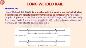
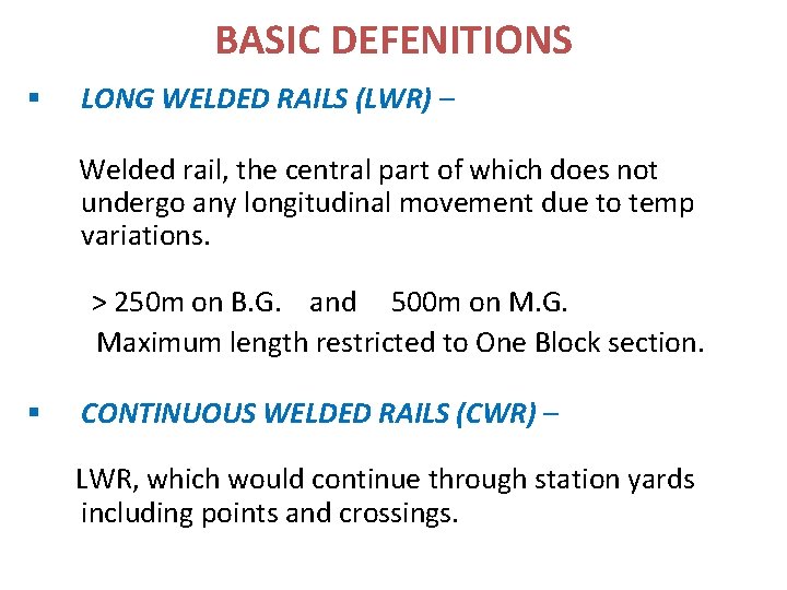
BASIC DEFENITIONS § LONG WELDED RAILS (LWR) – Welded rail, the central part of which does not undergo any longitudinal movement due to temp variations. > 250 m on B. G. and 500 m on M. G. Maximum length restricted to One Block section. § CONTINUOUS WELDED RAILS (CWR) – LWR, which would continue through station yards including points and crossings.
BASIC DEFENITIONS (Contd. ) § BREATHING LENGTH Length at each end of LWR/CWR which is subjected to expansion/ contraction on account of temp. variations. Varies with Temp zone & Type of track structure (Annexure I-A, I-B & I-C for sleeper density 1310, 1540 & 1660) BREATHING LENGTHS SEJ Non Breathing length TOTAL LENGTH OF LWR SEJ
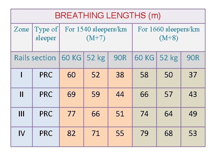
BREATHING LENGTHS (m) Zone Type of sleeper For 1540 sleepers/km (M+7) Rails section 60 KG 52 kg For 1660 sleepers/km (M+8) 90 R 60 KG 52 kg 90 R I PRC 60 52 38 58 50 37 II PRC 69 59 44 66 57 43 III PRC 77 66 51 74 64 49 IV PRC 82 71 55 79 68 53
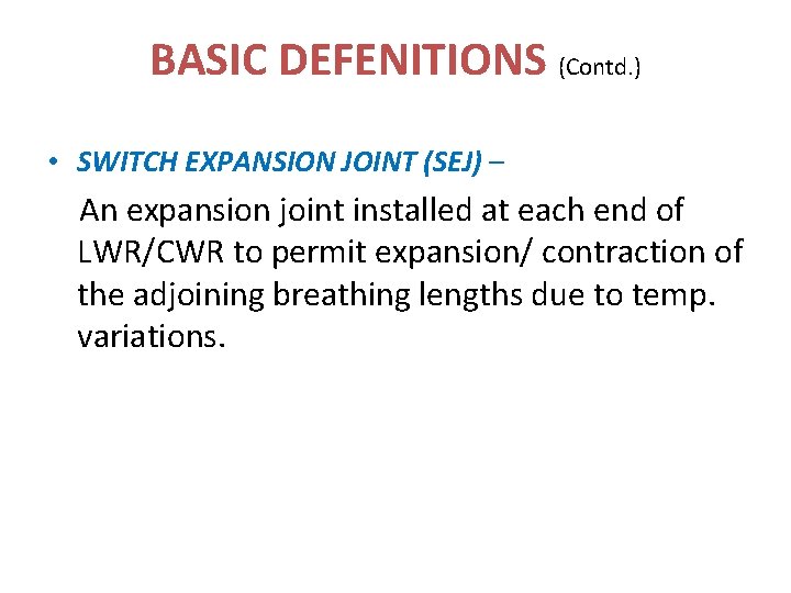
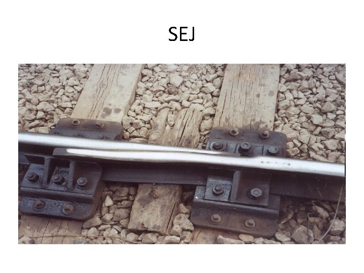
BASIC DEFENITIONS (Contd. ) • SWITCH EXPANSION JOINT (SEJ) – An expansion joint installed at each end of LWR/CWR to permit expansion/ contraction of the adjoining breathing lengths due to temp. variations.
SEJ
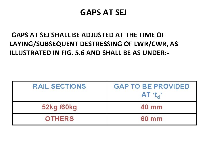
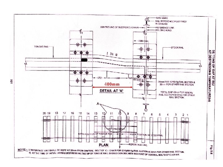
GAPS AT SEJ SHALL BE ADJUSTED AT THE TIME OF LAYING/SUBSEQUENT DESTRESSING OF LWR/CWR, AS ILLUSTRATED IN FIG. 5. 6 AND SHALL BE AS UNDER: - RAIL SECTIONS GAP TO BE PROVIDED AT ‘td’ 52 kg /60 kg 40 mm OTHERS 60 mm
400 mm
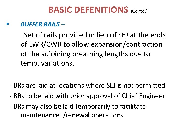
BASIC DEFENITIONS (Contd. ) § BUFFER RAILS – Set of rails provided in lieu of SEJ at the ends of LWR/CWR to allow expansion/contraction of the adjoining breathing lengths due to temp. variations. - BRs are laid at locations where SEJ is not permitted - BRs to be laid with prior approval of Chief Engineer - BRs may also be laid temporarily to facilitate maintenance /renewal operations
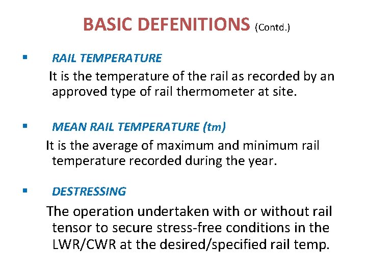
BASIC DEFENITIONS (Contd. ) § RAIL TEMPERATURE It is the temperature of the rail as recorded by an approved type of rail thermometer at site. § MEAN RAIL TEMPERATURE (tm) It is the average of maximum and minimum rail temperature recorded during the year. § DESTRESSING The operation undertaken with or without rail tensor to secure stress-free conditions in the LWR/CWR at the desired/specified rail temp.
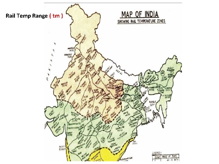
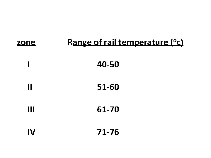
Rail Temp Range ( tm )
zone Range of rail temperature (oc) I 40 -50 II 51 -60 III 61 -70 IV 71 -76
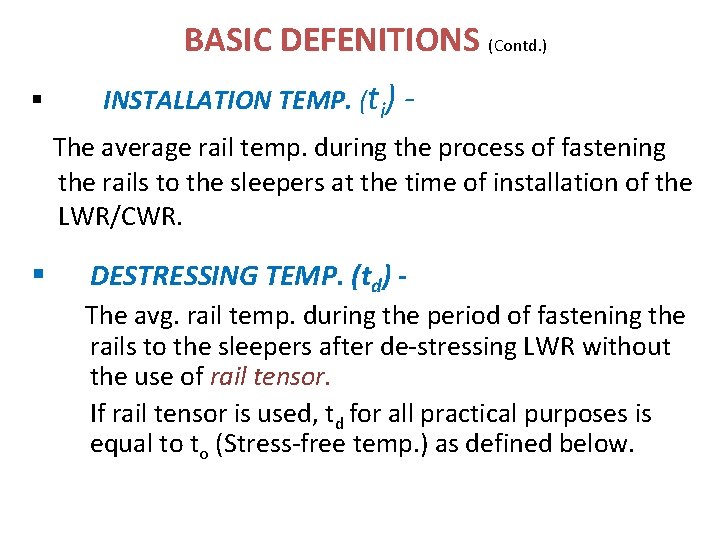
BASIC DEFENITIONS (Contd. ) § INSTALLATION TEMP. (ti) The average rail temp. during the process of fastening the rails to the sleepers at the time of installation of the LWR/CWR. § DESTRESSING TEMP. (td) The avg. rail temp. during the period of fastening the rails to the sleepers after de-stressing LWR without the use of rail tensor. If rail tensor is used, td for all practical purposes is equal to to (Stress-free temp. ) as defined below.
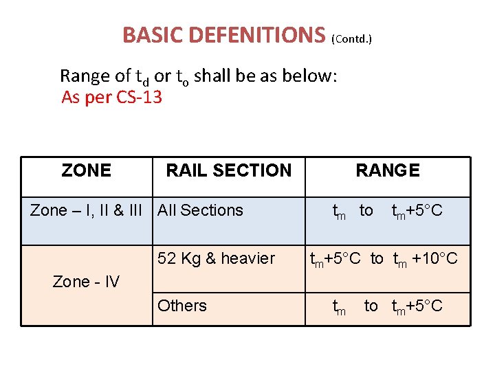
BASIC DEFENITIONS (Contd. ) Range of td or to shall be as below: As per CS-13 ZONE RAIL SECTION Zone – I, II & III All Sections 52 Kg & heavier RANGE tm to tm+5°C to tm +10°C Zone - IV Others tm to tm+5°C
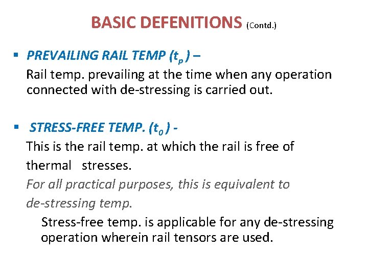
BASIC DEFENITIONS (Contd. ) § PREVAILING RAIL TEMP (tp ) – Rail temp. prevailing at the time when any operation connected with de-stressing is carried out. § STRESS-FREE TEMP. (t 0 ) This is the rail temp. at which the rail is free of thermal stresses. For all practical purposes, this is equivalent to de-stressing temp. Stress-free temp. is applicable for any de-stressing operation wherein rail tensors are used.
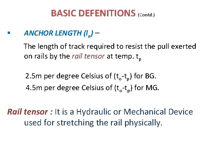
BASIC DEFENITIONS (Contd. ) § ANCHOR LENGTH (la) – The length of track required to resist the pull exerted on rails by the rail tensor at temp. tp 2. 5 m per degree Celsius of (to-tp) for BG. 4. 5 m per degree Celsius of (to-tp) for MG. Rail tensor : It is a Hydraulic or Mechanical Device used for stretching the rail physically.
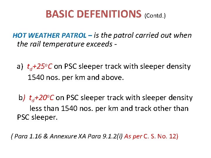
BASIC DEFENITIONS (Contd. ) HOT WEATHER PATROL – is the patrol carried out when the rail temperature exceeds - a) td+25 o. C on PSC sleeper track with sleeper density 1540 nos. per km and above. b) td+20 o. C on PSC sleeper track with sleeper density less than 1540 nos. per km and track other than PSC sleeper. ( Para 1. 16 & Annexure XA Para 9. 1. 2(i) As per C. S. No. 12)
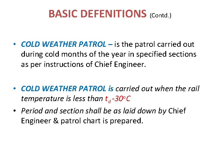
BASIC DEFENITIONS (Contd. ) • COLD WEATHER PATROL – is the patrol carried out during cold months of the year in specified sections as per instructions of Chief Engineer. • COLD WEATHER PATROL is carried out when the rail temperature is less than td -30 o. C • Period and section shall be as laid down by Chief Engineer & patrol chart is prepared.
BASIC DEFENITIONS (Contd. ) CONSOLIDATION OF TRACK- process of building up ballast resistance – FOR OTHER THAN CONCRETE SLEEPERS Min passage of traffic shall be • WHEN BALLAST COMPACTION DONE WITH HAND OPERATED COMPACTORS – BG 3, 000 GROSS TONNES OF TRAFFIC – MG 1, 000 GROSS TONNES OF TRAFFIC • MECHANISED SHOULDER AND CRIB COMPACTOR – BG 50, 000 GROSS TONNES OF TRAFFIC – MG 20, 000 GROSS TONNES OF TRAFFIC OR MINIMUM OF TWO DAYS WHICHEVWR IS LATER
BASIC DEFENITIONS (Contd. ) – CONCRETE SLEEPERS Min passage of traffic shall be • BG 50, 000 GROSS TONNES • MG 20, 000 GROSS TONNES OR MINIMUM OF TWO DAYS WHICHEVER IS LATER – ATLEAST ONE ROUND OF STABILISATION BY DTS – FOR NEWLY LAID LWR/CWR, AT LEAST 3 ROUNDS OF PACKING ( LAST TWO WITH ON TRACK TAMPER)
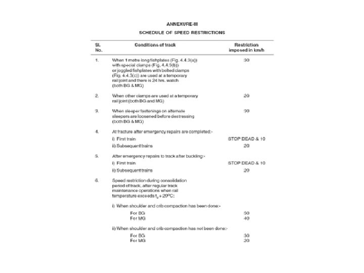
Contd. … Speed Restriction to be imposed if temp. goes beyond td+200 C during consolidation period. (for PSC sleeper track) – • B. G. - 50 kmph • M. G. - 40 kmph (As per C. S. No-9)
PERMITTED LOCATIONS ALIGNMENT: Ø LWR/CWR Shall not be laid on curves sharper than 440 m radius (4 o ) both for BG & MG. As per C. S. No-11 (para 3. 2. 1) - However in temp. Zone – I, LWR/CWR can be laid on curves up to 360 m radius (5 o ) on BG, with following precautions • Min. track structure - 52 kg rail on PSC, (m+7) density, 300 mm ballast cushion • Shoulder ballast for curves sharper than 440 m should be increase to 600 mm on outside of curve and should be provided for 100 m beyond the tangent point • Reference marks at every 50 m to record creep
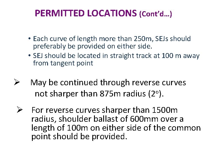
PERMITTED LOCATIONS (Cont’d…) • Each curve of length more than 250 m, SEJs should preferably be provided on either side. • SEJ should be located in straight track at 100 m away from tangent point Ø May be continued through reverse curves not sharper than 875 m radius (2 o). Ø For reverse curves sharper than 1500 m radius, shoulder ballast of 600 mm over a length of 100 m on either side of the common point should be provided.
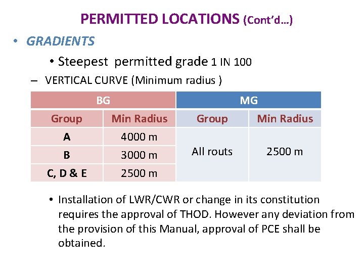
PERMITTED LOCATIONS (Cont’d…) • GRADIENTS • Steepest permitted grade 1 IN 100 – VERTICAL CURVE (Minimum radius ) BG Group A B Min Radius 4000 m 3000 m C, D & E 2500 m MG Group Min Radius All routs 2500 m • Installation of LWR/CWR or change in its constitution requires the approval of THOD. However any deviation from the provision of this Manual, approval of PCE shall be obtained.
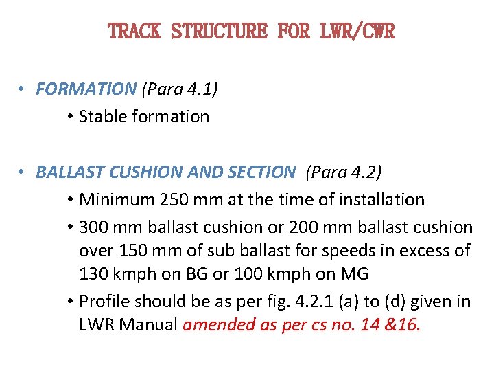
TRACK STRUCTURE FOR LWR/CWR • FORMATION (Para 4. 1) • Stable formation • BALLAST CUSHION AND SECTION (Para 4. 2) • Minimum 250 mm at the time of installation • 300 mm ballast cushion or 200 mm ballast cushion over 150 mm of sub ballast for speeds in excess of 130 kmph on BG or 100 kmph on MG • Profile should be as per fig. 4. 2. 1 (a) to (d) given in LWR Manual amended as per cs no. 14 &16.
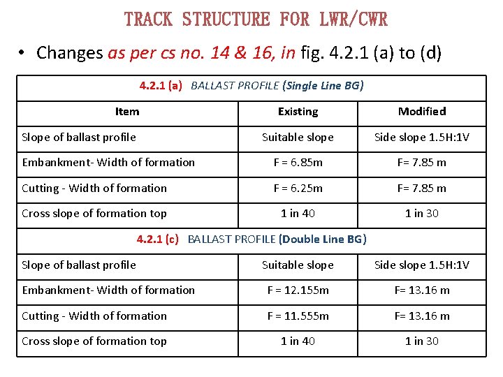
TRACK STRUCTURE FOR LWR/CWR • Changes as per cs no. 14 & 16, in fig. 4. 2. 1 (a) to (d) 4. 2. 1 (a) BALLAST PROFILE (Single Line BG) Item Existing Modified Suitable slope Side slope 1. 5 H: 1 V Embankment- Width of formation F = 6. 85 m F= 7. 85 m Cutting - Width of formation F = 6. 25 m F= 7. 85 m Cross slope of formation top 1 in 40 1 in 30 Slope of ballast profile 4. 2. 1 (c) BALLAST PROFILE (Double Line BG) Slope of ballast profile Suitable slope Side slope 1. 5 H: 1 V Embankment- Width of formation F = 12. 155 m F= 13. 16 m Cutting - Width of formation F = 11. 555 m F= 13. 16 m Cross slope of formation top 1 in 40 1 in 30
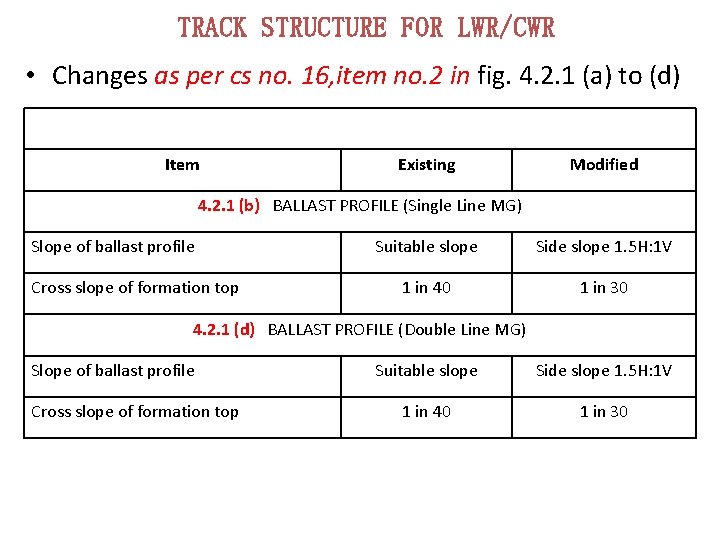
TRACK STRUCTURE FOR LWR/CWR • Changes as per cs no. 16, item no. 2 in fig. 4. 2. 1 (a) to (d) Item Existing Modified 4. 2. 1 (b) BALLAST PROFILE (Single Line MG) Slope of ballast profile Cross slope of formation top Suitable slope Side slope 1. 5 H: 1 V 1 in 40 1 in 30 4. 2. 1 (d) BALLAST PROFILE (Double Line MG) Slope of ballast profile Cross slope of formation top Suitable slope Side slope 1. 5 H: 1 V 1 in 40 1 in 30
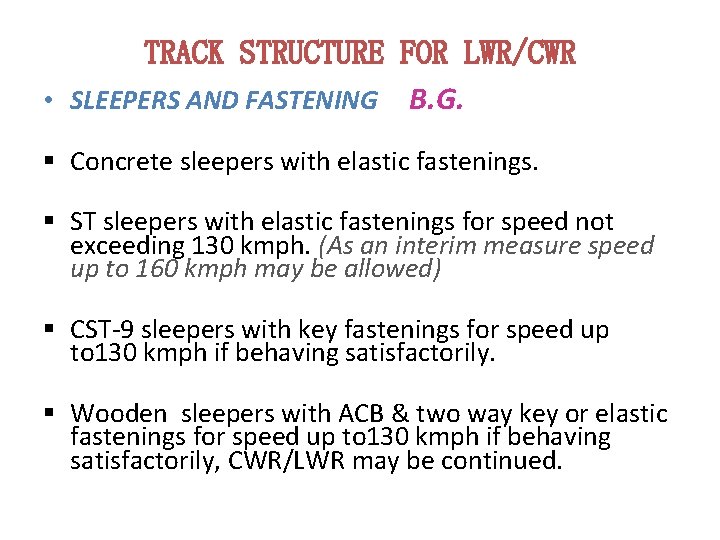
TRACK STRUCTURE FOR LWR/CWR • SLEEPERS AND FASTENING B. G. § Concrete sleepers with elastic fastenings. § ST sleepers with elastic fastenings for speed not exceeding 130 kmph. (As an interim measure speed up to 160 kmph may be allowed) § CST-9 sleepers with key fastenings for speed up to 130 kmph if behaving satisfactorily. § Wooden sleepers with ACB & two way key or elastic fastenings for speed up to 130 kmph if behaving satisfactorily, CWR/LWR may be continued.
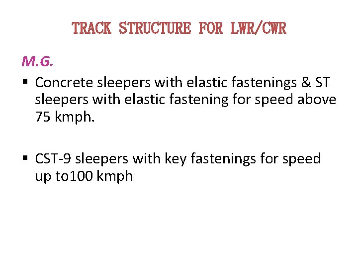
TRACK STRUCTURE FOR LWR/CWR M. G. § Concrete sleepers with elastic fastenings & ST sleepers with elastic fastening for speed above 75 kmph. § CST-9 sleepers with key fastenings for speed up to 100 kmph
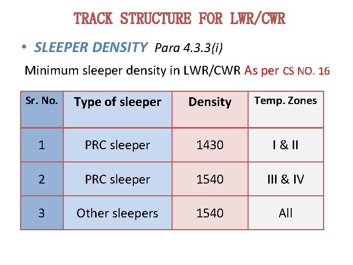
TRACK STRUCTURE FOR LWR/CWR • SLEEPER DENSITY Para 4. 3. 3(i) Minimum sleeper density in LWR/CWR As per CS NO. 16 Sr. No. Type of sleeper Density Temp. Zones 1 PRC sleeper 1430 I & II 2 PRC sleeper 1540 III & IV 3 Other sleepers 1540 All
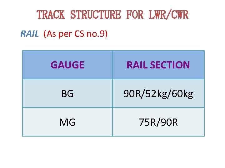
TRACK STRUCTURE FOR LWR/CWR RAIL (As per CS no. 9) GAUGE RAIL SECTION BG 90 R/52 kg/60 kg MG 75 R/90 R
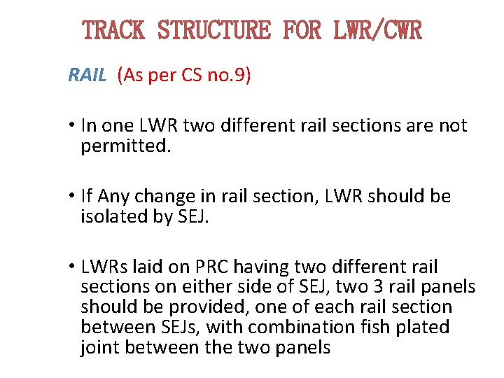
TRACK STRUCTURE FOR LWR/CWR RAIL (As per CS no. 9) • In one LWR two different rail sections are not permitted. • If Any change in rail section, LWR should be isolated by SEJ. • LWRs laid on PRC having two different rail sections on either side of SEJ, two 3 rail panels should be provided, one of each rail section between SEJs, with combination fish plated joint between the two panels
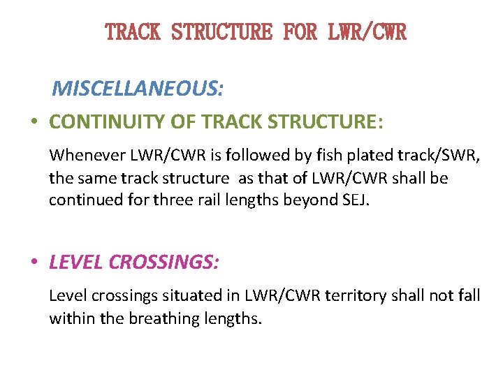
TRACK STRUCTURE FOR LWR/CWR MISCELLANEOUS: • CONTINUITY OF TRACK STRUCTURE: Whenever LWR/CWR is followed by fish plated track/SWR, the same track structure as that of LWR/CWR shall be continued for three rail lengths beyond SEJ. • LEVEL CROSSINGS: Level crossings situated in LWR/CWR territory shall not fall within the breathing lengths.
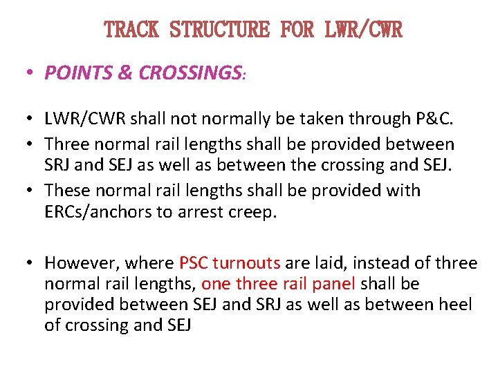
TRACK STRUCTURE FOR LWR/CWR • POINTS & CROSSINGS: • LWR/CWR shall not normally be taken through P&C. • Three normal rail lengths shall be provided between SRJ and SEJ as well as between the crossing and SEJ. • These normal rail lengths shall be provided with ERCs/anchors to arrest creep. • However, where PSC turnouts are laid, instead of three normal rail lengths, one three rail panel shall be provided between SEJ and SRJ as well as between heel of crossing and SEJ
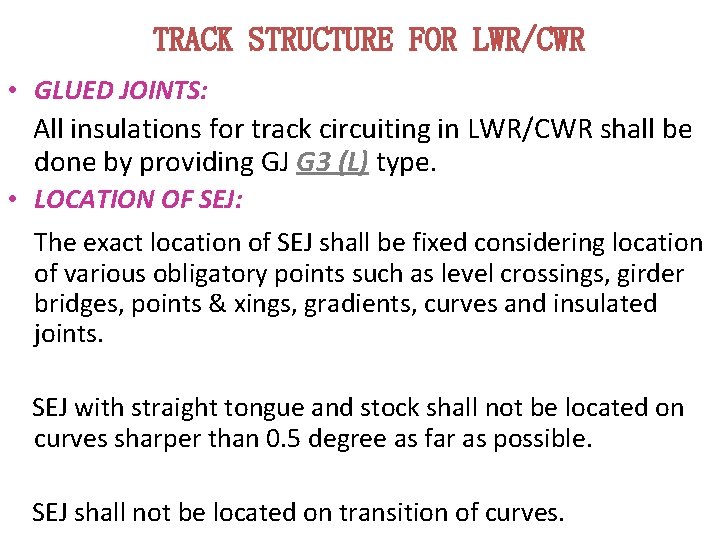
TRACK STRUCTURE FOR LWR/CWR • GLUED JOINTS: All insulations for track circuiting in LWR/CWR shall be done by providing GJ G 3 (L) type. • LOCATION OF SEJ: The exact location of SEJ shall be fixed considering location of various obligatory points such as level crossings, girder bridges, points & xings, gradients, curves and insulated joints. SEJ with straight tongue and stock shall not be located on curves sharper than 0. 5 degree as far as possible. SEJ shall not be located on transition of curves.
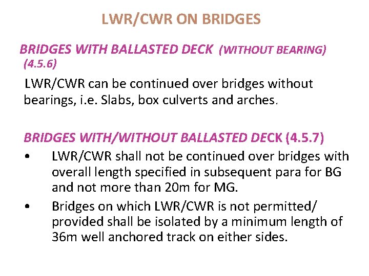
LWR/CWR ON BRIDGES WITH BALLASTED DECK (WITHOUT BEARING) (4. 5. 6) LWR/CWR can be continued over bridges without bearings, i. e. Slabs, box culverts and arches. BRIDGES WITH/WITHOUT BALLASTED DECK (4. 5. 7) • LWR/CWR shall not be continued over bridges with overall length specified in subsequent para for BG and not more than 20 m for MG. • Bridges on which LWR/CWR is not permitted/ provided shall be isolated by a minimum length of 36 m well anchored track on either sides.
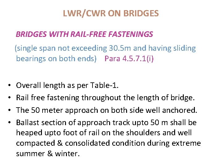
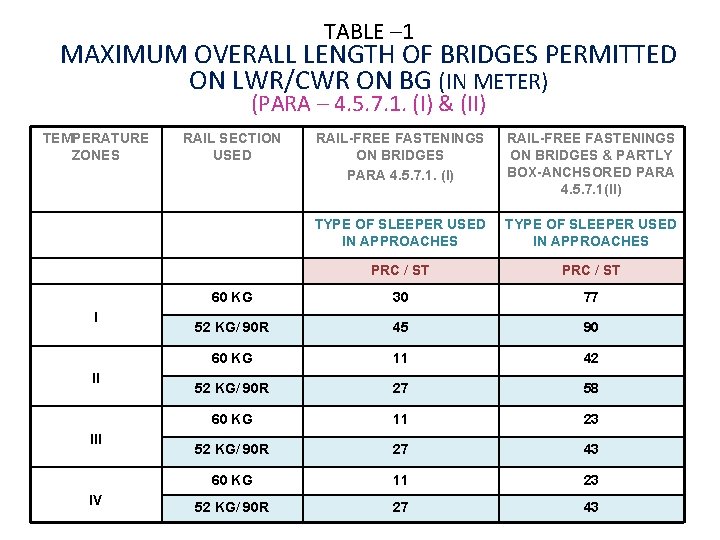
LWR/CWR ON BRIDGES WITH RAIL-FREE FASTENINGS (single span not exceeding 30. 5 m and having sliding bearings on both ends) Para 4. 5. 7. 1(i) • • Overall length as per Table-1. Rail free fastening throughout the length of bridge. The 50 meter approach on both side well anchored. Ballast section of approach track upto 50 m shall be heaped upto foot of rail on the shoulders and well compacted & consolidated condition during extreme summer & winter.
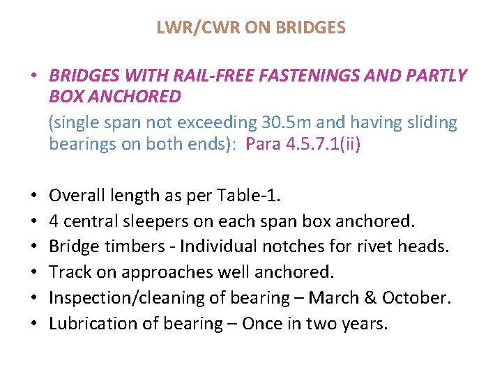
LWR/CWR ON BRIDGES • BRIDGES WITH RAIL-FREE FASTENINGS AND PARTLY BOX ANCHORED (single span not exceeding 30. 5 m and having sliding bearings on both ends): Para 4. 5. 7. 1(ii) • • • Overall length as per Table-1. 4 central sleepers on each span box anchored. Bridge timbers - Individual notches for rivet heads. Track on approaches well anchored. Inspection/cleaning of bearing – March & October. Lubrication of bearing – Once in two years.
TABLE – 1 MAXIMUM OVERALL LENGTH OF BRIDGES PERMITTED ON LWR/CWR ON BG (IN METER) (PARA – 4. 5. 7. 1. (I) & (II) TEMPERATURE ZONES I II IV RAIL SECTION USED RAIL-FREE FASTENINGS ON BRIDGES PARA 4. 5. 7. 1. (I) RAIL-FREE FASTENINGS ON BRIDGES & PARTLY BOX-ANCHSORED PARA 4. 5. 7. 1(II) TYPE OF SLEEPER USED IN APPROACHES PRC / ST 60 KG 30 77 52 KG/ 90 R 45 90 60 KG 11 42 52 KG/ 90 R 27 58 60 KG 11 23 52 KG/ 90 R 27 43
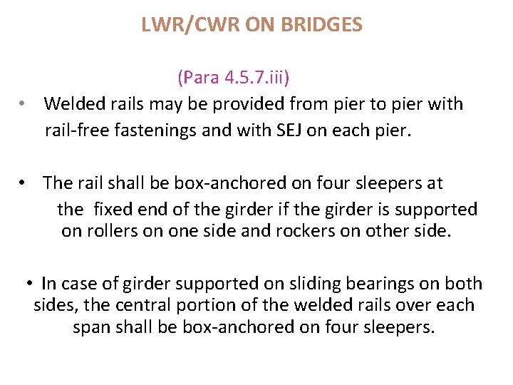
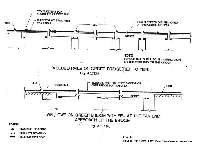
LWR/CWR ON BRIDGES (Para 4. 5. 7. iii) • Welded rails may be provided from pier to pier with rail-free fastenings and with SEJ on each pier. • The rail shall be box-anchored on four sleepers at the fixed end of the girder is supported on rollers on one side and rockers on other side. • In case of girder supported on sliding bearings on both sides, the central portion of the welded rails over each span shall be box-anchored on four sleepers.
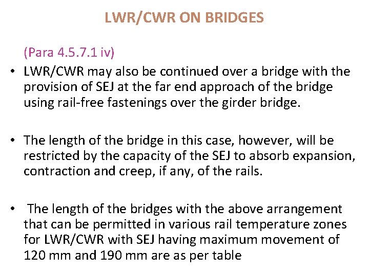
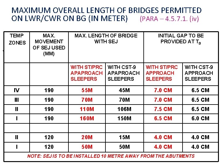
LWR/CWR ON BRIDGES (Para 4. 5. 7. 1 iv) • LWR/CWR may also be continued over a bridge with the provision of SEJ at the far end approach of the bridge using rail-free fastenings over the girder bridge. • The length of the bridge in this case, however, will be restricted by the capacity of the SEJ to absorb expansion, contraction and creep, if any, of the rails. • The length of the bridges with the above arrangement that can be permitted in various rail temperature zones for LWR/CWR with SEJ having maximum movement of 120 mm and 190 mm are as per table
MAXIMUM OVERALL LENGTH OF BRIDGES PERMITTED ON LWR/CWR ON BG (IN METER) (PARA – 4. 5. 7. 1. (iv) . TEMP ZONES MAX. MOVEMENT OF SEJ USED (MM) MAX. LENGTH OF BRIDGE WITH SEJ INITIAL GAP TO BE PROVIDED AT TD WITH ST/PRC APAPROACH SLEEPERS WITH CST-9 APAPROACH SLEEPERS WITH ST/PRC APPROACH SLEEPERS WITH CST-9 APPROACH SLEEPERS IV 190 55 M 45 M 7. 0 CM 6. 5 CM III 190 70 M 7. 0 CM 6. 5 CM II 190 110 M 106 M 7. 5 CM 6. 5 CM I 190 160 M 150 M 6. 5 CM 6. 0 CM II 120 20 M 15 M 4. 0 CM I 120 50 M 4. 0 CM NOTE: SEJ IS TO BE INSTALLED 10 METRE AWAY FROM THE ABUTMENTS
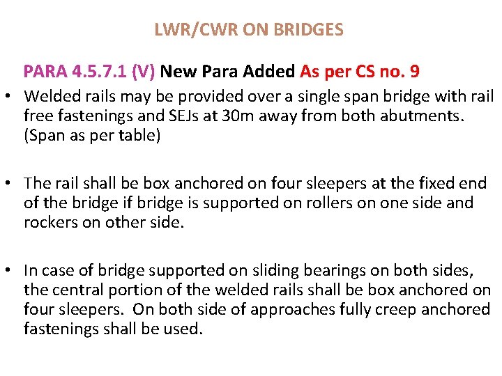
LWR/CWR ON BRIDGES PARA 4. 5. 7. 1 (V) New Para Added As per CS no. 9 • Welded rails may be provided over a single span bridge with rail free fastenings and SEJs at 30 m away from both abutments. (Span as per table) • The rail shall be box anchored on four sleepers at the fixed end of the bridge if bridge is supported on rollers on one side and rockers on other side. • In case of bridge supported on sliding bearings on both sides, the central portion of the welded rails shall be box anchored on four sleepers. On both side of approaches fully creep anchored fastenings shall be used.
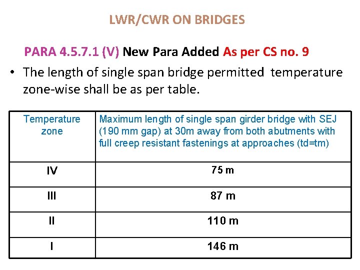
LWR/CWR ON BRIDGES PARA 4. 5. 7. 1 (V) New Para Added As per CS no. 9 • The length of single span bridge permitted temperature zone-wise shall be as per table. Temperature zone Maximum length of single span girder bridge with SEJ (190 mm gap) at 30 m away from both abutments with full creep resistant fastenings at approaches (td=tm) IV 75 m III 87 m II 110 m I 146 m
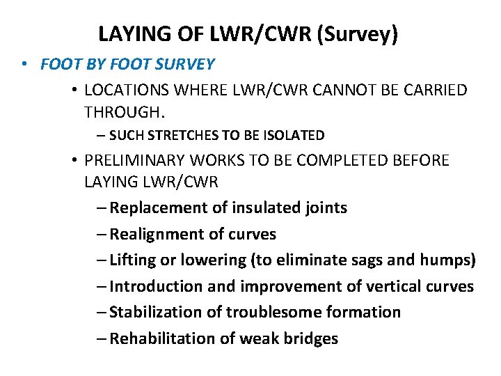
LAYING OF LWR/CWR (Survey) • FOOT BY FOOT SURVEY • LOCATIONS WHERE LWR/CWR CANNOT BE CARRIED THROUGH. – SUCH STRETCHES TO BE ISOLATED • PRELIMINARY WORKS TO BE COMPLETED BEFORE LAYING LWR/CWR – Replacement of insulated joints – Realignment of curves – Lifting or lowering (to eliminate sags and humps) – Introduction and improvement of vertical curves – Stabilization of troublesome formation – Rehabilitation of weak bridges
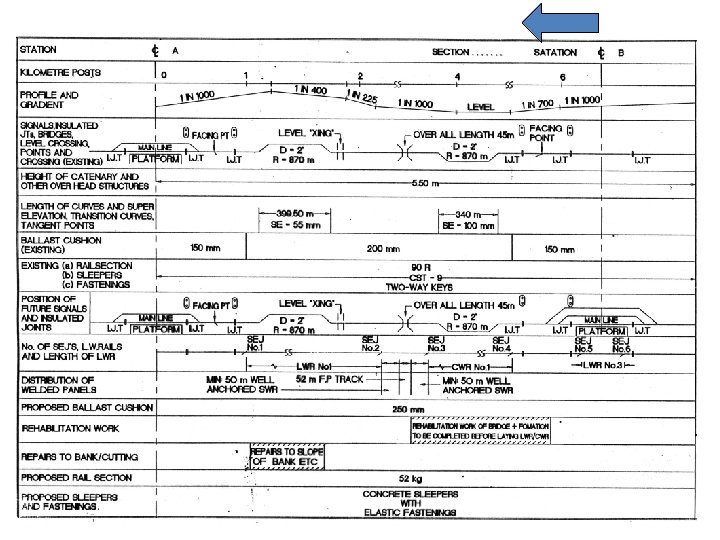
LAYING OF LWR/CWR • A detailed plan shall be made showing the exact locations of SEJs and of various other features like curves, level crossings, bridges, points and crossings, glued joints, gradient, rail section, sleepers, sleeper density • The plans may be prepared to horizontal scale of 1: 5000
MAINTENANCE OF LWR/CWR Regular track maintenance Includes following operations: i) Tamping / packing ii) Lifting iii) Shallow screening / shoulder cleaning iv) Aligning including minor realignment of curve v) Renewal of fastening requiring lifting vii) Maintenance of Buffer rails
Manual Maintenance of LWR/CWR • Not more than 30 sleepers spaces to be opened at a time for through packing or shallow screening • Remaining portion to be tackled after passage of traffic for 24 hours in case of B. G route carrying traffic > 10 GMT • For other route of B. G/M. G – after passage of traffic for two days
Manual Maintenance of LWR/CWR • For alignment correction, shoulder ballast to be removed from end of the sleepers only. • Before opening the crib ballast, shoulder ballast must be put back. • In exceptional circumstances, up to 100 sleeper can be opened in presence of PWI when temperature is likely to remain in the range of td -30 to td +100 C provided fastening are effective and no unusual behavior of SEJs.
Casual renewal of Sleepers • Not more than one sleeper in 30 consecutive sleepers to be replaced at a time. • Adjoining sleeper can be replaced after packing the sleeper renewed earlier. • Work should be done within the maintenance temperature only.
Renewal of Fastening Not requiring lifting: • On one sleeper at a time. • 15 sleepers should be kept intact if more than one sleeper to be tackled. • Minimum level of supervision - Key man. Requiring lifting: • On one sleeper at a time. • 30 sleepers to be kept intact if more than one sleeper to be tackled. • Minimum level of supervision- Gang mate
Maintenance of SEJs • Once in a fortnight – Checking, packing, aligning if necessary, Oiling and greasing of stock rail & tongue rail and tightening of fitting simultaneously. • During daily patrolling, Key man shall keep special watch on all SEJs falling in his beat.
Mechanized maintenance • General lift not exceeding 50 mm in case of concrete sleepers and 25 mm in case of other sleepers. • If lifting is required more than the above limits than lifting to be done in stages with adequate gap in between stages giving time for full consolidation of the previous stage.
Special track Maintenance • TFRThe LWR shall be de-stressed along with TFR. • Deep screening • If temperature range is between td+10 to td-200 C – DS may be done without cutting or temporary destressing. • If range falls out side the above – temporary de-stressing is required at the temperature 100 C below the maximum temperature likely to be attained during the period of work.
Special track Maintenance Contd. … • Deep screening shall be undertaken within 15 days of temporary destressing. • Introduce cold weather patrolling during deep screening period, if temperature falls 300 C bellow td/ temporary destressing temperature. • Deep screening by BCM – As far as possible BCM, tamping machine and DTS shall be deployed in one consist. • After deep screening & consolidation, destressing of LWR shall be undertaken at proper destressing temperature.
Other special Track maintenance Precautions to be taken for Other special track maintenance works (Lowering of track, major realignment of curves, renewal of large number of sleepers, rehabilitation of formation/bridges. ) • Affected length may be isolated from LWR by introducing SEJs / Buffer rails. • After completion of work, destress the affected length at td and join with rest of LWR
Special Equipments for maintenance of LWR/CWR Additional equipments with gangs – A pair of joggled fishplates with bolted clamps – Rail thermometer with marking for temperature ranges for maintenance – Special 1 m long fishplates with screw clamps – Rail closer pieces
INSPECTIONS Para 8. 1. 5 modified As per cs no. 15 • Inspection of gaps at SEJ & creep/movement at centre of LWR/CWR By JE (Pway) – a) Once in fortnight during two coldest & two hottest months of the year at about minimum & maximum temperatures Otherwise once in two months by rotation with SE(Pway). By SE (Pway) – a) Once in fortnight during two coldest & two hottest months of the year at about minimum & maximum temperatures Otherwise once in two months by rotation with JE(Pway).
INSPECTIONS • By Assistant Engineer – • Shall Inspect all SEJs & creep/movement at centre of LWR/CWR, At least once in six months, preferably during coldest & hottest months Para 8. 2. 5 modified As per cs no. 14 AEN will analyse the observation of each LWR/CWR in his jurisdiction and give certificate at the end of LWR/CWR register before onset of summer regarding satisfactory behavior of all LWR/CWRs. DEN/Sr. DEN will scrutinize observations of each LWR/CWR, initial each page and exception report to be submitted to CTE only when his orders are required.
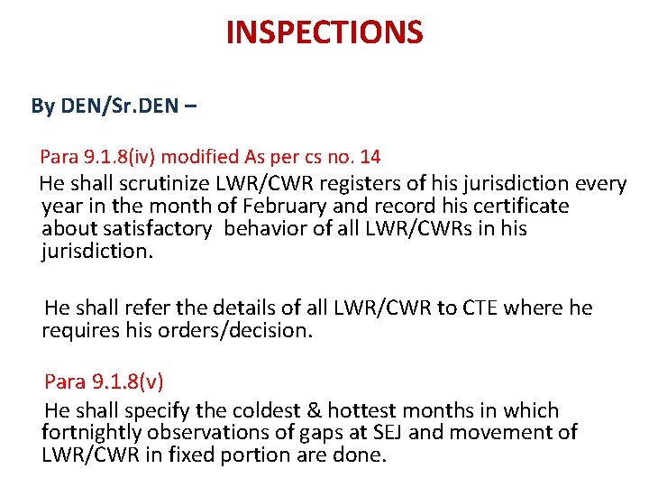
INSPECTIONS • By DEN/Sr. DEN – Para 9. 1. 8(i) modified As per cs no. 14 He shall be responsible for ensuring that AEN & Supervisors working under him are fully conversant and comply with provisions in this manual & such other supplementary instructions issued by PCE from time to time. Para 9. 1. 8(ii) He shall ensure training of staff working on LWR/CWR sections. Para 9. 1. 8(iii) He shall make arrangements for sufficient quantity of ballast required for LWR/CWR sections.
INSPECTIONS By DEN/Sr. DEN – Para 9. 1. 8(iv) modified As per cs no. 14 He shall scrutinize LWR/CWR registers of his jurisdiction every year in the month of February and record his certificate about satisfactory behavior of all LWR/CWRs in his jurisdiction. He shall refer the details of all LWR/CWR to CTE where he requires his orders/decision. Para 9. 1. 8(v) He shall specify the coldest & hottest months in which fortnightly observations of gaps at SEJ and movement of LWR/CWR in fixed portion are done.
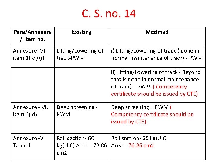
C. S. no. 14 Para/Annexure / Item no. Annexure -VI, item 1( c ) (i) Existing Modified Lifting/Lowering of track-PWM i) Lifting/Lowering of track ( done in normal maintenance of track) - PWM ii) Lifting/Lowering of track ( Beyond that is done in normal maintenance of track) – PWM ( Competency certificate should be issued by CTE) Annexure - VI, item 3( d) Deep screening PWM Deep screening – PWM ( Competency certificate should be issued by CTE) Annexure -V Table 1 Rail section- 60 kg(UIC) Area = 78. 86 Area = 76. 86 cm 2
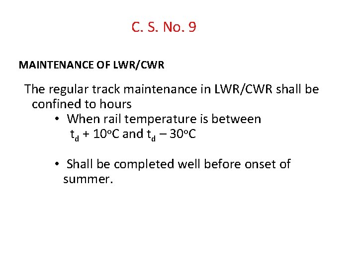
C. S. No. 9 MAINTENANCE OF LWR/CWR The regular track maintenance in LWR/CWR shall be confined to hours • When rail temperature is between td + 10 o. C and td – 30 o. C • Shall be completed well before onset of summer.
THANKS