Laying Of LWR On Sharp Curves And Steep


 Alignment: (a) LWR shall not be laid on")
 2 nd Edition March 2005 1. UIC")
 2 nd Edition March 2005 6. This")
 2 nd Edition March 2005 7. In")


 i.")
 v.")
 in controlling the Behaviour of Continuous Welded Track")
 in controlling the Behaviour of Continuous Welded Track")


 b) c) d) e) f) g)")


 or Rail Neutral")


 1. Buckling is sudden lateral shift in")
 The modified formula for buckling load is")


 Lateral ballast resistance values have")


")
")

 laid in steep gradients of Kasara. Igatpuri and")


 1. Track structure")
 8. Creep post")
 1. LWR/CWR on")


 Track Structure : 60 Kg")


- Slides: 86
Laying Of LWR On Sharp Curves And Steep Gradients Satya Prakash Dean/IRICEN
Problems of Fish Plated Track in Ghat Sections 1. Ghat sections typically have both sharp curves and steep gradients due to hilly terrains. 2. Fish plated joints are discontinuities in track and every passing wheel of rolling stock gives heavy impact load on rails, fastenings, sleepers, ballast and formation. 3. This results in deterioration in track geometry and frequent wear and tear of track components. 4. Frequent maintenance and replacement of worn out components.
Problems of Fish Plated Track in Ghat Sections 6. Fish plated joints exhibit development of bolt hole cracks and rail fractures at fish plated joint. 7. Fish plated joints are easy targets of disgruntled elements for causing sabotage and railway accidents in which many lives have been lost in recent times in addition to causing large scale damage and traffic disruptions. 8. Elimination of fish plated joints also results in an improvement in safety as scope of causing sabotage is reduced considerably. 9. In sharp curves due to high lateral and vertical impact force generated by rolling stock elbows are formed at fish plated joints resulting in further increase in lateral force as a result lurch is felt by passengers travelling in trains.
Problems of Fish Plated Track in Ghat Sections 10. In long and continuous gradients, the rails suffer creep resulting in too little or too much gap at rails joints. 11. Sleepers going out of square straining fastening, dislocating and damaging rubber pads. 12. Free rails creeps more in comparison to short welded rails. 13. Present instructions do not permit laying of LWR on sharp curves and steep gradients. 14. With laying of LWR on such tracks the problem of creep is eliminated or reduced to a large extent.
Provisions of IRPWM Para 326 (2) Alignment: (a) LWR shall not be laid on curves sharper than 440 m radius. However in temperature Zone-I, LWR/CWR may be laid on curves upto 350 m radius (5 0 Curve) with following additional precautions: i. Minimum track structure should be 52 Kg rail on PSC sleepers, M+7 sleeper density with 300 mm clean ballast cushion. ii. Shoulder ballast for curves sharper than 440 m radius should be increased to 600 mm on outside of curve and should be provided for 100 m beyond the tangent point. iii. Reference marks should be provided at every 50 m interval to record creep, if any. iv. Each curve of length greater than 250 m should preferably be provided with SEJ on either side. SEJ should be located in straight track at 100 m away from the tangent point. Para 326(3) Gradient: The steepest permitted grade for LWR/CWR shall be 1 in 100.
Provisions of UIC Code – 720 (R) 2 nd Edition March 2005 1. UIC 720 R 2 nd edition leaflet on ‘Laying and Maintenance of CWR Track’ issued in March 2005 contains guidelines for use, installation and inspection of ballasted track with CWR. 2. It lists the associated safety criteria. 3. It is based on practical experience of several railways and large number of test and theoretical studies carried out over a period of more than 40 years. 4. It includes result of international work on this topic carried out by ERRI committee D 202. 5. As per its para 2. 5 on alignment “The minimum curve radius in which CWR track may be safely installed depends on the rail section, the fastenings, the type of sleepers, the ballast profile and the anticipated longitudinal thermal stresses. CWR may be installed on curves sharper than 300 m radius provided special measures, such as fitting anchoring devices to sleepers, are taken. ”
Provisions of UIC Code – 720 (R) 2 nd Edition March 2005 6. This leaflet does not lay down any restriction for installation of CWR on gradients except for precautions laid down in para 3. 5 on Tunnels, gradients and braking. “In locations where large uneven changes in rail temperature are experienced, longitudinal movement of sleepers in ballast or of rails relative to sleepers may alter the original stress-free temperature of track. The effect will depend on characteristics of ballast, the type of sleepers or the creep resistance of fastenings. The longitudinal force generated by vehicle may produce similar effect. Such effect may occur particularly: i. In the vicinity of tunnel portal and in deep cuttings, ii. On rising and falling gradients, iii. In long continuous curves, iv. The tracks where eddy current brakes are in use. ”
Provisions of UIC Code – 720 (R) 2 nd Edition March 2005 7. In order to minimise the effect on stress- free temperature and the consequent reduction in stability of CWR track, the above situations shall be subjected to particular careful monitoring. 8. Appropriate additional measures shall be taken to improve the stability of the track where they are considered necessary.
Applicability of UIC Code on Indian Railway 1. Indian Railway is member of UIC and is associated in number of its studies. 2. Though this UIC code is based mainly on experience of European countries, North America and experimental and theoretical work done in Europe and USA but its provisions can be used on Indian Railway. 3. These provisions are based on experience and trials conducted on Standard Gauge (SG) track. 4. Its provisions can be used on Indian Railway as in UIC code 720 R’s para 3. 7 regarding gauge it has been mentioned that “Variations in gauge have only a minor effect on track stability and can usually be ignored in this context. ” 5. In fact with wide frame, longer and heavier sleepers, Broad Gauge (BG) track’s resistance to lateral instability will be more than that of Standard Gauge (SG) track. 6. Thus provisions of UIC code can be safety applied on Indian Railways as being done in case of UIC 774 -R.
Literature Review
Track Stability and Buckling – Rail Stress Management : Zayne Kristian Ole i. Buckling is sudden track misalignment caused by temperature and/ or rail creep induced stresses which require placement of speed restriction and/ or immediate attention by infrastructure maintainer to allow trains to pass safely. ii. Queensland Rails (Australia)’s Civil Engineering Standards (CETS) which conforms to requirements of Australian Standards AS: 4292 on Railway Safety Management and National Code of Practices, specifies limit on creep of 50 mm into or out of 500 m track, after which rails shall be restressed. 50 mm creep into 500 m rail is equivalent to an 8. 550 C reduction in Rail Neutral Temperature (RNT). iii. Lateral imperfection at joint or defective weld results in weak spot as stiffness about vertical axis at joint or defective weld is less than that of the adjacent rail, creating a trigger point for a buckle.
Track Stability and Buckling – Rail Stress Management : Zayne Kristian Ole iv. Change in RNT is caused by creep, curve breathing, track settlement and maintenance practices i. e. welding. v. Rolling out of rail is elongation and plastic deformation of top layer of rail head caused by traffic. Rolling out of rail causes residual tensile stresses in new rail to change to compression due top rolling contact. Railways of Australia (ROA 1988) suggest that this can lower RNT by upto 90 C. vi. Dynamic loading from train is a cause factor in occurrence of buckling. The wheels of fast moving train and heavily laden train tends to generate a dynamic uplift wave in rail and this often triggers the buckle process. Lateral forces exerted by wheel on rail will induce bending stress and trigger a buckle. Additional load on rail is caused by hunting and nosing on a tangent and curved track. Heavy braking such as emergency braking is a vehicle load that may trigger buckle.
Track Stability and Buckling – Rail Stress Management : Zayne Kristian Ole vii. As per ROA 1988 the contribution of lateral ballast resistance is as under: Rail =12 -18% Sleepers and Fasteners = 13 -37% Ballast = 50 -70% vii. If SFT (Stress Free Temperature) variation from its designed neutral temperature exceeds + 100 C, the rails must be restressed. viii. To reduce temperature of rails ROA 1988 recommends planting of shady trees or to more immediate effect, painting the rail white which ROA suggests can result in rail temperatures 50 C – 70 C less than unpainted rail on a clear hot day.
Creep Trends Cyclic Fluctuations: - Cyclic fluctuations in creep may not have appreciable cumulative effect on RNT at location that displays this trend. Cyclic fluctuation of creep may have short term influence on RNT depending upon magnitude and direction of displacement and proximity to fixed structure locations displaying excessive creep are identified as that require further investigation.
Creep Trends Non Recovering Creep: - Tendency of rail to continually displace in one direction will cause accumulation of compressive stresses in rail, lowering RNT. Accumulation of compressive stress and inherent initial curvature of rail road constitute conditions that are conducive to buckling.
Creep Trends Diverging rails: - Disparity in rate and extent of creep in left and right rail will give rise to differential strain in rails, magnitude and sense of induced forces on rails may result in development of moment couple. The development of moment couple arising from disparity in longitudinal forces in left and right rail will cause a small lateral deflection, introducing eccentricity and an incidental moment under application of axial force. This may cause the track to buckle. Disparity in rate and extent of creep in left and right rail also causes misalignment of sleepers as a result of bending moment applied to the rails, reducing tracks ability to resist buckling.
Creep Trends •
SFT and Stability of CWR Track – Rail Safety and Standard Board (UK) i. It is recognized fact that rail creeps longitudinally, no matter how efficient the fixing method is. ii. Braking, acceleration, maintenance procedure i. e. tamping, extreme weather and temperature variation all contribute to rail movement i. e. creep. iii. Network Rail (UK) states that 34% of all track buckles occur either within switch and crossing unit or within 100 m of adjacent plain track. iv. Works reducing ballast resistance: Tamping with lift < 25 mm = 40% Design Tamping = 65% Stone blowing = 50% Ballast Cleaning = 70%
SFT and Stability of CWR Track – Rail Safety and Standard Board (UK) v. Destressing Temperature Network rail (UK) = 270 C Irish rail = 230 C Dutch Railway = 250 C Deutsche Bahn AG = 23+30 C US Rail Road = 34 -460 C vi. Good Maintenance Practices (a) Maintain Good Ballast Profile (b) Avoid disturbance to track, particularly in hot weather (c) Beware of locations where rail creeps and take precautionary measures (d) Avoid cutting CWR without restoring stress (e) Maintain proper designed alignment of curves (f) Maintain good rail geometry vii. Reducing ballast shoulder height from designed 125 mm to level of sleeper ends is likely to reduce lateral resistance of track by around 20% and that is likely to reduce critical rail temperature (CRT) by 30 C.
Effectiveness of Southern Pacific Lines (USA) in controlling the Behaviour of Continuous Welded Track – David T Wickersham i. ii. iv. v. Southern Pacific line (in USA) runs through Granite Mountains, hot and arid deserts, humid and marshy swamps. Track runs through areas where record snowfall occurs and the areas that receive greatest and least amount of rain fall. Geometry of track includes 150 curves and 3. 5% (1 in 28. 6) gradient. Temperature ranges from 1560 F (68. 90 C) to – 500 F (-45. 60 C). CWR is used in all these areas. It has been learned from track buckling research that track buckling occur when rail temperature increase to 600 F (20. 5560 C) or more above adjusted temperature.
Effectiveness of Southern Pacific Lines (USA) in controlling the Behaviour of Continuous Welded Track – David T Wickersham •
Improved Knowledge of CWR – Conraad Esveld i. In 1992 UIC commissioned a study from ERRI (European Rail Research Institute) entitled ‘Improved Knowledge of CWR’ and the work was assigned to ‘ERRI D 202’ specialist committee. There were basically four parts of the work: a) b) c) d) Development of theoretical knowledge. Experimental work to determine input values for models. Revision of UIC Leaflet on CWR Non-destructive measurement of longitudinal rail forces. ii. Three models were developed a) b) c) CWERRI: Analysis track stability in combination with longitudinal and vertical forces including dynamic effect and yielding of ballast under combined load situations. LONGIN: Permits analysis of creep phenomenon under longitudinal train loads and also models curve breathing. TURN: A program which allows analysis of turnouts in combination with finite element package ALGOR. iii. These models were developed in TU Delft Netherland TU Krakow’ Poland.
Improved Knowledge of CWR – Conraad Esveld iv. Experimental work was primarily focused on obtaining track resistance data. One of the objectives also was to link European data to test data from single tie experiments in North America. v. In the study priority was given to develop models to describe behavior of long bridges, switches, tight curves, both from aspect of longitudinal forces and lateral stability, also taking into consideration dynamic and rheological behavior. Systemic check on stresses in track, safety rules/ criteria/ margin, unified method. Influence of parameters like gauge, track component and track quality. vi. CWERRI program was developed by TU Delft in Netherland contained functionality with respect to lateral and vertical stability of curves track and longitudinal, lateral and vertical forces. The program is able to model multi span bridges with parallel tracks loaded by moving train set. The basic features of model are as under:
Improved Knowledge of CWR – Conraad Esveld a) b) c) d) e) f) g) h) i) Three dimensional modeling and calculation tools. Longitudinal, lateral and vertical forces. Lateral and vertical track stability Thermal and mechanical loads. Complete train loads, taking uplift wave into account. Three dimensional ballast yield, taking influence of vertical load into account. Track/ bridge interaction, including effect of end rotation. Multi span bridges with parallel tracks. Buckling Analysis of Curves Track. vii. Using CWERRI Model, a sensitivity analysis was carried out on track of following structure by varying parameters such as half wave length of misalignment, curve radius, peak and limit lateral ballast resistance and torsional stiffness.
Top View of Track Model Curve radius = 400 m, half wave length of misalignment = 9. 144 m, amplitude= 0. 0381 m (38. 1 mm), rail = AREA 136 (equivalent to 68 Kg/m), sleeper spacing = 0. 61 m, Vertical stiffness of track = 68900 KN/m
Model of lateral ballast behavior under different vertical loadings The track was loaded vertically by hopper car with two bogies represented by four vertical axle load of 293 KN each in following configuration. Vertical load applied on track model (Fv= 293 KN)
Lateral deformation in the middle of the model Track was thermally loaded by increasing temperature from 00 C to 1000 C. The deformation at centre of model against temperature rise is presented in graph below The plot is characterised by 2 points. The first point is Tb, max (49. 40 C) at which buckling starts and which is the highest point in the figure. After this temperature drops and deformations grow rapidly. The second point is Tb, min (33. 50 C) that occurs after buckling has started.
Sensitivity Analysis With the above track model sensitivity analysis was conducted through CWERRI Program, by varying one of the parameters over practical range while keeping all other parameters constant at fixed value. The parameters, fixed values and range over which they were varied are as under: Parameters in sensitivity study
Influence of curve radius
Influence of lateral peak resistance
Influence of longitudinal stiffness
Influence of Torsional stiffness of sleepers and Fastening system
Influence of amplitude of misalignment
Influence of half wave length of misalignment
Long Term behaviour of CWR Track 1. Neutral Rail Temperature (NRT) or Rail Neutral Temperature (RNT) may change in time in continuously welded rail tracks. Changes may be expected in places where rail creep may occur in following conditions a) train acceleration, braking especially in combination with gradients b) in sharp curves as an effect of inward/ outward movement c) as a consequence of track maintenance operations like track tamping, destressing, ballast cleaning
Long Term behaviour of CWR Track 2. As a result of existing work on long term CWR track, response may be summarized by following statements. a) Changes in RNT (Rail Neutral Temperature) during service may reach + 100 C. General tendency was for RNT to shift downward. b) For typical train loads and track structure, the longitudinal residual displacements due to track creep are in the range of few millimeters. In particular cases of very heavy trains, longitudinal residual displacements may reach about 500 mm/ year. c) Thermal loading of turnouts and adjoining zones may be characterized as under: d) Longitudinal force in switch rail zone may increase upto 50% in relation to thermal force in straight track. e) A longitudinal displacement in straight track reaches 2 to 10 mm. It means that special protection (in particular for turnouts on wooden sleepers) must be introduced. 3. Longitudinal track response due to elongations/ shortening of bridge deck practically does not depend on service time.
Long Term behaviour of CWR Track 4. In the study of long term behavior of 21 track sections in Poland Hungary with different type of track structure with sharp curves and steep gradients, passenger and freight train operations, over 9 months following conclusions have been drawn. a) Changes in RNT during service reach 50 C to 200 C. b) Changes in RNT during service had in general formed random variation without distinct trend. c) CWR track with concrete sleepers gave more stable RNT in relation to track with wooden sleepers. d) The average RNT values calculated for test sections were not constant in curves but shown the annual periodicity of rail temperatures. e) Use of devices with RNT measurement accuracy at + 30 C and displacement accuracy of about 0. 1 to 0. 2 mm are practically sufficient for investigation of CWR track behavior without considering local effect (e. g. distribution of residual stresses in rail cross section, local changes of rail material microstructure). f) To measure the actual RNT of a given section before major track maintenance operations to enable the selection of most suitable technology.
Short- term Track Response
Long- term track response – changes in RNT
Long- term changes in RNT – Along the test section
Static Buckling- Factor of Safety
Factor of Safety against Buckling (Static Buckling) 1. Buckling is sudden lateral shift in track alignment to relieve built up of compressive forces in rail caused by high rail temperature i. e. increase in rail temperature above stress free temperature, reduction in rail neutral temperature (Stress Free Temperature) and reduction in lateral ballast resistance. Straight track normally buckles in wave form i. e. ‘S’ wave and sharp curves normally buckles in ‘C’ shape. The longitudinal load required to buckle track is given by following formula 1: Buckling Load = π2 EIs/l 2 + π2 C/16 D (π l/q)1/2 + l 2 R/ (π2 q) 2. In the above formula the π2 EIs/l 2 represents contribution of rails toward resistance against bucking, the term π2 C/16 D (√π l/q) represents contribution of sleepers and fastening towards resistance. These two terms together represents track frame resistance which is determined experimentally which has been done in RDSO’s Civil Engineering report no. C-152 (1976). The same has recently been determined for present day sleepers and fastening system in RDSO’s report no. TM 131 (2009) for 60 Kg rails and TM 120 (2009) for 52 Kg rails.
Factor of Safety against Buckling (Static Buckling) The modified formula for buckling load is as under: Buckling Load (P) = π2 Eeq/l 2 + l 2 R/( π2 q) Eeq = Track Frame resistance for particular half wave length of misalignment l = Half wave length of buckled track R= Lateral Ballast Resistance q = misalignment in track over half wave length l in curves the ballast resistance is reduced as under: R= R’ – 2 A E α Δ t/ r R’ = Lateral Ballast Resistance of straight track A = Sectional Area of Rail E = Modulus of elasticity of rail steel α = Coefficient of linear expansion Δ t = Increase in rail temperature above stress free temperature r = Radius of curve
Factor of Safety against Buckling 3. Buckling load is calculated for number of half wave lengths i. e. 5 m, 6 m, 7 m, 8 m etc. and minimum buckling load is determined. 4. Factor of Safety against buckling = minimum buckling load / Maximum compressive force. 5. Maximum Compressive force = 2 A E α Δ t 6. Factor of safety against buckling = {π2 Eeq/l 2 + l 2 R/( π2 q)} / 2 A E α Δ t
Track Frame Resistance as per RDSO Report TM-131 of 2009 The value of frame resistance has been taken from latest RDSO’s report No. TM – 131 of 2009 (for 60 Kg, PSC sleepers and ERC Mark- III). The relevant values are as under: SN Span Eeq in (tm 2) for (m) Sleeper Spacing of 55 Sleeper Spacing of 65 cm c/c 60 cm c/c 1 5 322 309 293 2 6 372 346 316 3 7 442 376 366 4 8 557 436 391
Lateral Ballast Resistance as per RDSO Report TM/TL/62 (2009) Lateral ballast resistance values have been taken from latest RDSO report no. TM/TL/62 (2009). Sleeper Lateral Ballast Resistance Density in After Temping Consolidated track No. /Km Kg/Sleeper Kg/m KN/m 1540 876 1348 13. 22 960 1476 14. 5 1660 910 1517 14. 9 1818 865 1572 15. 4
Factor of Safety against Buckling Track Structure : 60 Kg Rails & PSC Sleepers at 60 Cm Spacing Lateral Ballast Resistance ( Tamped Track) in Kg/m= 1517 Half Wavelength of Buckling (m)= 5 Corresponding Frame Resistance (EIQ) in tm 2= Sectional Area of rail(cm 2)= Misalignment (in mm)= 15 SN 1 2 3 4 5 6 7 8 9 10 11 Degree. 0. 5 1 2 3 4 5 5. 25 6 7 8 8. 75 Radius (m) Tmax-Td 3500. 00 20 1750. 00 20 875. 00 20 583. 33 20 437. 50 20 350. 00 20 333. 33 20 291. 67 20 250. 00 20 218. 75 20 200. 00 20 76. 86 E (in Kg/mm 2)= α = 2. 15 E+06 309 1. 15 E-05 Temperature Zone I II FOS 4. 63 4. 60 4. 54 4. 48 4. 42 4. 36 4. 35 4. 30 4. 24 4. 18 4. 13 Tmax-Td 25 25 25 III FOS 3. 70 3. 67 3. 61 3. 55 3. 49 3. 43 3. 41 3. 37 3. 31 3. 25 3. 20 Tmax-Td 30 30 30 FOS 3. 08 3. 05 2. 99 2. 93 2. 87 2. 81 2. 79 2. 75 2. 68 2. 62 2. 58 IV Tmax-Td 33 33 33 FOS 2. 80 2. 77 2. 71 2. 64 2. 58 2. 52 2. 51 2. 46 2. 40 2. 34 2. 30
Factor of Safety against Buckling for Curves 5. 00 4. 50 4. 00 3. 50 FOS III FOS IV 3. 00 FOS 2. 50 2. 00 1. 50 1. 00 0. 50 0. 00 0. 5 1 2 3 4 5 5. 25 6 Degree of Curve 7 8 8. 75 FOS against buckling reduced marginally with reduction in radius of curve where as it reduced sharply with maximum temperature increase above stress free temperature possible for different temperature zones in India. For 80 curve, FOS against buckling is 4. 18 for Zone I and 2. 34 for Zone IV. Similarly for 5. 250 curve, FOS against buckling is 4. 35 for Zone I and 2. 51 for Zone IV.
Safety Criteria - UIC 720 -R
Safety Criteria as per UIC Code- 720 R and its evaluation on IR tracks 1. The basic premise for CWR buckling safety assurance lies in the performance based requirement. 2. CWR track shall have the buckling strength required to withstand the environmentally and operationally imposed loads for range of expected operating conditions. 3. Safety assessment is conducted through direct application of safety analysis model. 4. The model is used to establish a set of parametric envelop, which can be used as safety guidelines. 5. CWERRI model (program) was developed by ERRI under aegis of UIC and CWRBUCKLE model (program) was developed under the aegis of DOT (Department of Transportation)/ FRA (Federal Railroad Administration), USA, which have undergone rigorous test validations, are used. 6. These models predict the buckling response characteristics, based on which safety concept can be developed.
Safety Criteria as per UIC Code- 720 R and its evaluation on IR tracks 7. Consistent with buckling safety assurance statement, it is required to find ‘allowable or permissible temperature increase’, Tall, which should be larger than anticipated maximum rail temperature increase referenced to the stress free temperature i. e. T all > (Tmax – Tn) 8. Tall can be considered as the “required buckling strength” which is dependent upon governing track and vehicle parameters. 9. Tall can be derived by applying appropriate safety criteria to the analytically determined buckling response curves or it can be empirically determined by dynamic buckling tests. 10. In the above formula Tn is not the installation of the fastening temperature Tf, but the actual value in service life of CWR, which is actually different due to changes induced by rail/ track kinematics and maintenance actions.
Safety Criteria as per UIC Code- 720 R 10. In the absence of non-destructive techniques to determine Tn, a ‘safety factor’ is usually established to account for stress free temperature variation. The stress free temperature is given as under: Tn = Tf - SFTN 11. Where Tf is rail fastening or installation temperature and SFTN is stress free temperature variation safety factor. For UIC tracks, the recommended values for SFTN are in the range of 5 -100 C. 12. Existing buckling safety analysis models such as “CWR-BUCKLE” and “CWERRI” programs predict the upper and lower critical temperatures, and safe allowable temperature increase value for given user input parameters. 13. The results of calculations with CWERRI are expressed in terms of the temperature of the rail above normal stress free temperature (SFT). Normally, there is an area between two limits (Tb, min and Tb, max) wherein buckling can occur.
Temperature Vs displacement for good ballast and poor ballast
Buckling Energy concept illustration Parameters Rail: UIC 60 Sleepers: Concrete Radius: 300 m Misalignment: 12 mm in 8 m Torsional Resistance: Medium Longitudinal Resistance: Medium Axle Load: UIC/D 4 In the absence of detailed analysis with actual track and vehicle parameter using CWERRI or CWR-BUCKLE programme, the above chart can be used for estimating Tb, min and Tb, max.
Safety Criteria as per UIC Code- 720 R and its evaluation on IR tracks 14. For above parameters Tb, min can be estimated as 45. 450 C and Tb, max can be estimated as 96. 360 C. 15. The misalignment taken in above parameter is 12 mm on 8 m half wavelength whereas as per table of para 6. 7 (1) of IRPWM misalignment above 5 mm on 7. 2 m chord is considered in ‘C’ category. 16. The normally machine maintained curved will have track misalignment lower than 12 mm on 8 m chord. 17. Concrete sleepers with full complement of ballast will at least have medium longitudinal and lateral resistance. 18. Axle load of UIC/ D 4 is similar to CC+8 loading running on Indian Railways. Torsional resistance of IR fastening i. e. ERC Mark-III on concrete sleepers can be considered as medium.
Configuration of UIC/ D 4 loading as per UIC 700
Parameters Rail: UIC 60, Axle Load: UIC/D 4 Misalignment: 12 mm in 8 m Sleeper Type: Concrete Torsional Resistance: Medium Longitudinal Resistance: Medium NB: Estimates on lateral resistance ranges: Tamped to 0. 2 MGT ≈ 12 – 18 KN/m Stabilized (0. 2 to 1 MGT) ≈ 19 – 22 KN/m Consolidated ≈ 23 – 28 KN/m Tall i. e. allowable temperature increase above stress free temperature this chart (given on page 30 of UIC Code 720 R) can be used for safety criteria: ϗ = Tall - (Tmax -Tn) > 0
Buckling safety limits for CWR tracks based on Level 1 Safety criterion
Safety Criteria definition in terms of “allowable temperature increase” for safety level 1 and 2
Estimation of Tall for curved track of radius 325 m and 200 m For ballast resistance of 15 KN/m for tamped track for 60 Kg, PSC @ 60 cm c/c as per latest RDSO report No. TM/TL/ 62 of 2009, the allowable temperature increase can be estimated from above chart as 430 C for curved track of 325 m radius and 410 C for curved track of 200 m radius
Case of KK line of East Coast Railway Sharpest curve is 80 i. e. 218 m, minimum temperature = 70 C, maximum temperature = 520 C, mean temperature = 29. 50 C i. e. 300 C. If td is kept as tm+5, td comes to 300 C i. e. Tf = 350 C Rail neutral Temperature Tn= Tf- SFTN As per appendix A. 2 of UIC Code 720 R recommended value to SFTN is between 5 0 C - 100 C Taking maximum SFTN value as 100 C as sharp curve is associated with steep gradients. Tn = 35 -10=250 C For Tall = 410 C from figure 3 of UIC Code for level 1 safety for curved track of radius 200 m, For curved track of 218 m radius, Tall can be safely taken as 410 C. maximum permissible temperature for 80 curves comes as Tmax, (permissible) = 25 + 41 = 660 C Whereas maximum temperature in above section is 520 C. Thus LWR on curved track of radius 218 m is safe. Furthere is margin of 140 C for any abnormal variation in rail neutral temperature and reduction in ballast resistance due to ballast deficiency and track maintenance operations over and above SFTN (safety Factor for Neutral Temperature) of 10 0 C.
Trial of LWRs on sharp curves and steep gradients In KK (Kottavalsa – Kirandul) line of East Coast Railway, LWRs have been laid in sharp curves upto 80 and gradients upto 1 in 60 since 2001 on trial basis the details of these LWRs are as under: SN Section Location Sharpest Steepest Track curve Gradient Structure Laid on Temp Zone td Displacement at Curve Centre 1 BGHU Yard KVLSSMLG ARKSMLG KVLSSMLG 72/173/21 89/2790/17 98/9102/4 88/1787/18 92/5 -91/4 80 1: 60 2001 6. 50 1: 60 60 Kg, PSC @1818/Km do 2003 I (70 C 520 C) do 50 do 80 1: 60 2003 do 60 1: 60 60 Kg, PSC @1660/Km 60 Kg, PSC @1818/Km do 30 LR= +1 RR=+10 35 LR=-1 RR=-3 33 2005 do 2 3 4 5 LR=-2 RR=-4 42 LR=0 RR=-1
Comparison of benefits of LWR experienced in Trial SN Parameter Before (fish plated track) After (LWR track) 1 NA Nil. However as precautionary measure all SKV welds have been joggled fish plated with 4 bolts NR (Not Required) NR NR NR NR. No appreciable creep noticed Negligible wear i. e. about 1 mm/year 2 3 Special Maintenance inputs required/ demanded for LWR Frequency of change of GRSP (i) At joints (ii) At shoulder 6 7 8 ERC Renewal (i) At joints (ii) At shoulder GFN Liner Renewal (i) At joints (ii) At shoulder MS Liner Renewal (i) At joints (ii) At shoulder Frequency of joint packing Frequency of pulling back of rails Rail Wear (lateral) 9 Rail Fracture 4 5 10 Weld Failures Every 1. Months 2. Months Every 4 -5 months 6 months -1 year Every 15 days – 1 month 6 months – 1 year Every 1 year 2 years Every 2 months Every month 6 -7 mm every 3 years More vulnerable near joints. On an average 1 - NIL so far 2 per year in each LWR track length NIL so far
Case of Kasara –Igatpuri and Lonavala ghat sections of Central Railway Sharpest curve 5. 250 i. e. 333 m radius, minimum temperature = 70 C, maximum temperature = 570 C, mean temperature = 320 C. If td is kept as tm+5 , td comes to 370 C i. e. Tf = 370 C Rail neutral Temperature Tn= Tf- SFTN Taking maximum SFTN value (from the range of 50 C-100 C suggested in UIC 720 R) as 100 C as sharp curve is associated with steep gradients. Tn = 37 -10=270 C For Tall = 430 C (taken from Figure 3 of UIC Code for 300 m curves radius), maximum permissible temperature for 5. 250 curves comes as Tmax, (permissible) = 27 + 43 = 700 C Whereas maximum temperature in above sections is 570 C. Thus LWR on curved track of radius 325 m is safe. Furthere is margin of 130 C for any abnormal variation in rail neutral temperature and reduction in ballast resistance due to ballast deficiency and track maintenance operations over and above SFTN (safety Factor for Neutral Temperature) of 100 C.
Details of LWR (10/20 Rail Panels) laid in steep gradients of Kasara. Igatpuri and Karjat –Lonavala section of Central Railway SN Section Location Length (Km) Road 1 2 3 4 Kasara-IGP do Do Do 121. 43 -122. 75 124 -124. 8 129. 32 -130. 2 131. 33 -132. 0 1. 32 0. 88 0. 75 DN DN 5 Do 134. 9 -135. 75 0. 85 DN 6 Do 121. 43 -122. 75 1. 32 Mid 7 Do 124. 1 -124. 8 0. 7 Mid 8 Do 126. 75 -131. 05 2. 21 Mid 9 Do 135. 1 -135. 75 0. 65 Mid 10 Do 121. 43 -122. 75 1. 32 UP 11 Do 124. 1 -124. 8 0. 7 UP 12 Do 124. 75 -130. 75 2. 91 UP 13 Do 135. 1 -135. 75 0. 65 UP Steepest Gradient 1: 37 Track Structure 60 Kg, PSC @1660/Km Central Railway has reported satisfactory behaviour of these LWRs since laying. Since laying of 10/20 rail panels creep has reduced considerably and there is much relief in maintenance of track.
Effect of steep Gradient on CWR Track stability 1. On gradient, the track is vertically inclined on which train move, train weight, tractive effort and braking force act in downward direction, trying to pull the train down the slope. 2. These forces are tangentially applied to the rails which transfers them to the sleepers through fastenings, then to ballast and ultimately to formation and earth. 3. Standard track consisting of rails, fastening, sleepers and ballast is designed to interact to resist longitudinal movement of rails. 4. If the fastenings have adequate creep resistance, these forces gets efficiently transferred to formation. However due to uplift wave, track may suffer creep. 5. The accumulated creep causes shortening/ lengthening of rails. The shortening of rails results in building up of compressive force consequently lowering of Stress Free Temperature (SFT) or Rail Neutral Temperature (RNT). 6. The destressing temperature need to be judiciously chosen so that there is adequate margin i. e. track has adequate buckling strength at maximum anticipated temperature.
Effect of steep Gradient on CWR Track stability 7. 50 mm of creep into 500 m rail length results in reduction of RNT by 8. 68 0 C. 8. It is thus imperative to ensure full complement of ballast and in case loosing of ballast is noticed, adequate speed restriction should be imposed. 9. UIC Code does not lay down any restriction in laying CWR on steep gradients. Longitudinal forces generated by vehicle may alter stress free temperature which needs to be minimised by careful monitoring. 10. Appropriate measures to ensure stability of track shall be taken where considered necessary.
Trial Instructions of RDSO
Trial of LWR on sharp curves and steep gradients 1. Detailed study was conducted by RDSO and Report CT-30 of August 2013 was submitted to Railway Board on 30. 8. 2013. Report was circulated to Zonal Railways on 6. 9. 2013 for conducting trial and submitting performance report. 2. This item was discussed in 84 th TSC held in 2013, in which provision of cross frame and USFD testing of non-gauge face of outer rail on curves sharper than 50 was recommended. The same was approved by Railway Board. 3. Based on recommendation of 84 th TSC, report was modified on conducting trial for determining frame resistance after provision of bracing arrangement in RDSO. 4. Modified Report CT-130 along with drawing of bracing arrangement was submitted to Railway Board on 28. 12. 2015. The same was approved by Railway Board on 17. 01. 2018. Based on this report trial instructions were issued by RDSO vide letter dated 25. 8. 2018. Trial period is 2 Yrs.
Trial Instructions (for continuation of LWR on curves sharper than 40) 1. Track structure shall be minimum 60 Kg 90 UTS, PSC sleepers at minimum 1540/Km density with elastic fastenings. 2. Full ballast as per LWR Manual and full complement of fittings. 3. Joggling of all good AT and FB welds with 4 clamps. 4. Joggling of defective AT and FB welds with 2 clamps and 2 far end bolts. 5. Work of realignment of curves, lifting and lowering of track, improvement of vertical curves, stabilisation of troublesome formation shall be completed before laying LWR. 6. Vertical and lateral wear shall not exceed 8 mm and 6 mm respectively. 7. Alignment defect on curves and approaches are within 10 mm on 10 m chord.
Trial Instructions (for continuation of LWR on curves sharper than 40) 8. Creep post shall be provided at regular interval. Creep shall be measured regularly at least once a month and shall not be more than 50 mm /Km. If it exceeds 50 mm/ Km, it shall be adjusted through destressing. 9. For trial of LWR ERC Mark-V and composite rubber pad shall be used with full ballast. However toe load shall not be less than 600 Kg. 10. Gauge face lubrication to be preferably done with automatic track mounted mechanised lubricators. 11. To detect development of fatigue on non-gauge side of outer rail, ultrasonic testing shall be done as per USFD manual with increased frequency of 4 GMT. If loss of back echo is more than 20% of full screen height, additional testing of non-gauge face shall be done by hand probing and acoustic coupling needs to be ensured under all circumstances to detect flaws. 12. Regular monitoring of stress free temperature by destructive or non-destructive method shall be done.
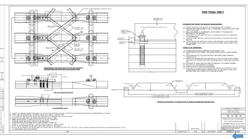
Trial Instructions (for continuation of LWR on curves sharper than 50) 1. LWR/CWR on curves sharper than 50 to be permitted by PCE in consultation with RDSO on case to case basis after ensuring additional measures as above. 2. Slack gauge sleepers to be used and inter-braced as per RDSO trial drg. no. RDSO/T-8329. 3. Sectional AEN shall monitor behaviour of LWR and track condition once in a month. 4. Sr. DEN shall ensure temperature records are maintained, particularly where LWR had been permitted on trial. 5. For trial on gradients steeper than 1 in 100 and those associated with steep curves, these condition shall be ensured except bracing are required in curves sharper than 50.
Track Frame Resistance without Bracing and With Bracing
Buckling Resistance for Temperature Zone –IV @ 60 Cm Sleeper Spacing
FACTOR OF SAFETY AGAINST BUCKLING (With & Without Bracing) Track Structure : 60 Kg Rails & PSC Sleepers at 60 Cm Spacing Longitudinal Ballast Resistance ( Tamped Track) in Kg/m= 1517 Corresponding Frame Resistance (with bracing) (EIQ) in Half Wavelength of Buckling (m)= 5 tm 2= Sectional Area of rail(Cm 2)= Misalignment (in mm)= 76. 86 0. 5 1 2 3 4 5 5. 25 6 7 8 8. 75 2. 15 E+06 α= 1. 15 E-05 15 SN Degree. Radius (m) 1 2 3 4 5 6 7 8 9 10 11 E (in Kg/mm 2)= 667 Tmax-Td 3500. 00 20 1750. 00 20 875. 00 20 583. 33 20 437. 50 20 350. 00 20 333. 33 20 291. 67 20 250. 00 20 218. 75 20 200. 00 20 I FOS 5. 44 5. 39 5. 20 5. 10 5. 00 4. 98 4. 91 4. 81 4. 71 4. 64 Corresponding Frame Resistance (without bracing) (EIQ) in tm 2= Temperature Zone II III FOS(B) Tmax-Td FOS FOS(B) Tmax-Td 6. 77 25 4. 34 5. 41 30 3. 61 4. 50 33 6. 73 25 4. 29 5. 36 30 3. 56 4. 45 33 6. 63 25 4. 19 5. 26 30 3. 46 4. 36 33 6. 53 25 4. 10 5. 17 30 3. 37 4. 26 33 6. 44 25 4. 00 5. 07 30 3. 27 4. 16 33 6. 34 25 3. 91 4. 98 30 3. 17 4. 07 33 6. 32 25 3. 88 4. 95 30 3. 15 4. 04 33 6. 24 25 3. 81 4. 88 30 3. 08 3. 97 33 6. 15 25 3. 71 4. 78 30 2. 98 3. 87 33 6. 05 25 3. 62 4. 69 30 2. 88 3. 78 33 5. 98 25 3. 54 4. 61 30 2. 81 3. 70 33 409 IV FOS 3. 28 3. 23 3. 13 3. 03 2. 94 2. 82 2. 75 2. 65 2. 55 2. 48 FOS(B) 4. 09 4. 04 3. 94 3. 85 3. 75 3. 63 3. 56 3. 46 3. 36 3. 29
Position of Trial • Zonal Railway were asked to conduct trial on laying of LWR on sharp curves and steep gradients vide letter dated 25. 8. 2018. • It is learnt that 7 Zonal Railways have submitted trial report to RDSO in which satisfactory performance of LWR on sharp curves and steep gradients has been reported. • In the report received in RDSO, sharpest degree of curve is 6. 50 • Steepest gradient is 1 in 60.
Conclusion & Recommendations 1. UIC Code 720 R issued in March 2005 does not lay down any restriction on laying of CWR on curves and gradients. It only says that for laying LWR on curves sharper than 300 m radius special measured i. e. fitting anchoring devices to sleepers, are taken. 2. Safety evaluation has been conducted as per safety limit charts for 80 C curve with td=tm+50 C for KK line and 5. 250 C with td=tm+50 C for Central Railways Kasara – Igatpuri and Karjat Lonavala ghats where allowable temperature above stress free temperature has been found as 410 C and 430 C respectively. 3. By considering SFTN (Stress Free temperature Safety factor) conservatively as 100 C, the maximum permissible temperature comes as 660 C and 700 C which is 140 C and 130 C respectively higher than maximum temperature in these sections. 4. Thus laying of LWR on above sections is safe. 5. Safety limit charts provided in UIC 720 R are based on UIC/D 4 loading which has axle load of 22. 5 T and axles with track loading density as 8 T/m which almost similar to CC+8 loading, hence these charts can be used in the absence of detailed analysis by CWERRI program.
Conclusion & Recommedation 6. In Kasara- Igatpuri and Karjat – Lonavala ghats having long and continuous steep gradient of 1 in 37 where banking locomotives are used to haul trains up the grade and trains have to apply brakes continuously to control speed, the laying of LWR on such sections will be critical which will required stringent creep monitoring. 7. It will also be appropriate to provide continuous rail stress monitoring system to monitor locations developing high compressive stresses and also to gains knowledge on trend of stresses. In such a system alarm for rail break and imminent buckling can be provided to alert the Engineers of any potential area and to take prompt action to avert any unsafe operation and to take remedial measure. 8. To prevent rolling down of ballast and to ensure its adequate lateral resistance, ballast walls should be constructed on outside of sharp curves and gap between sleepers and ballast wall completely filled with ballast. 9. Decision to lay LWR/CWR should betaken on the basis of actual temperature records of area where they are to be laid rather than going by temperature map. Td should be judiciously chosen so as to minimize risk of buckling while keeping rail stresses within laid down limits.
Thanks
Trial of LWR on Sharp Curves and Steep Gradients
Angle Frame to increase Track Frame Resistance Measurement of Track Frame Resistance
Rail Stress Monitoring System
Strain Gauge in Rail Web
Rail Stress Monitoring System • It enables real time monitoring of rail stress, providing alerts that helps to prevent rail break and track buckling. Alerts helps in maintenance planning. • Rail Stress Monitoring system enables real-time remote continuous and accurate monitoring of rail stresses, rail stress free temperature and rail temperature. • Rail Stress monitoring system can be installed in known trouble areas for track buckling and rail breakages. • Live data is transmitted efficiently and in real time over 3 G or 4 G networks.