Seismic Design of Concrete Structure Seismic Design of


- Slides: 56
Seismic Design of Concrete Structure
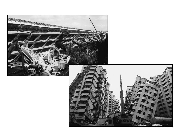
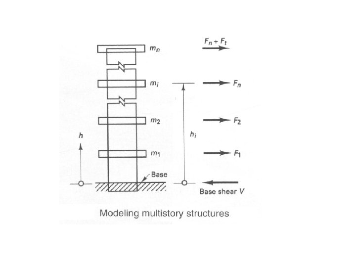
Seismic Design of Concrete Structure • Earthquakes occur in many regions of the world. In certain locations where the intensity of the ground shaking is small, the designer does not have to consider seismic effects. • In other locations-particularly in regions near an active geological fault (a fracture line in the rock structure), such as the San Andreas fault that runs along the western coast of California-large ground motions frequently occur that can damage or destroy buildings and bridges in large areas of cities • Assuming the building is fixed at its base, the displacement of floors will vary from zero at the base to a maximum at the roof
Earthquake focus and epicenter
Distribution of magnitude 5 or greater earthquakes, 1980 - 1990
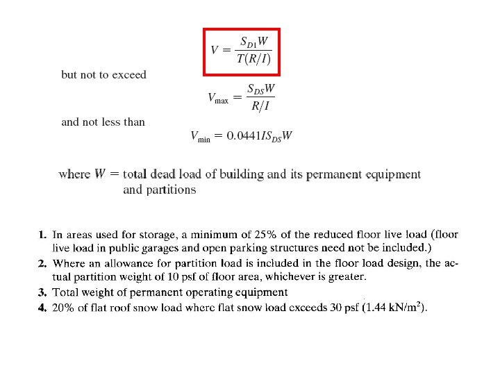
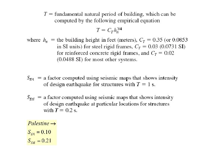
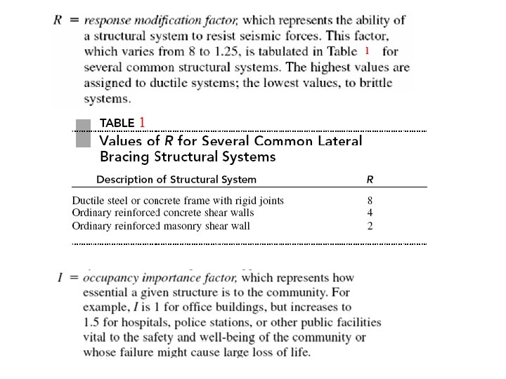
There are several analytical procedures to determine the magnitude of the base shear for which buildings must be designed, we will only consider the equivalent lateral force procedure, described in the ANSI/ASCE and UBC standard. Using this procedure, we compute the magnitude of the base shear as
Table 2: Design Coefficients & Factors for Basic Seismic-Force-Resisting Systems
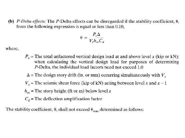
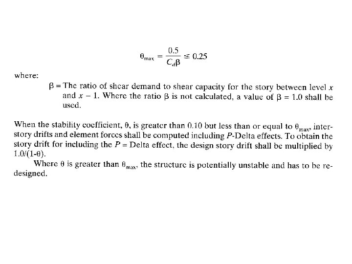
Story Drift & The P-Delta Effect
Allowable Story Drift, D
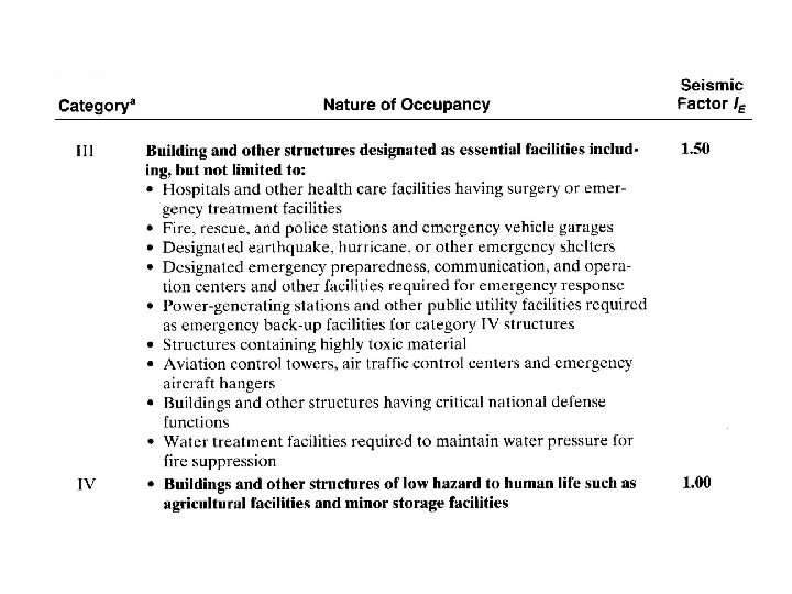
Important Factor
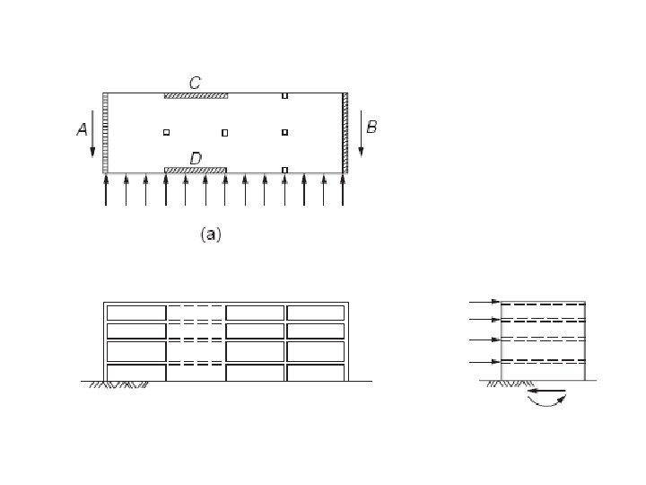
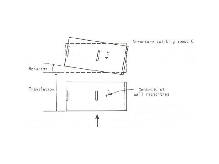
Overturning
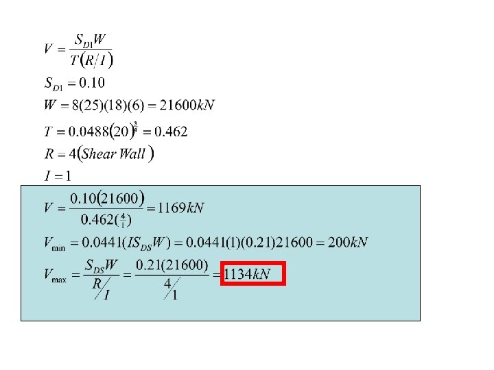
Example 1 • Determine the design seismic forces acting at each floor of the six -story office building in Figure below. • D. L=8 k. N/m 2 • L. L=2. 5 k. N/m 2 • Shear wall system N 25 m 18 m
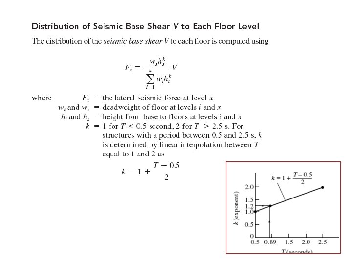
T=0. 462 < 0. 5 then k=1
Note: Column 4 = column 3 a * Column 2 (Fx = column 5 * (V = 1134)) Vx = cumulative column 6 Mx = moment from Fx can calculated from shear Area
Shear Wall Design
Introduction Shear walls provide a high in-plane stiffness and strength for both lateral and gravity loads, and are ideally suitable for tall buildings, especially those conceived in reinforced concrete. Tall buildings designed to carry the entire lateral loading through shear walls can be economical to heights of around 40 stories. Taller structures should combine shear walls with other structural systems.
Shear Wall design
Shear Wall Design Steps 1 - Calculate External Load 2 - boundary element check if Then boundary elements are not required
Then choose the one of:
3 - Longitudinal Reinforcement At least two curtains of reinforcement are needed in the wall if the in-plane factored shear exceed a value of
Minimum reinforcement
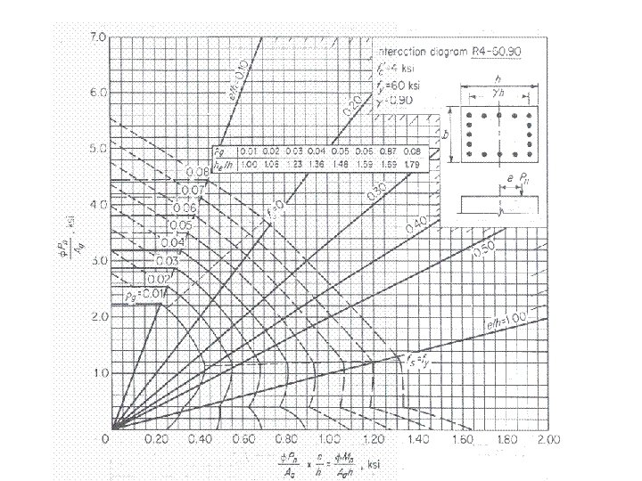
4 - Verify adequacy of shear wall section at its base under combined axial load and bending moment
5 - Boundary element transverse reinforcement You must check it in two dimension
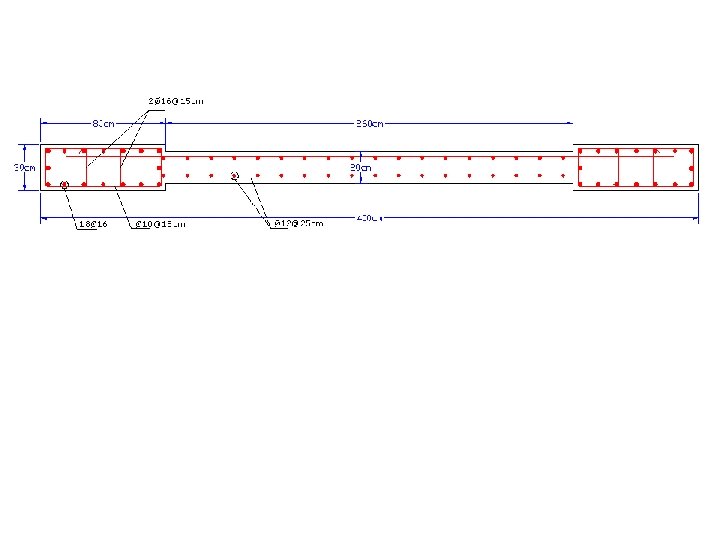
Example 1 Design the following shear wall 1 - Calculate External Load Moment Shear Force
2 - boundary element check
3 - Longitudinal Reinforcement At least two curtains of reinforcement are needed in the wall if the in-plane factored shear exceed a value of Minimum reinforcement
4 - Verify adequacy of shear wall section at its base under combined axial load and bending moment
5 - Boundary element transverse reinforcement Check short direction Check long direction
Check long direction in short direction use 2 legs close hoop & 2 internal legs
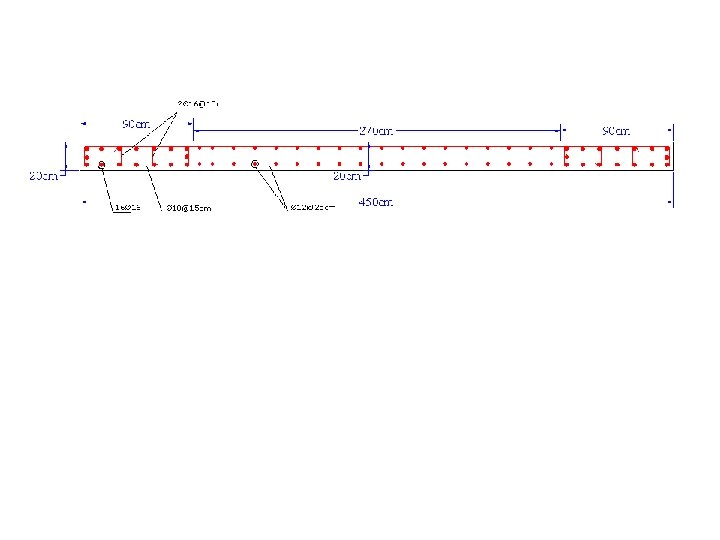
Design Example Design Shear wall 1 & 2 in the figure below Gaza City D. L=8 k. N/m 2 L. L=2. 5 k. N/m 2
1 - calculate the length of shear wall 1 y x
2 - Seismic Shear for the total building
For the total Building T=0. 55> 0. 5
V = 909 k. N M =16726 k. N. m y For shear walls x
In this example without neglect the effect of twist force 2 For shear wall No. 1 1
3 - In this example we will neglect the effect of twist force 2 For shear wall No. 1 For shear wall No. 2 1
4 - Shear wall design boundary element check
Longitudinal Reinforcement At least two curtains of reinforcement are needed in the wall if the in-plane factored shear exceed a value of Minimum reinforcement
Verify adequacy of shear wall section at its base under combined axial load and bending moment
Boundary element transverse reinforcement Check short direction Check long direction
Check long direction in short direction use 2 legs close hoop & 2 internal legs in short direction use 2 legs close hoop Repeat the last procedure for Shear wall 2