Sci Fi Installation and Commissioning U Uwer May17

- Slides: 29
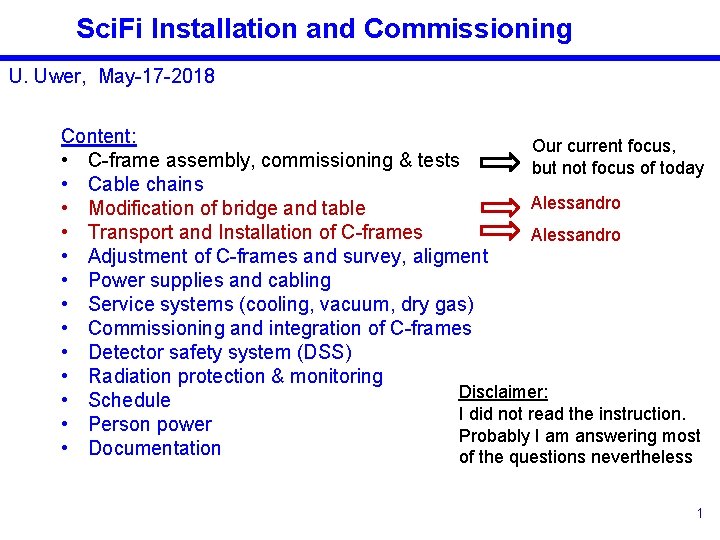
Sci. Fi Installation and Commissioning U. Uwer, May-17 -2018 Content: Our current focus, • C-frame assembly, commissioning & tests but not focus of today • Cable chains Alessandro • Modification of bridge and table • Transport and Installation of C-frames Alessandro • Adjustment of C-frames and survey, aligment • Power supplies and cabling • Service systems (cooling, vacuum, dry gas) • Commissioning and integration of C-frames • Detector safety system (DSS) • Radiation protection & monitoring Disclaimer: • Schedule I did not read the instruction. • Person power Probably I am answering most • Documentation of the questions nevertheless 1
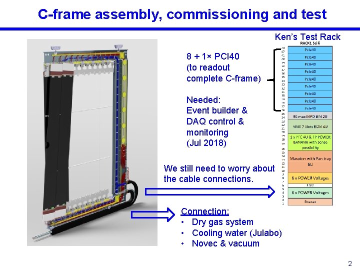
C-frame assembly, commissioning and test Ken’s Test Rack 8 + 1× PCI 40 (to readout complete C-frame) Needed: Event builder & DAQ control & monitoring (Jul 2018) We still need to worry about the cable connections. Connection: • Dry gas system • Cooling water (Julabo) • Novec & vacuum 2
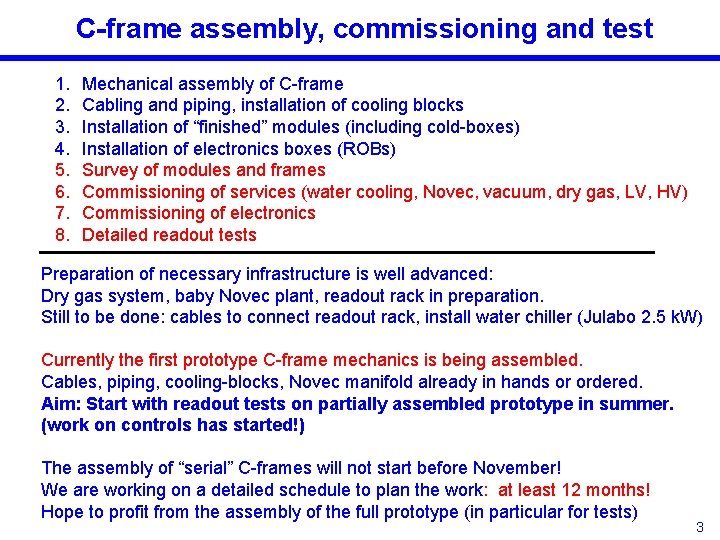
C-frame assembly, commissioning and test 1. 2. 3. 4. 5. 6. 7. 8. Mechanical assembly of C-frame Cabling and piping, installation of cooling blocks Installation of “finished” modules (including cold-boxes) Installation of electronics boxes (ROBs) Survey of modules and frames Commissioning of services (water cooling, Novec, vacuum, dry gas, LV, HV) Commissioning of electronics Detailed readout tests Preparation of necessary infrastructure is well advanced: Dry gas system, baby Novec plant, readout rack in preparation. Still to be done: cables to connect readout rack, install water chiller (Julabo 2. 5 k. W) Currently the first prototype C-frame mechanics is being assembled. Cables, piping, cooling-blocks, Novec manifold already in hands or ordered. Aim: Start with readout tests on partially assembled prototype in summer. (work on controls has started!) The assembly of “serial” C-frames will not start before November! We are working on a detailed schedule to plan the work: at least 12 months! Hope to profit from the assembly of the full prototype (in particular for tests) 3
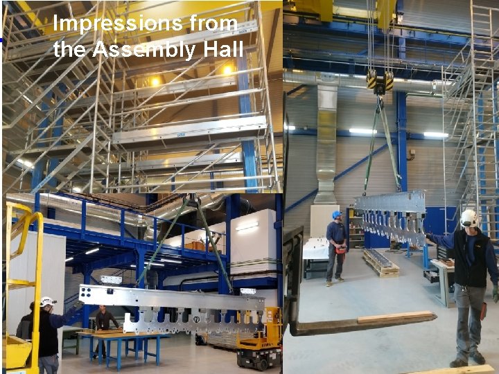
Impressions from the Assembly Hall 4
Cable Chains On-going design work: 2 rolling-ducts per C-frame: 1. cables and fibres 2. vacuum insulated Novec lines, water cooling, dry gas. W/r to older study the diameter of the Novec lines has increased. OT cable ducts are not sufficient anymore. Probably need to increase the cross section of at least one cable duct (larger width). Need to study fitting in the envelope! 5
Modifications & Installation Alessandro’s presentation: • Modifications of bridge • Transport of C-frames • Installation of C-frame • Handling tools 6
Adjustment of C-frames, survey and alignment Mechanical adjustment: Stop-and-approach system for the movement of the C-frames over the last few centimeters. Designed by Augusto/Tomsk? : stopper plus an electronic proximity indicator. A clutch mounted on the approaching system driving shaft will be used to guarantee that no significant force can be applied after that the mechanical stopper will be reached. Survey: We plan to survey all 12 frames after the assembly in the assembly hall (survey point on the modules). Once the C-frames are installed the full planes (A and C-side together) will be survey once more. Alignment monitoring system: A monitoring of the movement of the half-planes using BCAM or alternatively Rasnik is being discussed. Requirements need to be defined. 7
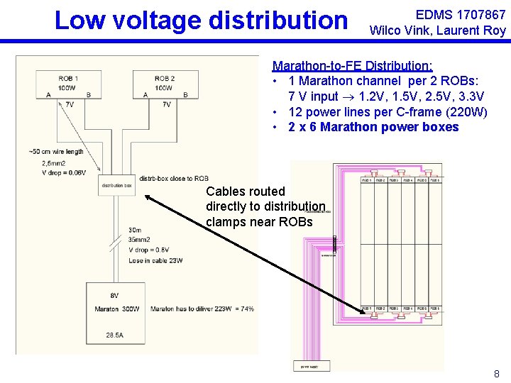
Low voltage distribution EDMS 1707867 Wilco Vink, Laurent Roy Marathon-to-FE Distribution: • 1 Marathon channel per 2 ROBs: 7 V input 1. 2 V, 1. 5 V, 2. 5 V, 3. 3 V • 12 power lines per C-frame (220 W) • 2 x 6 Marathon power boxes Cables routed directly to distribution clamps near ROBs 8
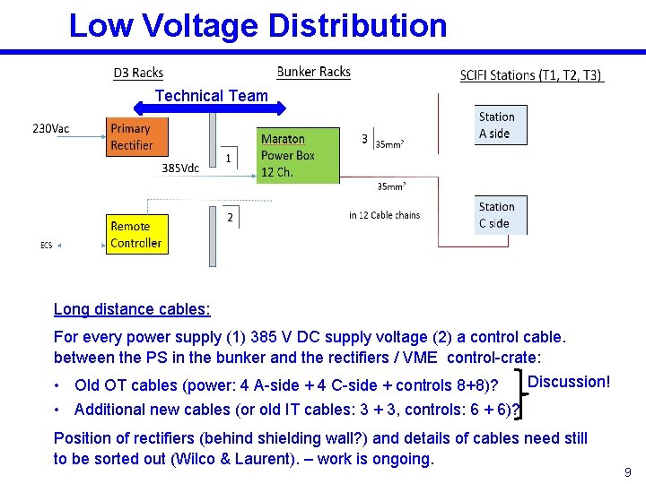
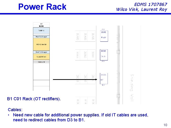
Low Voltage Distribution Technical Team Long distance cables: For every power supply (1) 385 V DC supply voltage (2) a control cable. between the PS in the bunker and the rectifiers / VME control-crate: Discussion! • Old OT cables (power: 4 A-side + 4 C-side + controls 8+8)? • Additional new cables (or old IT cables: 3 + 3, controls: 6 + 6)? Position of rectifiers (behind shielding wall? ) and details of cables need still to be sorted out (Wilco & Laurent). – work is ongoing. 9
Power Rack EDMS 1707867 Wilco Vink, Laurent Roy B 1 C 01 Rack (OT rectifiers). Cables: • Need new cable for additional power supplies. If old IT cables are used, need to redirect cables from D 3 to B 1. 10
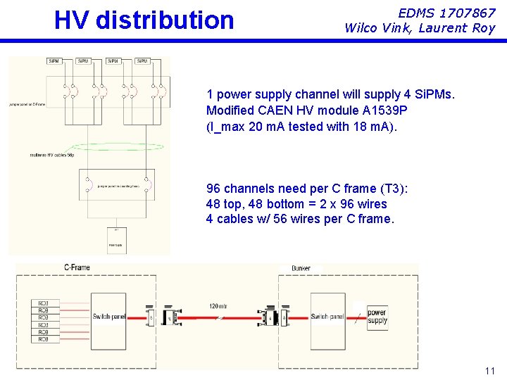
HV distribution EDMS 1707867 Wilco Vink, Laurent Roy 1 power supply channel will supply 4 Si. PMs. Modified CAEN HV module A 1539 P (I_max 20 m. A tested with 18 m. A). 96 channels need per C frame (T 3): 48 top, 48 bottom = 2 x 96 wires 4 cables w/ 56 wires per C frame. 11
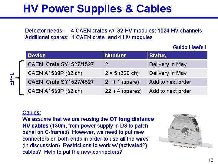
HV Power Supplies & Cables Detector needs: 4 CAEN crates w/ 32 HV modules: 1024 HV channels Additional spares: 1 CAEN crate and 4 HV modules EPFL Guido Haefeli Device Number Status CAEN Crate SY 1527/4527 2 Delivery in May CAEN A 1539 P (32 ch) 2 × 5 (320 ch) Delivery in May CAEN Crate SY 1527/4527 2 + 1 (spare) Add to next order CAEN A 1539 P (32 ch) 22 + 4 (spares) Add to next order Cables: We assume that we are reusing the OT long distance HV cables (130 m, from power supply in D 3 to patch panel on C-frames). However, we need to put new connectors on both ends in order to use all the wires (in discusssion). Restrictions to work w/ (activated? ) cables? Help to put the new connectors? 12
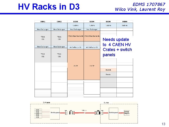
HV Racks in D 3 EDMS 1707867 Wilco Vink, Laurent Roy Needs update to 4 CAEN HV Crates + switch panels 13
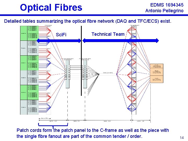
Optical Fibres EDMS 1694345 Antonio Pellegrino Detailed tables summarizing the optical fibre network (DAQ and TFC/ECS) exist. Sci. Fi Technical Team Patch cords form the patch panel to the C-frame as well as the piece with the single fibre fanout are part of the common tender / order. 14
Other control/monitoring cables • • • Control cables for dry gas flushing Control cables for vacuum Control cables for Novec distribution? Cables for alignment system (BCAM/Rasnik) … What else? Need more work! 15
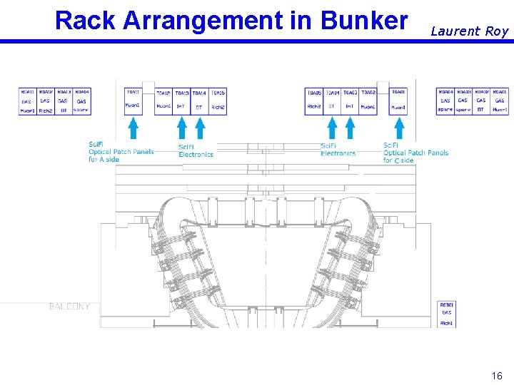
Rack Arrangement in Bunker Laurent Roy 16
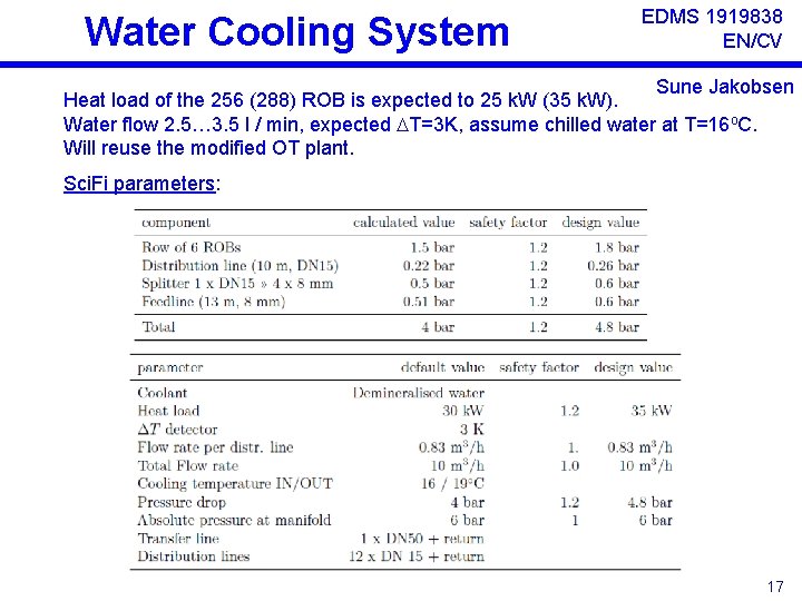
Water Cooling System EDMS 1919838 EN/CV Sune Jakobsen Heat load of the 256 (288) ROB is expected to 25 k. W (35 k. W). Water flow 2. 5… 3. 5 l / min, expected T=3 K, assume chilled water at T=16 o. C. Will reuse the modified OT plant. Sci. Fi parameters: 17
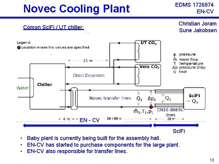
Novec Cooling Plant Comon Sci. Fi / UT chiller: EDMS 1726874 EN-CV Christian Joram Sune Jakobsen EN - CV Sci. Fi • Baby plant is currently being built for the assembly hall. • EN-CV has started to purchase components for the large plant. • EN-CV also responsible for transfer lines. 18
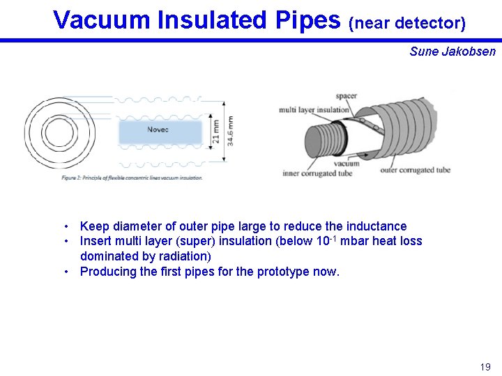
Vacuum Insulated Pipes (near detector) Sune Jakobsen • Keep diameter of outer pipe large to reduce the inductance • Insert multi layer (super) insulation (below 10 -1 mbar heat loss dominated by radiation) • Producing the first pipes for the prototype now. 19
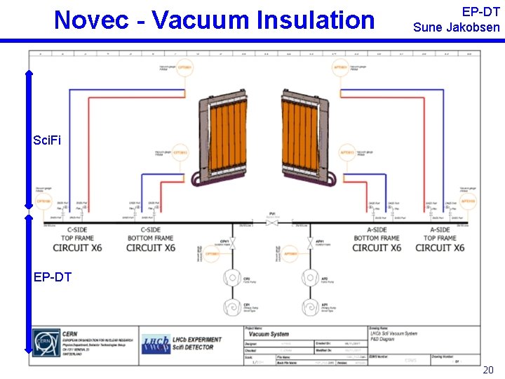
Novec - Vacuum Insulation EP-DT Sune Jakobsen Sci. Fi EP-DT 20
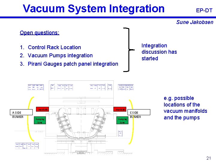
Vacuum System Integration EP-DT Sune Jakobsen Open questions: Integration discussion has started 1. Control Rack Location 2. Vacuum Pumps integration 3. Pirani Gauges patch panel integration A SIDE BUNKER Manifolds Pumping Zone C SIDE BUNKER e. g. possible locations of the vacuum manifolds and the pumps 21
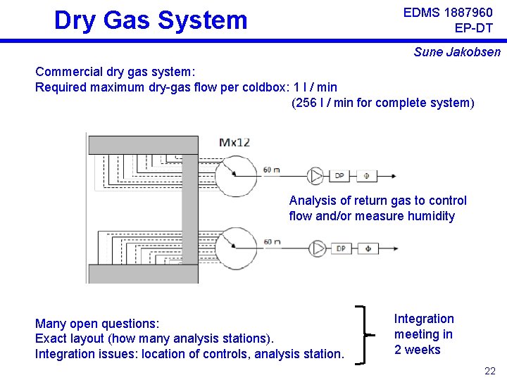
EDMS 1887960 EP-DT Dry Gas System Sune Jakobsen Commercial dry gas system: Required maximum dry-gas flow per coldbox: 1 l / min (256 l / min for complete system) Analysis of return gas to control flow and/or measure humidity Many open questions: Exact layout (how many analysis stations). Integration issues: location of controls, analysis station. Integration meeting in 2 weeks 22
Commissioning & Integration We will build on the experience we will gather in the near future: a detailed test and commissioning program including the operation of the services and intense DAQ tests will be developed with the currently built prototype C-frame. The commissioning and test program will then be applied to the 12 serial frames. The in-situ tests will, to a large extend, repeat the commissioning sequence of the assembly hall. Additional work is needed to include the C-frame into the general LHCb control and DAQ framework. However, we hope that this work will be rather limited as many Win. CC interfaces have to be developed already for the assembly. 23
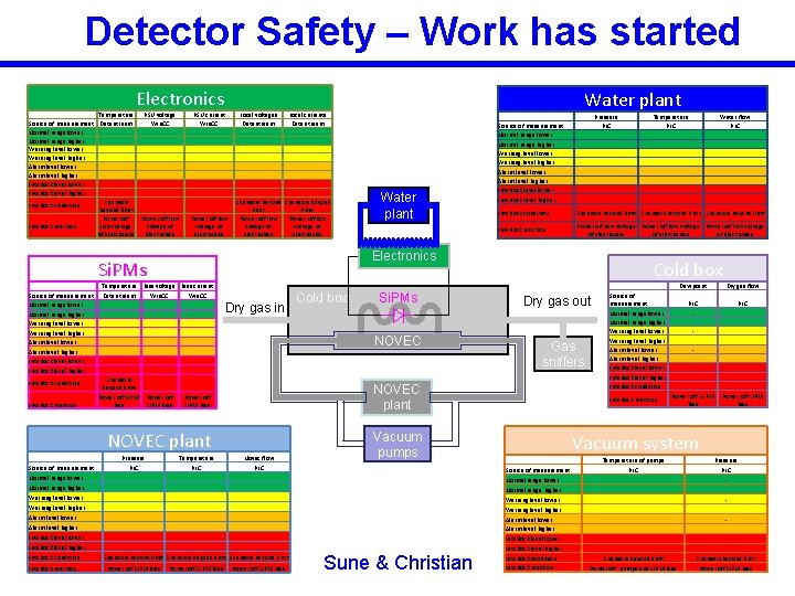
Detector Safety – Work has started Electronics Temperature Source of measurement Data stream Normal range lower Normal range higher Warning level lower Warning level higher Alarm level lower Alarm level higher Interlock level lower Interlock level higher 2 sensors Interlock condition beyond limit Power off Interlock reaction low voltage of electronics PSU voltage Win. CC PSU current Win. CC Power off low voltage of electronics Local voltages Data stream 2 sensors beyond limit Power off low voltage of electronics Interlock condition Interlock reaction Temperature Bias voltage Bias current Data stream Win. CC 2 sensors beyond limit Power off Si. PM Power off bias Si. PM bias Dry gas in Temperature Novac flow PLC PLC Normal range lower Normal range higher Warning level lower Warning level higher Alarm level lower Alarm level higher Interlock level lower Interlock level higher Interlock condition Interlock reaction 2 sensors beyond limit Power off Si. PM bias Pressure PLC Power off Si. PM bias Si. PMs Power off Si. PM bias Vacuum pumps Sune & Christian Temperature PLC Water flow PLC Interlock condition 2 sensors beyond limit Interlock reaction Power off low voltage of electronics Cold box Dry gas out Gas sniffers NOVEC plant Pressure Source of measurement Cold box NOVEC plant Water plant Source of measurement Normal range lower Normal range higher Warning level lower Warning level higher Alarm level lower Alarm level higher Interlock level lower Interlock level higher Electronics Si. PMs Source of measurement Normal range lower Normal range higher Warning level lower Warning level higher Alarm level lower Alarm level higher Interlock level lower Interlock level higher Water plant Local currents Data stream Source of measurement Normal range lower Normal range higher Warning level lower Warning level higher Alarm level lower Alarm level higher Interlock level lower Interlock level higher Interlock condition Interlock reaction Dew point Dry gas flow PLC Power off Si. PM bias Vacuum system Source of measurement Normal range lower Normal range higher Warning level lower Warning level higher Alarm level lower Alarm level higher Interlock level lower Interlock level higher Interlock condition Interlock reaction Temperature of pumps PLC 2 sensors beyond limit Pressure PLC 2 sensors beyond limit Power off pumps and Si. PM bias Power off Si. PM bias
Radiation Protection & Monitoring • Work with parts of the old detector (e. g. modification of bridge, modification of old cables): What are the requirements? • The Sci. Fi production database follows the labeling scheme required by the radiation protection / tracability database. All installed items will carry corresponding labels. • Sune started to work on passive radiation monitoring of modules and of Si. PMs/electronics. Sensor type defined – foresee only positioning. 25
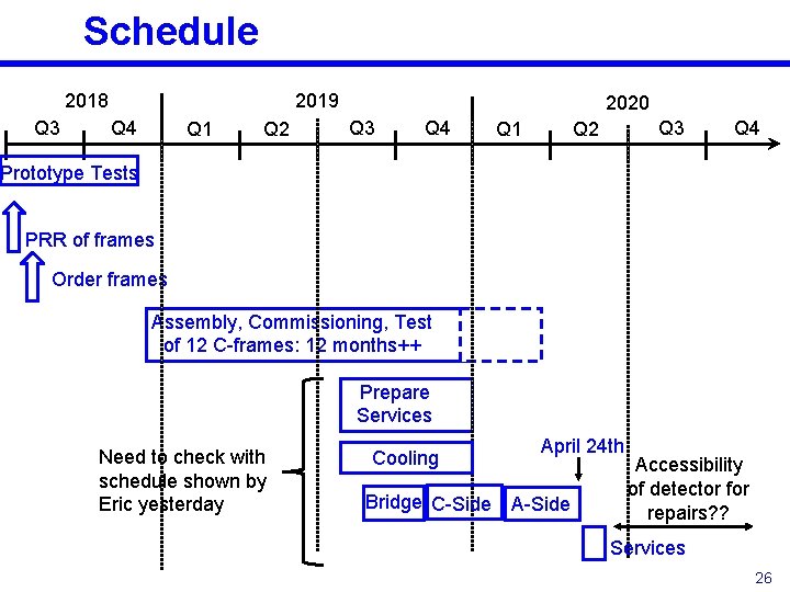
Schedule 2018 Q 3 2019 Q 4 Q 1 Q 2 2020 Q 3 Q 4 Q 1 Q 3 Q 2 Q 4 Prototype Tests PRR of frames Order frames Assembly, Commissioning, Test of 12 C-frames: 12 months++ Prepare Services Need to check with schedule shown by Eric yesterday Cooling Bridge C-Side April 24 th A-Side Accessibility of detector for repairs? ? Services 26
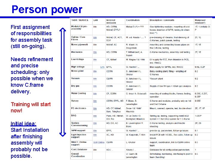
Person power First assignment of responsibilities for assembly task (still on-going). Needs refinement and precise scheduling: only possible when we know C. frame delivery. Training will start now! Initial idea: Start Installation after finishing assembly will probably not be possible. 27
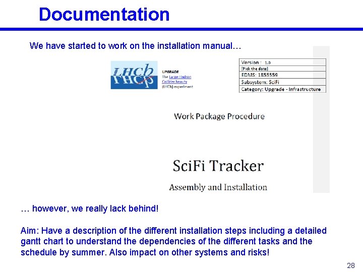
Documentation We have started to work on the installation manual… … however, we really lack behind! Aim: Have a description of the different installation steps including a detailed gantt chart to understand the dependencies of the different tasks and the schedule by summer. Also impact on other systems and risks! 28
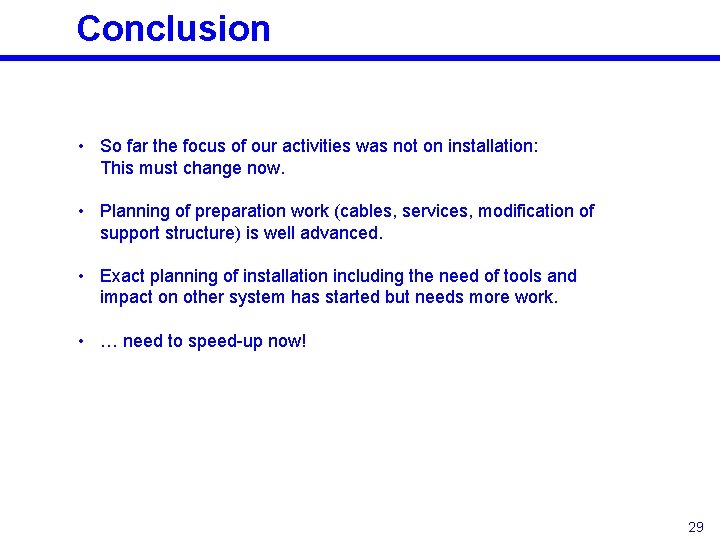
Conclusion • So far the focus of our activities was not on installation: This must change now. • Planning of preparation work (cables, services, modification of support structure) is well advanced. • Exact planning of installation including the need of tools and impact on other system has started but needs more work. • … need to speed-up now! 29