PRDS Commissioning and Acceptance Procedure Dominik Sikora Preliminary
- Slides: 8
PRDS Commissioning and Acceptance Procedure Dominik Sikora Preliminary Design Review 15. 03. 2017, Lund
Phase Drifts Verification Issue • Power levels and phase noise are easy to measure • Direct phase drift measurements are not possible – measuring equipment has to be much better than PRL performance – PRL is very long, measuring cables influence • Final phase drifts must be estimated indirectly basing on laboratory characterization 15. 03. 2017, Lund PRDS Commissioning and Acceptance Procedure, D. Sikora 2
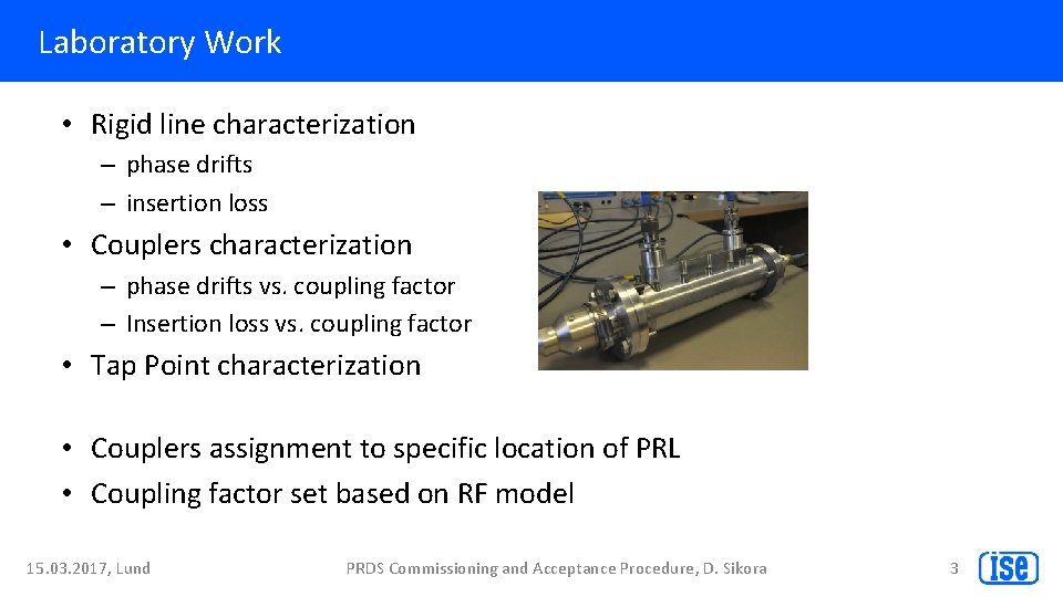
Laboratory Work • Rigid line characterization – phase drifts – insertion loss • Couplers characterization – phase drifts vs. coupling factor – Insertion loss vs. coupling factor • Tap Point characterization • Couplers assignment to specific location of PRL • Coupling factor set based on RF model 15. 03. 2017, Lund PRDS Commissioning and Acceptance Procedure, D. Sikora 3
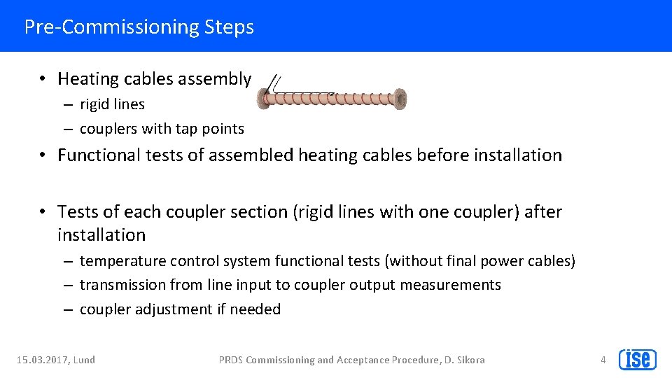
Pre-Commissioning Steps • Heating cables assembly – rigid lines – couplers with tap points • Functional tests of assembled heating cables before installation • Tests of each coupler section (rigid lines with one coupler) after installation – temperature control system functional tests (without final power cables) – transmission from line input to coupler output measurements – coupler adjustment if needed 15. 03. 2017, Lund PRDS Commissioning and Acceptance Procedure, D. Sikora 4
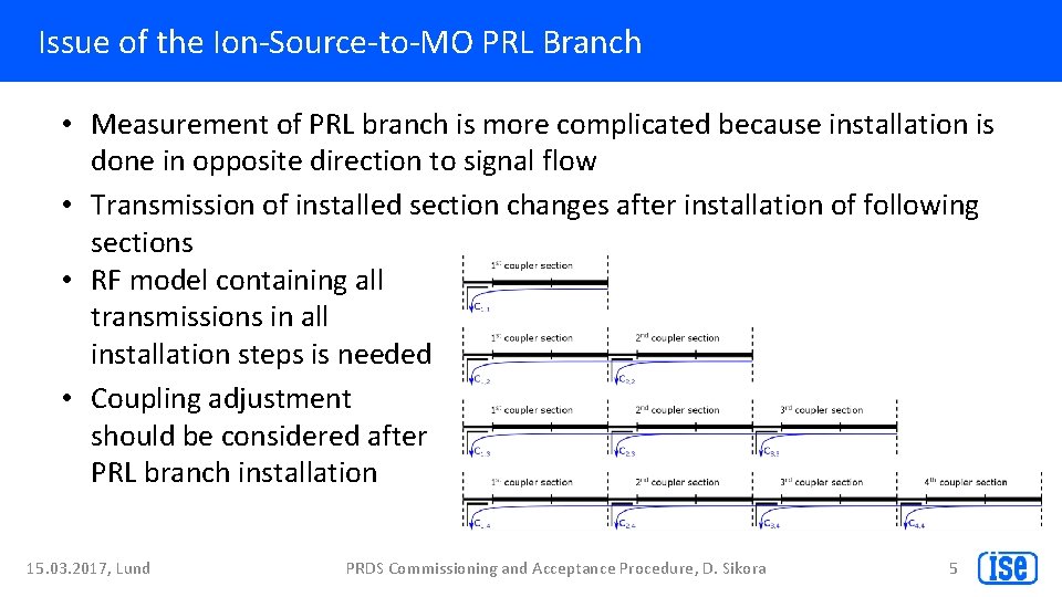
Issue of the Ion-Source-to-MO PRL Branch • Measurement of PRL branch is more complicated because installation is done in opposite direction to signal flow • Transmission of installed section changes after installation of following sections • RF model containing all transmissions in all installation steps is needed • Coupling adjustment should be considered after PRL branch installation 15. 03. 2017, Lund PRDS Commissioning and Acceptance Procedure, D. Sikora 5
Commissioning Steps • MO amplifier stage commissioning – output power levels measurements – diagnostics verification • Temperature control system pre-commissioning – PRL warm up – functional tests with final power cables and Beckhof modules – temperature stabilization with final set-point • Pressure and humidity control system commissioning – filling slowly the rigid line with nitrogen and checking if PRL is leakages free – diagnostics checking • Temperature control system commissioning – Long term temperature tests during significant environment temperature changes 15. 03. 2017, Lund PRDS Commissioning and Acceptance Procedure, D. Sikora 6
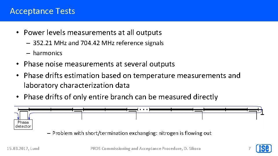
Acceptance Tests • Power levels measurements at all outputs – 352. 21 MHz and 704. 42 MHz reference signals – harmonics • Phase noise measurements at several outputs • Phase drifts estimation based on temperature measurements and laboratory characterization data • Phase drifts of only entire branch can be measured directly – Problem with short/termination exchanging: nitrogen is flowing out 15. 03. 2017, Lund PRDS Commissioning and Acceptance Procedure, D. Sikora 7
Thank you. 15. 03. 2017, Lund PRDS Commissioning and Acceptance Procedure, D. Sikora 8