Satellite Communications Firoz Ahmed Siddiqui Earth Station Design


, Broadcast")


 l l l Travelling Wave Tube Amplifier (TWTA) is the")


 l l A Low Noise Amplifier (LNA) is an electronic")
 l l l There are two low noise amplifiers possible:")


 is a technique by which the total bandwidth")


 is a method of transmitting and receiving independent signals")

 is a system that allows multiple users to")
- Slides: 37
Satellite Communications Firoz Ahmed Siddiqui
Earth Station Design l l l The earth station is the vital element in any satellite communication network. Even though the design of the earth station is comparatively easy as compare to design of satellite, but it is very tough to maintain communication throughout its life time without any interruption. The design of the earth station should be most cost effective and reliable while retaining the desired signal quality.
l l l The earth station can be only receiving or both transmitting and receiving types. Among many earth stations one of the earth station is designated as master control earth station, which controls the operation of satellite remotely from ground. In other words, attitude and orbit control, and telemetry, tracking and control of the satellite is performed by this earth station.
l l The earth station can be categorized as Fixed Satellite Service (FSS), Broadcast Satellite Service (BSS) and Mobile Satellite Service (MSS). An earth station basically consists of two parts. The first part is the RF terminal, which consists of baseband equipment, an encoder and decoder and a modulator and demodulator.
l l l The RF terminal is located as near as possible to the antenna so as to avoid the losses and attenuation of the RF signal in the transmission lines connecting the antenna and the RF equipment. The baseband equipment can be located at convenient location away from the RF terminal. The fundamental parameter in describing the earth station is the figure of merit, the G/T ratio.
l l l Figure of merit represents the sensitivity of an earth station. A higher value implies a more sensitive earth station. The value of G/T ratio ranges from 12 – 14 d. B/K for very small to large FSS earth stations. It ranges between -24 and -4 d. B/K for small to large MSS earth stations and the range is between 8 and 15 for small to large BSS earth stations.
l The design of earth station depends on various factors such as type of service – FSS of BSS or MSS, types of communication – voice, data, television etc. , traffic requirements – number of channels, continuous or bursty, quality of the signal, cost and reliability.
l l The design of earth station has two stages. At the first stage, the parameter of the earth station like the transmitted power, EIRP, G/T ratio, type of modulation, type of access etc. , are determined by the designer for a given application. In the second stage of the design, the engineer gives the layout, cost effectiveness etc. , to implement the design proposed by the designer.
High Power Amplifier (HPA) l l l Travelling Wave Tube Amplifier (TWTA) is the widely used high power amplifier in the earth stations. This employs the principle of velocity modulation in the form of travelling waves. The RF signal to be amplified travels down a periodic structure called helix. Electrons emitted from the cathode of the tube are focused into a beam along the axis of the helix and removed at the end of the tube after delivering their energy to RF field.
l l l The helix slows down the velocity of the RF signal to that of electron beam for a continuous interaction of electrons and the RF signal field, which results in transfer of energy from electrons to the RF signal. The amplification of the signal grows as the beam travels down the tube. It can achieve 10% bandwidth, which is sufficient for operation of many transponders of the satellite.
l l Klystron amplifier can also be used as high power amplifier in earth station since it has higher gain and more efficiency. But the drawback of Klystron amplifier is the smaller bandwidth of the order of 2%.
Travelling wave tube amplifier
Low Noise Amplifier (LNA) l l A Low Noise Amplifier (LNA) is an electronic amplifier that amplifies a very low power signal without significantly degrading its signal to noise ratio. An amplifier increases the power of both the signal and noise present at its input.
Low Noise Amplifier (LNA) l l l There are two low noise amplifiers possible: parametric amplifier and Ga. As FET amplifier. The parametric amplifier has a very low noise characteristic and is widely used in old days. But these days, Ga. As FET amplifier finds wide application because of its stability, reliability, low cost and very low noise temperature.
l l The performance of this amplifier can further be improved in terms of noise figure when the amplifier is cooled. Thermoelectric coolers are generally employed to cool such amplifiers. With cooling upto 223 K, they can operate satisfactorily upto 12. 2 GHz with a noise temperature of 150 K.
l
l l A circulator is employed to route the input signal to be amplified at port 1 to the resonant circuit at port 2 and to transfer the reflected amplified signal from the resonant circuits from port 2 to port 3. Since the amplifier exhibits negative resistance characteristic, it can amplify the input signal.
l
Parametric low noise amplifier
l For a Ga. As FET amplifier, the typical front – end stage is shown in figure below Ga. As FET amplifier
Tracking System l l Tracking of the satellite is required when the satellite drifts out of the earth station’s antenna beam width significantly. The antennas with large beam width do not require satellite tracking. A tracking system is required to perform satellite acquisition and tracking. The tracking of the satellite can be automatic, manual or programmed or any combination of all these three.
l l l Automatic tracking systems are closed loop control systems and are highly accurate. Manual tracking system is generally employed with all the earth stations so to have tracking even when other tracking systems fail and to have uninterrupted communication between the earth station and satellite. In programe tracking, the antenna is driven to the predicted position by a computer.
Satellite Tracking System
l l l Figure shows the main functional block diagram of a satellite tracking system. Communication satellite transmits a guiding signal, which is used by the earth station for tracking. This received signal is fed in to auto track receiver where tracking corrections are derived. The feed system provides the required error signals.
l l The output is processed and used to drive each axis of the antenna to the estimated satellite position. There are various auto track systems employed. Some of them are conical scan, monopulse, step pulse etc.
l l In conical scan, an antenna beam is switched between the two positions. When an approaching target is at the center of these beams, the echoes from each beam are equal in magnitude but in other positions they are unequal. The antenna position is adjusted that the two echoes become equal in magnitude. A constant signal indicates that the satellite is on the axis, where as a rise or fall per revolution shows a pointing error.
l l In monopulse technique, the errors for driving the antenna system are derived by simultaneous lobing of the received signals. Amplitude comparison or phase comparison or comparison of both amplitude and phase types of monopulse tracking are possible.
l l In the step tracking technique, error signals are derived from amplitude sensing. The operation is based on maximization of received signal by moving the axes in small steps until maximization is effected. In this technique the antenna is moved about in a pre-determined fashion, and the signal amplitude is noted. Maximum signal indicates the best beam position.
l From the knowledge of main beam shape, the true direction of the satellite is estimated and the antenna is then pointed in that direction.
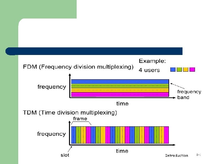
Multiplexing l l RF channel multiplexing is a process that divides a single radio transmission path into several parts that can transfer multiple communication (voice and/or data) channels. Multiplexing may be frequency division (dividing into frequency bands), time division (dividing into time slots), code division (dividing into coded data that randomly overlap), or statistical multiplexing (dynamically assigning portions of channels when activity exists)
FDM l l Frequency-Division Multiplexing (FDM) is a technique by which the total bandwidth available in a communication medium is divided into a series of non-overlapping frequency bands, each of which is used to carry a separate signal. This allows a single transmission medium such as a cable or optical fiber to be shared by multiple independent signals.
FDM l l The most natural example of frequency-division multiplexing is radio and television broadcasting, in which multiple radio signals at different frequencies pass through the air at the same time. Another example is cable television, in which many television channels are carried simultaneously on a single cable.
FDM l FDM is also used by telephone systems to transmit multiple telephone calls through high capacity trunk lines, communications satellites to transmit multiple channels of data on uplink and downlink radio beams.
TDM l Time-division multiplexing (TDM) is a method of transmitting and receiving independent signals over a common signal path by means of synchronized switches at each end of the transmission line so that each signal appears on the line only a fraction of time in an alternating pattern.
TDM l l l The time domain is divided into several recurrent time slots of fixed length, one for each sub-channel. A sample byte or data block of sub-channel 1 is transmitted during time slot 1, sub-channel 2 during time slot 2, etc. One TDM frame consists of one time slot per sub-channel plus a synchronization channel and sometimes error correction channel before the synchronization.
CDM l Code division multiplexing (CDM) is a system that allows multiple users to share one or more radio channels for service by adding unique codes to each data signal that is being sent to and from each of the radio transceivers. These codes are used to spread the data signal to a bandwidth much wider than is necessary to transmit the data signal without the code.