PROF MRS NAJMA SIDDIQUI ANJUMAN COLLEGE OF ENGINEERING


- Slides: 14
PROF. MRS NAJMA SIDDIQUI ANJUMAN COLLEGE OF ENGINEERING & TECHNOLOGY Department of Electrical Engineering SUB: - Basic Electrical Engineering
UNIT I : SINGLE PHASE TRANSFORMERS Ø Ø Ø Objectives: To understand. Principle of operation of Single phase transformer, Construction and types of Single phase transformer, Concept of ideal transformer, Operation at no load, Operation on load, Losses in transformer, Open circuit test to determine core losses, Short circuit test to determine copper losses, Performance indices i. e. Efficiency and Voltage regulation, Concept of maximum efficiency, condition for maximum efficiency, Concept of Autotransformer, construction, k. VA rating & saving of copper, Applications
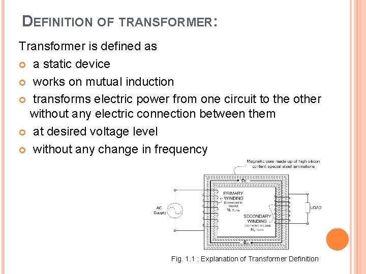
DEFINITION OF TRANSFORMER: Transformer is defined as a static device works on mutual induction transforms electric power from one circuit to the other without any electric connection between them at desired voltage level without any change in frequency Fig. 1. 1 : Explanation of Transformer Definition
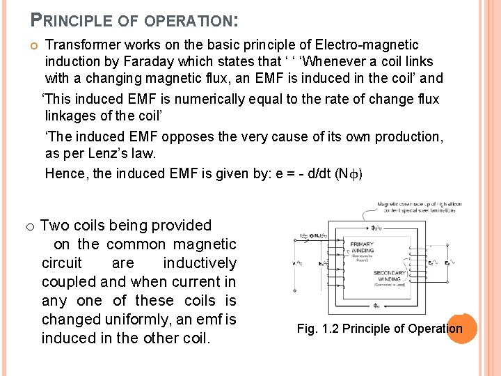
PRINCIPLE OF OPERATION: Transformer works on the basic principle of Electro-magnetic induction by Faraday which states that ‘ ‘ ‘Whenever a coil links with a changing magnetic flux, an EMF is induced in the coil’ and ‘This induced EMF is numerically equal to the rate of change flux linkages of the coil’ ‘The induced EMF opposes the very cause of its own production, as per Lenz’s law. Hence, the induced EMF is given by: e = - d/dt (Nφ) o Two coils being provided on the common magnetic circuit are inductively coupled and when current in any one of these coils is changed uniformly, an emf is induced in the other coil. Fig. 1. 2 Principle of Operation
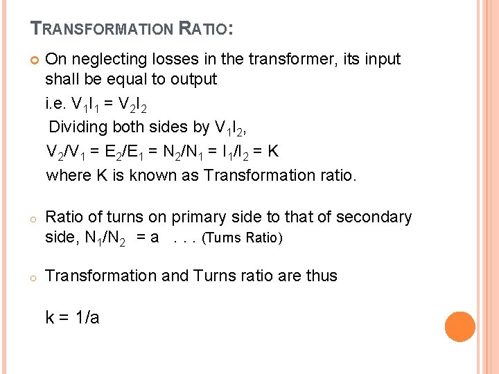
TRANSFORMATION RATIO: On neglecting losses in the transformer, its input shall be equal to output i. e. V 1 I 1 = V 2 I 2 Dividing both sides by V 1 I 2, V 2/V 1 = E 2/E 1 = N 2/N 1 = I 1/I 2 = K where K is known as Transformation ratio. o Ratio of turns on primary side to that of secondary side, N 1/N 2 = a. . . (Turns Ratio) o Transformation and Turns ratio are thus k = 1/a
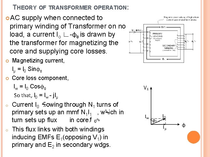
THEORY OF TRANSFORMER OPERATION: AC supply when connected to primary winding of Transformer on no load, a current Io ∟-φ0 is drawn by the transformer for magnetizing the core and supplying core losses. Magnetizing current, Iµ = I 0 Sinφ0 Core loss component, Iw = I 0 Cosφ0 So that, I 0 = Iw - j. Iµ o Current I 0 flowing through N 1 turns of primary sets up an mmf N 1 I 1 , which in turn sets up flux in core. This flux links with both windings inducing EMFs E 1(opposing V 1) in primary and E 2 in secondary wdgs. o
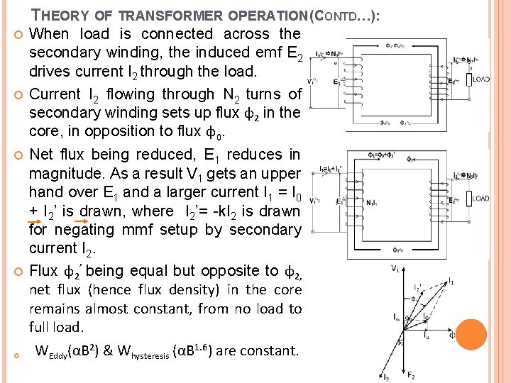
THEORY OF TRANSFORMER OPERATION (CONTD…): When load is connected across the secondary winding, the induced emf E 2 drives current I 2 through the load. Current I 2 flowing through N 2 turns of secondary winding sets up flux φ2 in the core, in opposition to flux φ0. Net flux being reduced, E 1 reduces in magnitude. As a result V 1 gets an upper hand over E 1 and a larger current I 1 = I 0 + I 2’ is drawn, where I 2’= -k. I 2 is drawn for negating mmf setup by secondary current I 2. Flux φ2’ being equal but opposite to φ2, net flux (hence flux density) in the core remains almost constant, from no load to full load. WEddy(αB 2) & Whysteresis (αB 1. 6) are constant.
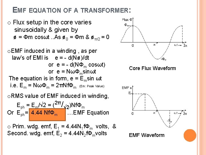
EMF EQUATION OF A TRANSFORMER: o Flux setup in the core varies sinusoidally & given by ø = Φm cosωt. . As ø 0 = Φm & øπ/2 = 0 o. EMF induced in a winding , as per law’s of EMI is e = - d(Nø)/dt or e = - d(NΦm cosωt) or e = NωΦmsinωt The equation is in form, e = Emsin ωt i. e. Em = NωΦm = 2πNfΦm (Em: Peak Value) Core Flux Waveform o. RMS value of EMF induced in winding, Eph = Em/√ 2 = (2π/√ 2)NfΦm Or Eph= 4. 44 NfΦm …EMF Equation o Prim. wdg. emf, E 1 = 4. 44 N 1 fΦm volts, & Second. wdg. emf, E 2 = 4. 44 N 2 fΦmvolts EMF Waveform
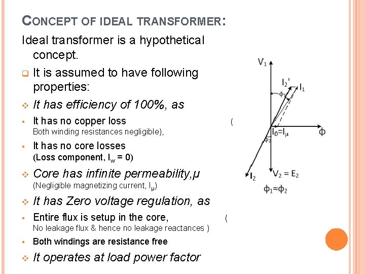
CONCEPT OF IDEAL TRANSFORMER: Ideal transformer is a hypothetical concept. q It is assumed to have following properties: v It has efficiency of 100%, as § It has no copper loss ( Both winding resistances negligible), § It has no core losses (Loss component, Iw = 0) v Core has infinite permeability, µ (Negligible magnetizing current, Iµ) v It has Zero voltage regulation, as § Entire flux is setup in the core, No leakage flux & hence no leakage reactances ) § Both windings are resistance free v It operates at load power factor (
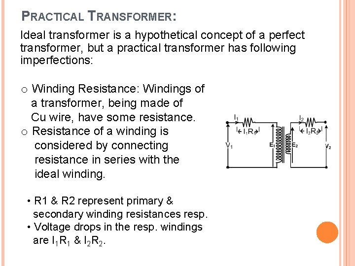
PRACTICAL TRANSFORMER: Ideal transformer is a hypothetical concept of a perfect transformer, but a practical transformer has following imperfections: o Winding Resistance: Windings of a transformer, being made of Cu wire, have some resistance. o Resistance of a winding is considered by connecting resistance in series with the ideal winding. • R 1 & R 2 represent primary & secondary winding resistances resp. • Voltage drops in the resp. windings are I 1 R 1 & I 2 R 2.
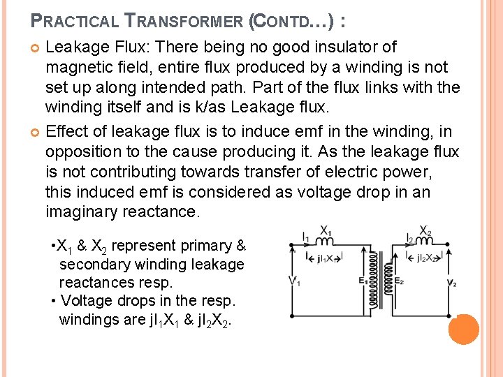
PRACTICAL TRANSFORMER (CONTD…) : Leakage Flux: There being no good insulator of magnetic field, entire flux produced by a winding is not set up along intended path. Part of the flux links with the winding itself and is k/as Leakage flux. Effect of leakage flux is to induce emf in the winding, in opposition to the cause producing it. As the leakage flux is not contributing towards transfer of electric power, this induced emf is considered as voltage drop in an imaginary reactance. • X 1 & X 2 represent primary & secondary winding leakage reactances resp. • Voltage drops in the resp. windings are j. I 1 X 1 & j. I 2 X 2.
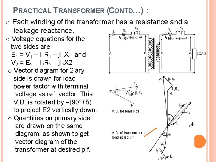
PRACTICAL TRANSFORMER (CONTD…) : o Each winding of the transformer has a resistance and a leakage reactance. o Voltage equations for the two sides are: E 1 = V 1 – I 1 R 1 – j. I 1 X 1, and V 2 = E 2 – I 2 R 2 – j. I 2 X 2 o Vector diagram for 2’ary side is drawn for load power factor with terminal voltage as ref. vector. This V. D. is rotated by –(90°+δ) to project E 2 vertically down. o Quantities on primary side are drawn on the same diagram, as shown to get vector diagram of the transformer at desired p. f. V. D. for load side V. D. of transformer on load at lag p. f.
LOSSES IN TRANSFORMER: o Two types of losses occur in a transformer: 1. Core loss or iron loss occur in iron core due to alternating flux set up in it, and 2. Copper loss occurs in the windings due to current flowing in them on loading the transformer. o Core Loss: These are of two types, a. Eddy current loss, and b. Hysteresis loss v Eddy Current Loss: Emf induced in the core sets up eddy current in the core, in turn eddy current loss occurs and is given by WE= Ke Bm 2 f 2 t 2 Watts, where Ke is eddy current constant, t is thickness of the core. v Hysteresis Loss: Mag. Core exhibits property of lagging of the flux density behind the magnetizing force when subjected to an alternating flux. This property k/as hysteresis causes energy loss, This loss is given by WH = Kh. Bm 1. 6 f. V Watts o Copper Loss: This is loss of power due to heat produced by currents in the windings. It is given by Pcu = I 12 R 1 + I 22 R 2 = I 12 R 01= I 22 R 02
THANK YOU