Satellite Communications Firoz Ahmed Siddiqui Satellite link design


")
")

 ---------- (4)")
 ---------- (6)")

 ---------- (8)")


")
 --------- (3)")
")

 --------- (6)")


- Slides: 71
Satellite Communications Firoz Ahmed Siddiqui
Satellite link design l l The cost to build and launch a GEO satellite is about $25, 000 per kg. Weight is the most critical factor in the design of any satellite, since the heavier the satellite the higher the cost. The overall dimensions of the satellite are critical because the spacecraft must fit within the confines of the launch vehicle. Typically the diameter of the spacecraft must be less than 3. 5 m.
Satellite link design l The weight of the satellite depends on two factors: the number and output power of the transponders and the weight of stationkeeping fuel.
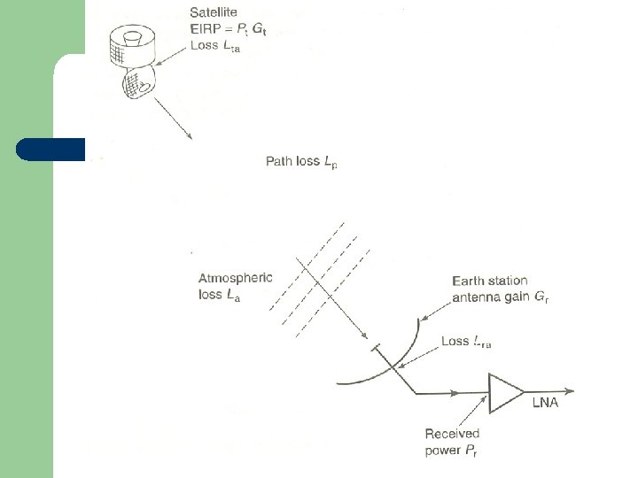
Satellite link design l Satellite link design is nothing but estimation of power that is to be transmitted from an earth station towards the satellite or from a satellite towards the earth station so that at both ends the received power is reasonable.
Satellite link design l This link design calculation takes into account several factors such as absorption of signal by the space through which it propagates, various noise sources present in the satellite system, gain of transmitting and receiving antennas, and also the uplink and downlink frequencies because the absorption of signal by the atmosphere varies with frequencies.
Satellite link design l l The design of uplink is simpler than the design of downlink, because any amount of required power can be generated in an earth station by using large number of vacuum devices. However this is not possible inside a satellite due to its limited size.
Satellite link design Figure – Flux density produced by an isotropic source.
Satellite link design l
Satellite link design l ---------- (1)
Satellite link design l ---------- (2)
Satellite link design Figure – Power received by an ideal antenna
Satellite link design l ---------- (3) ---------- (4)
Satellite link design l ---------- (5) ---------- (6)
Satellite link design l
Satellite link design l ---------- (7) ---------- (8)
Satellite link design l
Satellite link design l
Example - 1 l
Example Contd. l
Example Contd. l
Example Contd. l
Example - 2 l A satellite at a distance of 40, 000 km from a point on the earth’s surface radiates a power of 10 W from an antenna with a gain of 17 d. B in the direction of observer, operates at a frequency of 11 GHz. The receiving antenna has a gain of 52. 3 d. B. Find the received power.
l
Example Cond.
System Noise Temperature & G/T Ratio l l l Noise temperature is a useful concept in communications receivers. It provides a way of determining how much thermal noise is generated by active and passive devices in the receiving system. At microwave frequencies, a black body with physical temperature Tp degrees kelvin, generates electrical noise over a wide bandwidth. The noise power is given by
l
Calculation of System Noise Temperature
Calculation of System Noise Temperature l l l Figure shows a simplified communications receiver with an RF amplifier and single frequency conversion. This is the form used for all radio receivers. It is known as the superhet (superheterodyne). The superhet receiver has three main sybsystems: a front end (RF amplifier, mixer and local oscillator), an IF amplifier (IF amplifiers and filters), and a demodulator and baseband section.
Calculation of System Noise Temperature l l The RF amplifier in a satellite communications receiver must generate as little noise as possible, so it is called a low noise amplifier of LNA. The mixer and local oscillator form a frequency conversion stage that down converts the RF signal to a fixed intermediate frequency (IF), where the signal can be amplified and filtered accurately.
Calculation of System Noise Temperature
Calculation of System Noise Temperature l l l Many earth station receivers use the double superhet configuration shown in fig, which has two stages of frequency conversion. The front end of receiver converts the incoming RF signals to a first IF in the range 900 to 1400 MHz. This allows the receiver to accept all the signals transmitted from a satellite in a 500 MHz bandwidth. The next section of the receiver is called low noise block converter (LNB).
Calculation of System Noise Temperature l l l The 900 -1400 MHz signal is sent over a coaxial cable to a set-top receiver that contains another down-converter and a tunable local oscillator. The local oscillator is tuned to convert the incoming signal from a selected transponder to a second IF frequency. The second IF amplifier has a bandwidth equal to the spectrum of the transponder signal.
Calculation of System Noise Temperature
Calculation of System Noise Temperature l
Calculation of System Noise Temperature l --------- (1)
Calculation of System Noise Temperature l --------- (2) --------- (3)
Calculation of System Noise Temperature l --------- (4)
Calculation of System Noise Temperature l
Calculation of System Noise Temperature l --------- (5) --------- (6)
Numerical on System Noise Temperature l
l
l
Noise Figure and Noise Temperature l
l
G/T Ratio for Earth Stations l
G/T Ratio for Earth Stations l
Numerical l
l
l
l
Design of Downlinks l l l The design of any satellite communication is based on two objectives: Meeting a minimum C/N ratio for a specified percentage of time, and carrying the maximum revenue earning traffic at minimum cost. Any satellite link can be designed with very large antennas to achieve high C/N ratios under all conditions, but the cost will be high.
l l l The art of good system design is to reach the best compromise of system parameters that meets the specification at the lowest cost. All satellite communications links are affected by rain attenuation. Satellite links are designed to achieve reliabilities of 99. 5 to 99. 99%, over one year. That means the C/N ratio in the receiver will fall below the minimum permissible value for properation of the link for between 0. 5 and 0. 01 % of the specified time. This specified time is called outage.
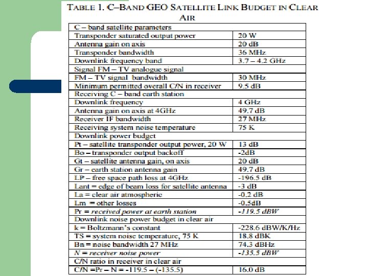
Link Budgets l l l C/N ratio calculation is simplified by the use of link budgets. A link budget is a tabular method for evaluating the received power and noise power in a radio link. Link budget use decibel units for all quantities so that signal and noise powers can be calculated by addition and subtraction.
l l Since it is impossible to design a satellite link at the first attempt, link budgets make the task much easier because, once a link budget has been established, it is easy to change any of the parameters and recalculate the result. The link budget must be calculated for an individual transponder, and must be recalculated for each of the individual links.
l Link budgets are usually calculated for a worst-case scenario like earth station located at the edge of the satellite coverage zone where the received signal is 3 d. B lower than in the center of the zone, maximum path length from the satellite to the earth station, a low elevation angle at the earth station, maximum rain attenuation on the link.
Table – C-Band Downlink Budget in Rain
Uplink Design l
l
l
l
l
Link Design Procedure l 1. 2. 3. The design procedure for a one-way satellite communication link can be summarized by the following 10 steps. The return link design follows the same procedure. Determine the frequency band in which the system must operate. Determine the communications parameters of the satellite. Determine the parameters of the transmitting and receiving earth stations.
l
l
10. Redesign the system by changing some parameters if the link margins are inadequate. Check that all parameters are reasonable, and that the design can be implemented within the expected budget.
DESIGN FOR SPECIFIED C/N l l The S/N ratio in the baseband channel of an earth station receiver is determined by the ratio of the carrier power to the noise power in the IF amplifier at the input to the demodulator. The noise present in the IF amplifier comes from many sources.
l l The noise in the earth station IF amplifier will have contributions from the receiver itself, the receiving antenna, sky noise, the satellite transponder from which it receives the signal, and adjacent satellites and terrestrial transmitters which share the same frequency band. When more than one C/N ratio is present in the link, we can add the individual C/N ratios reciprocally to obtain an overall C/N ratio.
DESIGN FOR SPECIFIED C/N l
DESIGN FOR SPECIFIED C/N l