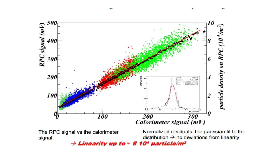
RPC performance v s FrontEnd electronics and detector
")


 to ionic charge (Qion) ratio Qp/Q ion= d/D D= is the")


 Pick up ns")


 N 0 = primary")

")


 Cluster. Size vs Graphite Resistivity (ρ) 0,")


 l d")


 Amp (a. u. ) Working strategy Actual")


 Time dependent neutron emission for JET pulse # 79613,")


- Slides: 38
RPC performance v. s. Front-End electronics and detector parameters R. Cardarelli Infn Tor-Vergata (Italy) XIV RPC workshop, Puerto Vallarta (Messico)
Performance optimization of the RPC • To optimize the RPC performance four elements should be considered 1. 2. 3. 4. The working mode: Qtot (rate capability and aging) The pick-up geometry: d/D (maximize Qp/Qtot ), spatial resolution and crosstalk The Front-End performance: AFE , BW and noise (rate capability spatial resolution) The Gap: Thickness, multi gap (Time resolution and rate capability )
Total charge v. s. working mode of RPC • Working mode of RPC: • Streamer • Saturated avalanche • Low saturated avalanche Total charge: 1 -0. 1 n. C 20 -40 p. C 1 -5 p. C
Pick-up charge (Qp) to ionic charge (Qion) ratio Qp/Q ion= d/D D= is the distance of pick-up electrode d = average drift distance of the electrons Streamer sreamer Saturate avalanche Low saturate avalanche d D Highly saturated avalanche d d Low saturated avalanche Electrons average drift distance Average ionic drift distance
Qion/Qp ratio for RPCs with different gap
Amplitude of electronic signal vs ionic signal in the pick-up electrode vd, el = average drift velocity of electrons Tel = d / vd, el vd, ion= average drift velocity of ions Tion= G / vd, ion (Vd, el/Vd, ion)=(mel/mion) G d Qel=Qion Tion >>>Tel Iel = Qel / Tel Vel = Iel x Zl Iion = Qion /Tion Vion = Iion x Zl Voltage amplitude of the electronic signal (Vel)>>> Vion
Pick–up and ionic signal for different gap(2 -1 -0. 5 mm) Pick up ns us Graphite electrode
Ionic charge/Pick-up charge v. s. Working mode of RPC • Working mode of RPC: • Streamer • saturated avalanche • Low saturated avalanche Qion/Qp: 2 -5 10 -20 20 -30
Pick-up and ionic charge v. s. electric field for different gap(2 -1 -0. 5 mm)
Pick-up signal duration time v. s. Electric Field for RPCs with different gap
Gas amplification in different working mode Gap (1 -2 mm) N 0 = primary ionization electrons Agas = gas amplification = (Qtot / N 0 )/ e-
Moving the amplification from the gas to the Front End electronics AFE (Amplification of the Front End electronics) AFE X Agas = k where k is the discriminator threshold AFE streamer – We assume it is 1 for streamers
Working point v. s. F. E. electronic amplification at constant threshold (see Pizzimento talk)
Total charge of the working point v. s. high voltage for different front-end electronic amplification for a 2 mm gap F. E. Amplification = K F. E. Amplification = 10 k
Pick-up charge for different working modes
Signal/Noise front-end electronic requirements •
Front End electronics Bandwidth for different working mode The front-end electronic requires an open-loop Bandwidth >> 3/Tel Streamer gap (2 mm) BW>> 30 MHz gap (1 mm) BW>> 60 MHz Avalanche gap (2 mm) BW>> 300 MHz gap (1 mm) BW>> 600 MHz
Pick-up electrode optimization (see Alunno Camelia poster) Cluster. Size vs Graphite Resistivity (ρ) 0, 018 Clustere. Size Induced Signal 0, 016 Crosstalk signal 0, 014 9 8 7 0, 012 6 0, 01 5 0, 008 4 0, 006 3 0, 004 2 0, 002 1 0 -0, 002 0 2 Ground. Wire 4 No. Ground. Wire Strip 6 8 Floating Adapted 10 0 0 50 100 150 200 250 300 350 KΩ /sq
Rate capability v. s. thickness of the RPC electrode • If I have a constant ionizing particles flux (ϴ) in the surface of the RPC, the voltage drop on the resistive electrode is: V= I x R =(Qtot x ϴ) x (ρ x d/S) S=surface of the RPC and d= thickeness • If the total charge (Qtot) of the avalance is constant, the rate capability is proportional to 1/d d=thickness of the electrode • Qtot(d)? • What is the minimum thickness (d) of the electrode?
Time resolution v. s. Gap thickness • The time resolution in the RPC (tests observation) is a linear function of the gap thickness fig 1. The gas, the resistivity and the electrical field have not a large impact in the resolution. • the mathematical model is still an open point in RPC. σ (ns) 1 0. 5 (mm) 2 1 Fig 1 time resolution v. s. gap thickness
Intrinsic spatial resolution
The limit of resistivity of the electrode material l (see Alessandro Rocchi) l d d d Waveforms
Total charge for synchronous ionization particle
The block diagram of the preamplifier For RPC tests we suggest CAEN A 1426 amplifier The same scheme can be used for both Silicon and Si. Ge technology for a comparison. Silicon technology Si. Ge technology R. Cardarelli - 22/11/2013 - Roma 25
Block diagram of a new full custom front-end chip See Salvatore Bruno and Luca Pizzimento talk vco Sinc in counter IN 1 Discr. Latch IN 8 Discr. Latch I/O CK Digital out Analog out Serial out (10 Gbit/sec)
conclusions • For the optimization of the RPC detector • Rate capability: Total charge, electrode thickness and resistivity • Spatial resolution: optimization pick-up pitch (centroid of charge) • Electronic: BW>>600 MHz, amplification>200 and noise < 1000 e- RMS • Time resolution: thickness of the gap and multi-gap
BJT Si v. s. Si. Ge • B JT performances • β=τc/τt • ft=1/τt • N= K*τt E τc= base life time τt = base transient time τt (Si) >> τt (Si. Ge) BJT Si diffusion Fermi energy B C HBT Si. Ge acceleration Fermi energy B E C
Strategy for the new front-end (Si. Ge) Amp (a. u. ) Working strategy Actual result for the RPC signal Time (nsec) R. Cardarelli - 22/11/2013 - Roma 29
Signal and noise from Si. Ge Amplifier and Silicon Amplifier Pulses recorded from a 500 micron diamond sensor irradiated by 241 Am source. Silicon amplifier Si. Ge amplifier
Si. Ge amplifier application on Resistive Plate Chamber detector A 1 mm gap RPC detector read out with a ATLAS like threshold (black), the new preamplifier in silicon technology (blue) and in Si. Ge technology (red) Using a more sensitive front end allows to operate the detector at a lower gain. Data from a cosmic ray test. Total delivered charge per count in the detector. The working point with different front ends is reported. Data from a cosmic ray test. Lower gain means lower charge per count. NOTE: the total charge reported is not the prompt charge collected in the front end. ATLAS like threshold Silicon new preamplifier Si. Ge new preamplifier R. Cardarelli - 22/11/2013 - Roma 31
Jet test Acquisition 100 m coaxial cable RG 6 Diamond sensor Preamplifier Pipe of Jet 400 °C R. Cardarelli - 22/11/2013 - Roma 32
Measurements and Results PHS for the n+6 Li a +T reaction measured at JET using the MSCA located 100 m away from the SCD+6 Li. F detector. Peak-1: A 1=52 m. V Peak-2: A 2=36 m. V Peak-1: CHN=88 Peak-2: CHN=121 P 2/P 1=1. 40 A 2/A 1=1. 44 R. Cardarelli - 22/11/2013 - Roma 33
Results in Counting Mode (C-27) Time dependent neutron emission for JET pulse # 79613, #79630 and #79640 measured with both MSCA operating in counting mode and compared to F. C. R. Cardarelli - 22/11/2013 - Roma 34
Si. Ge requirements for the full custom chip • Sinusoidal signal. Pulse signal. As low as possible. R. Cardarelli - 22/11/2013 - Roma 35
Block diagram and performance of a new full custom front-end chip vco Sinc in counter IN 1 Discr. Latch IN 8 Discr. Latch I/O CK Digital out Analog out Serial out (10 Gbit/sec)
Conclusions • The RPC performance is strictly connected with the gap thickness, resistivity and surface of the electrode, pick-up design and front-end electronics performance. • The Si. Ge technology has been chosen to realize a new high performance front-end for RPCs.
Electrodes thickness S d Qtot = Qion + Qel G D Qel/Qtot= d / (2 x S/εr + G)