Reference Systems Projections Datums Coordinates and Surveys Source
 and Surveys Source: Peter H. Dana, The Geographer's Craft")


")

")
")


 n Origin n 31: 10 North 100: 00 West standard parallels")


 • Townships, square with six miles on each side,")

")


- Slides: 54
Reference Systems (Projections, Datums, Coordinates) and Surveys Source: Peter H. Dana, The Geographer's Craft Project, Department of Geography, The University of Colorado at Boulder, http: //www. ncgia. ucsb. edu/education/curricula/giscc used with permission
Projections n n n World’s not flat (despite what you have heard from Dr. K!) We want to tie our plane surveys to global systems Submeter accuracy n n GPS Satellite imagery
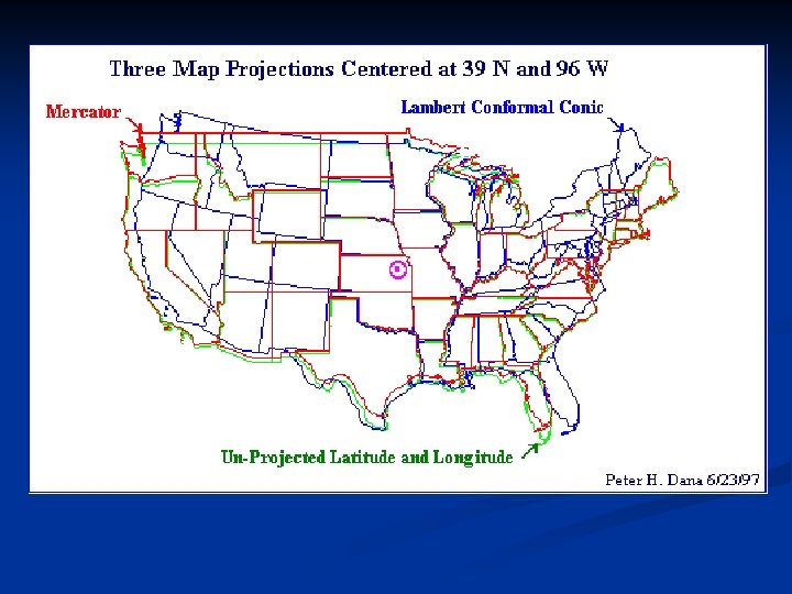
Projections n n n Conformality Distance Direction Scale Area
Mercatur Lambert Lat-Long (unprojected)
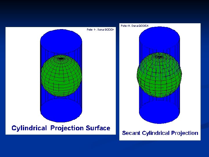
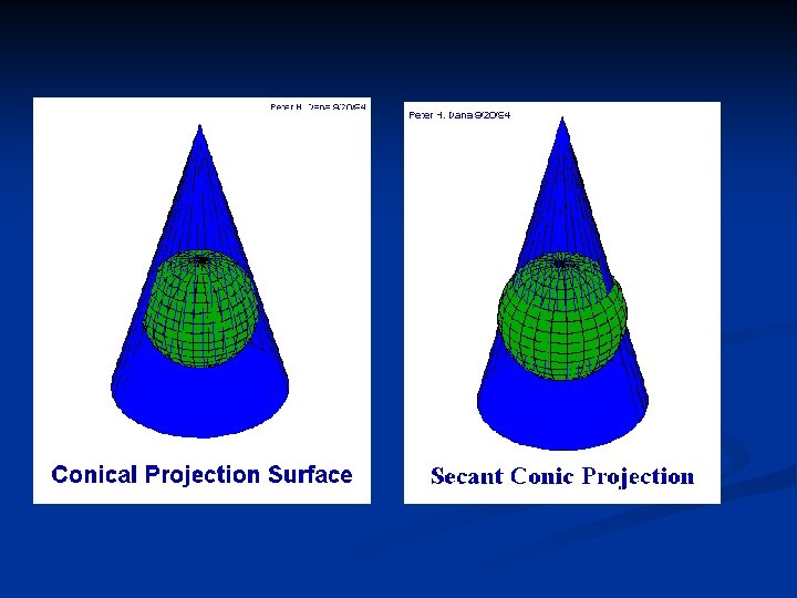
Scale true on 2 parallels
Secant at 45° (minimizes shape distortion)
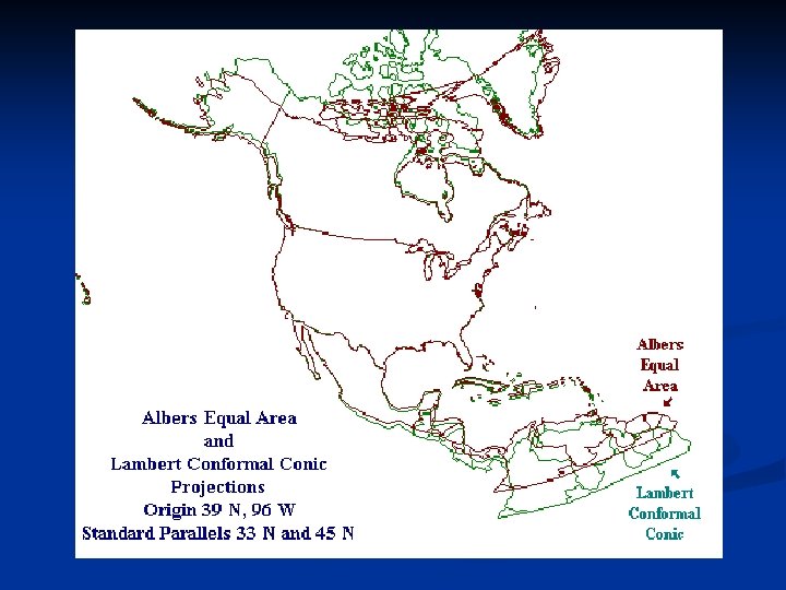
Note shift of latitude lines (minimizes area exaggeration)
Constant azimuth for lines
Preserve distance along great circle
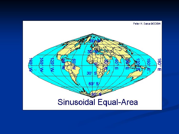
Pseudocylindrical
North American Projections Equal Area Equal Dist.
Iowa State Plane USGS topos
Similar to Gall, no secant
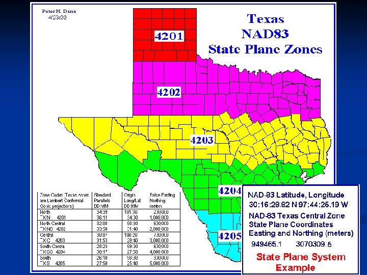
State Systems (hybrids) n Origin n 31: 10 North 100: 00 West standard parallels n n 27: 25 North 34: 55 North
Iowa DOT Lambert Hybrid
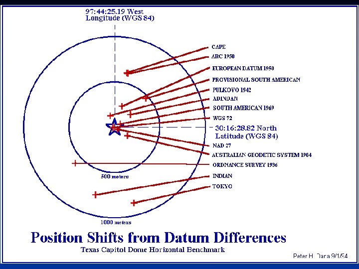
Datums 1. 2. 3. Define the shape of the earth Range from flat-earth to complex Wrong datum may produce 100 s of meters in error cartography, surveying, navigation, and astronomy, geodesy
Geometric Earth Models n Early ideas of the figure of the earth resulted in descriptions of the earth as an oyster (The Babylonians before 3000 B. C. ), a rectangular box, a circular disk, a cylindrical column, a spherical ball, and a very round pear (Columbus in the last years of his life). You are here!
Geometric Earth Models n Flat earth models are still used for plane surveying, over distances short enough so that earth curvature is insignificant (less than 10 kms).
Looks like a sphere, but flat here, and here
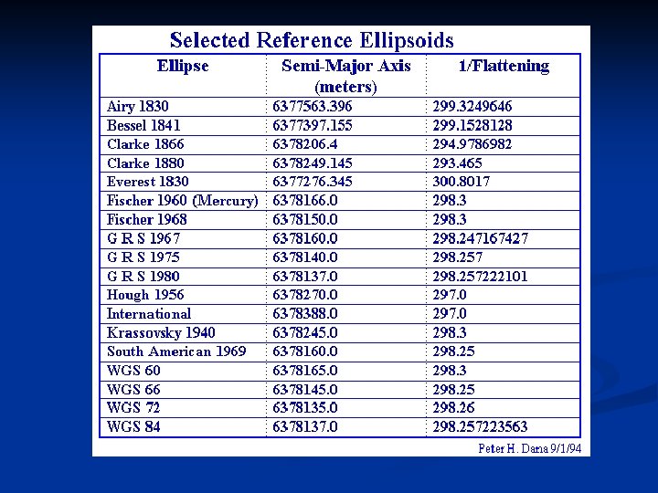
The best ellipsoidal models can represent the shape of the earth over the smoothed, averaged sea-surface to within about onehundred meters.
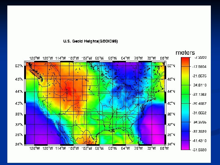
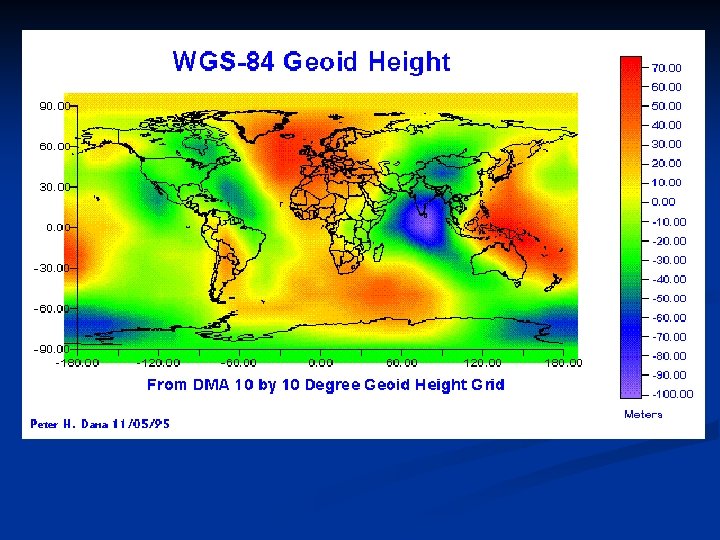
n n n Sea level: average surface of the oceans ( is far more complex) Tidal forces and gravity cause surface to vary by hundreds of meters! Gravity models and geoids are used to represent local variations in gravity that change the local definition of a level surface
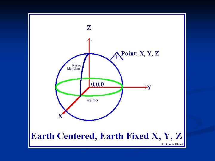
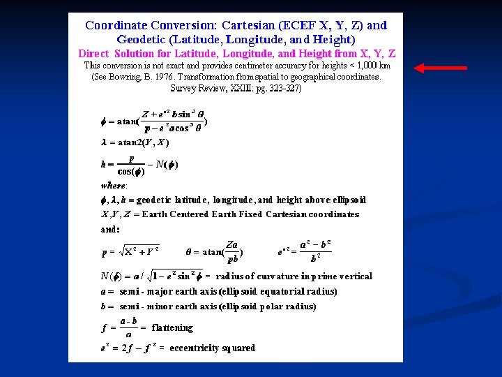
Geodetic Height
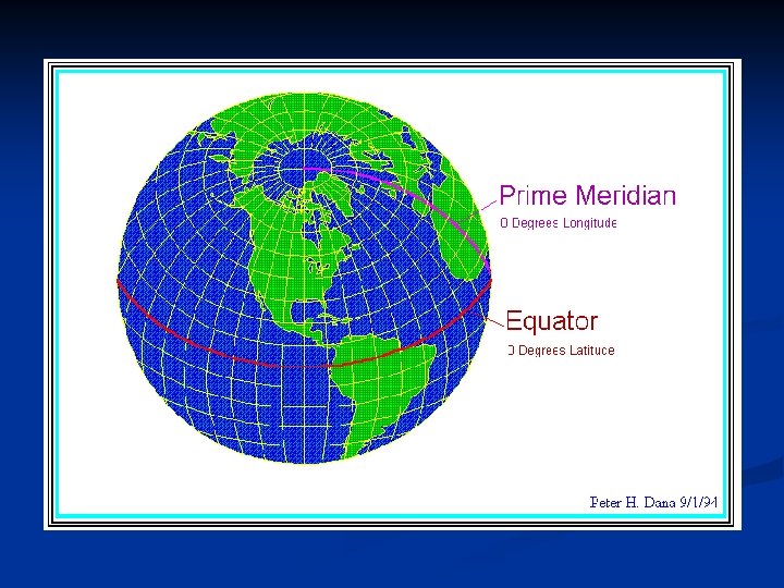
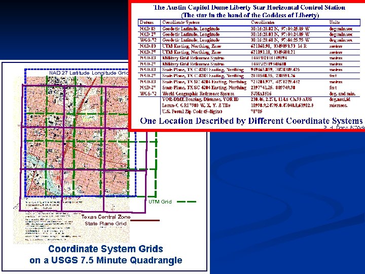
Coordinate Systems Based on … n n Datums Units Projections Reference systems
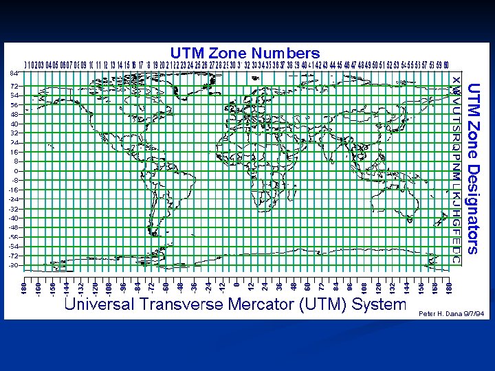
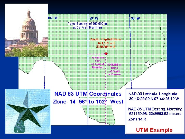
UTM n n Note false easting False northing in southern hemisphere
Local Adjustments n n May need a scaling factor to make total station measurements match regional coordinate systems e. g. , Iowa DOT develops a scaling factor for each project n n Based on an accurately measured point in the center of the project Not using a scaling factor can produce a 12’ error 30 miles from project center
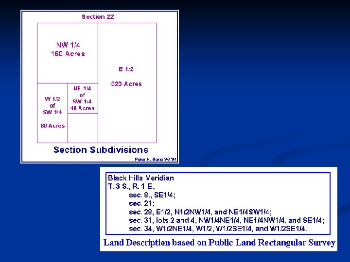
Public Land Rectangular Surveys (USPLS) • Townships, square with six miles on each side, are numbered with reference to a baseline and principal meridian. • actually, few townships are truly square due to convergence of the meridians. • Ranges are the distances and directions from baseline and meridian expressed in numbers of townships. • Every four townships, a new baseline is established so that orthogonal meridians can remain north oriented.
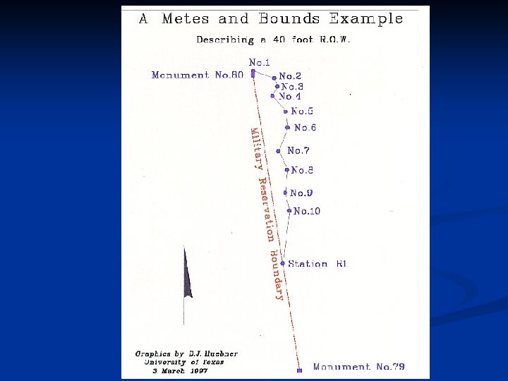
Metes and Bounds • Metes and Bounds identify the boundaries of land parcels by describing lengths and directions of a sequence of lines forming the property boundary.
Linear Referencing Systems n Methods n n n n Milepost Milepoint Cogo (project coordinates) Lat-Long Projected coordinates Address Literal description
Linear Referencing Systems n n CAD/cartography Linear Datum n n n Anchor points Anchor sections Reference points
DOT Hwy Surveys 1. The use of photogrammetry, CAD, GPS to establish design controls and details 2. Survey methods: a) Ground survey: windshield, transit, level, rod, chain, EDM, total station b) GPS, DGPS, Kinematic GPS - smaller crew needed c) Photogrammetry (with control points established by a or b above), including digital photography, orthos, softcopy d) LIDAR (Light Detection and Ranging)
Survey Types 1. Desk Study 2. Reconnaissance/cornerstone survey (used to validate or even provide a base map of culture and topography sufficient to select prelim. aligns. ) width usu. 0. 4 – 0. 6 of total length of project, 1”=100’ or 200’, 2 -5’ contours 3. Location or Preliminary (identify BOP, EOP, and PIs, and key features (drainage, environmental land, archeological/cultural, traffic) 4. Final or Construction survey – centerline by station, slope stakes, drainage, edge of pavement, offset, permanent land corners, right-of-way markers
Wright, Paul, Highway Engineering, 6 th Ed. Wiley, 1996