Processeurs de Signaux et Images 2 nde partie


![Processor design (3/3) Controller Datapath Rst Contrôle (FSM) Code. Op [5: 0 ] ld. Processor design (3/3) Controller Datapath Rst Contrôle (FSM) Code. Op [5: 0 ] ld.](https://slidetodoc.com/presentation_image/fd937e747afea7b882d64d290eefbc1e/image-41.jpg)

- Slides: 42

Processeurs de Signaux et Images 2 nde partie Cours n° 2 -3 Processeurs à usage universel, Processeurs dédiés à un domaine d’applications (ASIPs) Amer Baghdadi Amer. Baghdadi@telecom-bretagne. eu Télécom Bretagne – Département Electronique Master 2 Recherche - STIP Signal, Télécoms, Image, Parole Novembre 2009

Course outline C 2 -C 3 : General purpose processors q Architecture of General Purpose Processors ÄDatapath unit ÄControl unit ÄExecution cycles of an instruction ÄArchitecture considerations q Advanced architecture concepts (Pipeline, superscalar and VLIW architectures, Caches, Princeton and Harvard) q Programming model q Application Specific Instruction-set Processors (ASIPs) q Introducing the lab work: design of an elementary processor Reference book &EMBEDDED SYSTEM DESIGN: A Unified Hardware/Software Introduction, by F. Vahid (UCR) and T. Givargis (UCI). page 2 Département Électronique - A. BAGHDADI Processeurs de Signaux et Images - 2 nde partie

Introduction n General-Purpose Processor ¨ Processor designed for a variety of computation tasks ¨ Low unit cost, in part because manufacturer spreads NRE over large numbers of units n Motorola sold half a billion 68 HC 05 microcontrollers in 1996 alone ¨ Carefully designed since higher NRE is acceptable n Can yield good performance, size and power ¨ Low NRE cost, short time-to-market/prototype, high flexibility n User just writes software; no processor design ¨ “microprocessor” – “micro” used when they were implemented on one or a few chips rather than entire rooms page 3 Département Électronique - A. BAGHDADI Processeurs de Signaux et Images - 2 nde partie

Basic Architecture n Control unit and datapath similarity to single-purpose processor Processeur Unité de contrôle ¨ Note n Unité opérative Command e État Contrôleur Registres Key differences ¨ Datapath is general ¨ Control unit doesn’t store the algorithm – the algorithm is “programmed” into the memory page 4 UAL PC IR E/S Mémoire Département Électronique - A. BAGHDADI Processeurs de Signaux et Images - 2 nde partie

Datapath Operations n Load ¨ n Processeur Read memory location into register Execute ¨ Unité de contrôle UAL Command e État Contrôleur 1+1 1 Registres Input certain registers through ALU, store back in register PC n Unité opérative 1 0 IR Store ¨ Write register to memory location E/S Mémoire page 5 Département Électronique - A. BAGHDADI Processeurs de Signaux et Images - 2 nde partie … 10 1 0 … 1 1

Control Unit n Control unit: configures the datapath operations ¨ n Sequence of desired operations (“instructions”) stored in memory – “program” Instruction cycle – broken into several suboperations, each one clock cycle, e. g. : Processeur Unité opérative Unité de contrôle Contrôleur UAL Command e État Fetch: Get next instruction into IR PC IR ¨ Decode: Determine what the instruction means ¨ Fetch operands: Move E/S data from memory to 100 load R 0, M[500] datapath register 500 101 Inc R 1, R 0 Mémoire 501 ¨ Execute: Move data 102 store M[501], R 1 through the ALU ¨ Store results: Write data from register to memory page 6 Département Électronique - A. BAGHDADI Processeurs de Signaux et Images - 2 nde partie Registres ¨ R 0 … 10 … R 1

Control Unit Sub-Operations n Processeur Fetch Instruction ¨ Get next instruction into IR : program counter, always points to next instruction ¨ IR : holds the fetched instruction Unité de contrôle Contrôleur ¨ PC page 7 Unité opérative UAL Command e État Registres PC 100 Adresse IR R 0 E/S … load R 0, M[500] 100 load 500 10 101 Inc R 1, R 0 Mémoire 501 … 102 store M[501], R 1 Département Électronique - A. BAGHDADI Processeurs de Signaux et Images - 2 nde partie R 1

Control Unit Sub-Operations n Decode ¨ Determine the instruction type Processeur Unité de contrôle Contrôleur Unité opérative UAL Command e État Registres PC 100 load IR R 0, M[500] R 0 E/S … 100 load R 0, M[500] 500 10 101 Inc R 1, R 0 Mémoire 501 … 102 store M[501], R 1 page 8 Département Électronique - A. BAGHDADI Processeurs de Signaux et Images - 2 nde partie R 1

Control Unit Sub-Operations n Fetch operands ¨ Move data from memory to datapath register Processeur Unité de contrôle Contrôleur Unité opérative UAL Command e État Registres PC 100 load IR R 0, M[500] R 0 E/S … 100 load R 0, M[500] 500 10 101 Inc R 1, R 0 Mémoire 501 10 … 102 store M[501], R 1 page 9 Département Électronique - A. BAGHDADI Processeurs de Signaux et Images - 2 nde partie R 1

Control Unit Sub-Operations n Execute ¨ Move data through the ALU ¨ This particular instruction (load R 0, M[500]) does nothing during this suboperation Processeur Unité de contrôle Contrôleur Unité opérative UAL Command e État Registres PC 100 10 load IR R 0, M[500] R 0 E/S … 100 load R 0, M[500] 500 10 101 Inc R 1, R 0 Mémoire 501 … 102 store M[501], R 1 page 10 Département Électronique - A. BAGHDADI Processeurs de Signaux et Images - 2 nde partie R 1

Control Unit Sub-Operations n Processeur Store ¨ Write data from register to memory Unité de contrôle Contrôleur Unité opérative UAL Command e État Registres ¨ This particular instruction (load R 0, M[500]) does nothing during this suboperation page 11 PC 100 10 load IR R 0, M[500] R 0 E/S … 100 load R 0, M[500] 500 10 101 Inc R 1, R 0 Mémoire 501 … 102 store M[501], R 1 Département Électronique - A. BAGHDADI Processeurs de Signaux et Images - 2 nde partie R 1

Instruction Cycles PC=10 0 Fetch Decode Fetch Exe inst. oprends c. Processeur Store results Unité de contrôle Unité opérative UAL Command e État clk Contrôleur Registres PC 100 IR R 0 E/S … load R 0, M[500] 100 load 500 101 Inc R 1, R 0 Mémoire 501 10 … 102 store M[501], R 1 page 12 Département Électronique - A. BAGHDADI Processeurs de Signaux et Images - 2 nde partie R 1

Instruction Cycles PC=10 0 Fetc Decode Fetch Exe hinst. oprends c. Processeur Store results Unité de contrôle hinst. clk oprends Contrôleur Exe c. UAL 1+1 1 Command e État clk PC=10 1 Fetc Decode. Fetch Unité opérative Registres Store results PC 101 1 10 IR R 00 E/S … 100 load R 0, M[500] 500 10 R 1, R 0 Inc R 1, 101 Inc Mémoire 501 … 102 store M[501], R 1 page 13 Département Électronique - A. BAGHDADI Processeurs de Signaux et Images - 2 nde partie R 1

Instruction Cycles PC=10 0 Fetc Decode Fetch Exe hinst. oprends c. Processeur Store results Unité de contrôle hinst. oprends Contrôleur Exe c. Registres Store results clk PC 102 PC=10 2 Fetc Decode. Fetch hinst. clk page 14 oprends Exe c. UAL Command e État clk PC=10 1 Fetc Decode. Fetch Unité opérative Store results 10 IR R 0 E/S … 100 load R 0, M[500] 500 10 101 Inc R 1, R 0 Mémoire 501 … store M[501], R 1 102 store Département Électronique - A. BAGHDADI Processeurs de Signaux et Images - 2 nde partie 11 R 1

Architectural Considerations n N-bit processor ¨ N-bit ALU, registers, buses, memory data interface ¨ Embedded: 8 -bit, 16 bit, 32 -bit common ¨ Desktop/servers: 32 bit, even 64 n PC size determines address space page 15 Processor Control unit Datapath unit Command e Status Controller UAL Registers PC IR E/S Memory Département Électronique - A. BAGHDADI Processeurs de Signaux et Images - 2 nde partie

Architectural Considerations n Clock frequency ¨ Inverse of clock Processor Control unit Datapath unit period be longer than longest register to register delay in entire processor Controller ¨ Must ¨ Memory access is often the longest page 16 Command e Status UAL Registers PC IR E/S Memory Département Électronique - A. BAGHDADI Processeurs de Signaux et Images - 2 nde partie

Architectural Considerations n Performance ¨A can be improved through: faster clock (technology limitations!) ¨ Pipeline: dividing the instruction execution in several stages and superposing them ¨ Multiple ALUs to execute multiple instruction flows (concurrently) n Superscalar and V LIW architectures page 17 Département Électronique - A. BAGHDADI Processeurs de Signaux et Images - 2 nde partie

Pipelining: Increasing Instruction Throughput Wash 1 2 3 4 5 6 7 8 Non-pipelined Dry Two resources available Pipelined 1 2 3 4 5 6 7 8 non-pipelined dish cleaning Fetch-inst. Decode Fetch ops. Execute Store res. 1 2 3 4 5 6 7 8 time pipelined dish cleaning time 1 2 3 4 5 6 7 8 Pipelined 1 2 3 4 5 6 7 8 1 st instruction 1 2 3 4 5 6 7 8 time pipelined instruction execution page 18 Département Électronique - A. BAGHDADI Processeurs de Signaux et Images - 2 nde partie

Superscalar architecture n Superscalar ¨ ¨ Scalar operation: being carried out on one or two numbers (contrary to a vector or matrix operation) Fetches instructions in packets n Static scheduling (at compilation time) or dynamic (at execution time) n In case of dynamic scheduling : requires extensive hardware to detect independent instructions Cache/ memory Fetch Decode& Ordre multiple instructions FU FU Sequential flow of instructions Registers page 19 Département Électronique - A. BAGHDADI Processeurs de Signaux et Images - 2 nde partie FU Multiple functional units (FU)

VLIW architecture n VLIW (Very Long Instruction Word) : long instruction (128 -1024 bits) composed of several independents operations (rather than one) ¨ Equivalent to a superscalar architecture with a static scheduling ¨ Currently growing in popularity Cache/ memory Fetch one multi-operation instruction FU FU Registers page 20 Département Électronique - A. BAGHDADI Processeurs de Signaux et Images - 2 nde partie FU Plusieurs unités fonctionnelles (UF)

Two memory architectures n Princeton Processor (Von Neumann) C Fewer memory wires C Simple Program memory Data memory Memory (program and data) implementation Harvard Princeton (Von Neumann) C Simultaneous program and data memory access (Fetch inst. andÉlectronique Fetch - A. BAGHDADI page 21 Département Processeurs de Signaux et Images - 2 nde partie

Cache Memory n Memory access may be slow n Cache is small but fast memory close to processor copy of part of memory ¨ Hits and misses Fast/expensive technology, usually on the same chip Processor ¨ Holds Cache Memory Slower/cheaper technology, usually on a different chip page 22 Département Électronique - A. BAGHDADI Processeurs de Signaux et Images - 2 nde partie

Programmer’s View n Programmer doesn’t need detailed understanding of architecture ¨ Instead, n needs to know what instructions can be executed Two levels of instructions: ¨ Assembly level ¨ Structured languages (C, C++, Java, etc. ) n Most development today done using structured languages ¨ But, some assembly level programming may still be necessary ¨ Drivers: portion of program that communicates with and/or controls (drives) another device n Often have detailed timing considerations, extensive bit manipulation pagen 23 Assembly level may be best fordethese Département Électronique - A. BAGHDADI Processeurs Signaux et Images - 2 partie nde

Assembly-Level Instructions Instruction 1 op. code operand 1 operand 2 Instruction 2 op. code operand 1 operand 2 Instruction 3 op. code operand 1 operand 2 Instruction 4 op. code operand 1 operand 2. . . n Instruction Set ¨ Defines the legal set of instructions for that processor Data transfer: memory/register, register/register, I/O, etc. n Arithmetic/logical: move register through ALU and back n Branches: determine next PC value when not just PC+1 n page 24 Département Électronique - A. BAGHDADI Processeurs de Signaux et Images - 2 nde partie

A Simple Instruction Set Assembly instruct. First byte Second byte Operation MOV Rn, direct 0000 Rn direct Rn = M(direct) MOV direct, Rn 0001 Rn direct M(direct) = Rn MOV @Rn, Rm 0010 Rn MOV Rn, #immed. ADD Rn, Rm 0011 Rn 0100 Rn Rm Rn = Rn + Rm SUB Rn, Rm 0101 Rn Rm Rn = Rn - Rm JZ Rn, relative 0110 Rn op. cod e page 25 Rm immédiat relatif operands M(Rn) = Rm Rn = immediate PC = PC + relative (if Rn = 0) Département Électronique - A. BAGHDADI Processeurs de Signaux et Images - 2 nde partie

Addressing Modes Register-file contents Memory contents Operand field Immediate data Register-direct Register Address data Registerindirect Register Address Memory Address Direct Memory Address data Indirect Memory Address data page 26 Département Électronique - A. BAGHDADI Processeurs de Signaux et Images - 2 nde partie

Sample Program C Program Equivalent assembly program 0 MOV R 0, #0; // total = 0 int total = 0; 1 MOV R 1, #10; // i = 10 for (int i=10; i!=0; i--) 2 MOV R 2, #1; // constant 1 3 MOV R 3, #0; // constant 0 JZ R 1, Next; // Branch if i=0 total += i; // next instructions. . . Loop: 5 ADD R 0, R 1; // total += i 6 SUB R 1, R 2; // i-- 7 JZ R 3, Loop; // Branch Next: page 27 // next instructions. . . Département Électronique - A. BAGHDADI Processeurs de Signaux et Images - 2 nde partie

Programmer Considerations n Program and data memory space ¨ Embedded processors often very limited n e. g. , 64 Kbytes program, 256 bytes of RAM (expandable) n Registers: How many are there? ¨ Only n I/O ¨ How n a direct concern for assembly-level programmers communicate with external signals? Interrupts page 28 Département Électronique - A. BAGHDADI Processeurs de Signaux et Images - 2 nde partie

Application-Specific Instruction-set Processors (ASIPs) n General-purpose processors ¨ Sometimes too general to be effective in demanding application n e. g. , video processing – requires huge video buffers and operations on large arrays of data, inefficient on a GPP n Single-purpose processor ¨ High n NRE, not programmable ASIPs – targeted to a particular domain ¨ Contain architectural features specific to that domain n e. g. , embedded control, digital signal processing, video processing, network processing, telecommunications, etc. ¨ Still programmable page 29 Département Électronique - A. BAGHDADI Processeurs de Signaux et Images - 2 nde partie

A Common ASIP: the DSP (Digital Signal Processor) n For signal processing applications ¨ Large amounts of digitized data, often streaming ¨ Data transformations must be applied fast ¨ e. g. , cell-phone voice filter, digital TV, music synthesizer n DSP features ¨ Several instruction execution units ¨ Multiple-accumulate single-cycle instruction, other instrs. ¨ Efficient vector operations – e. g. , add two arrays n Vector ALUs, loop buffers, etc. page 30 Département Électronique - A. BAGHDADI Processeurs de Signaux et Images - 2 nde partie

Example: TMS 320 C 67 x core page 31 Département Électronique - A. BAGHDADI Processeurs de Signaux et Images - 2 nde partie

Another Common ASIP: Microcontroller n For embedded control applications ¨ Reading sensors, setting actuators ¨ Mostly dealing with events (bits): data is present, but not in huge amounts ¨ e. g. , VCR, disk drive, digital camera (assuming SPP for image compression), washing machine, microwave oven n Microcontroller features ¨ On-chip peripherals n Timers, analog-digital converters, serial communication, etc. n Tightly integrated for programmer, typically part of register space ¨ On-chip program and data memory ¨ Direct programmer access to many of the chip’s pins ¨ Specialized instructions for bit-manipulation and other lowpage 32 Département Électronique - A. BAGHDADI Processeurs de Signaux et Images - 2 partie level operations nde

Example: Sharp LH 77790 B microcontroller page 33 Département Électronique - A. BAGHDADI Processeurs de Signaux et Images - 2 nde partie

Trend: Even More Customized ASIPs n n In the past, microprocessors were acquired as chips Today, we increasingly acquire a processor as Intellectual Property (IP) ¨ e. g. , n synthesizable VHDL model Opportunity to add a custom datapath hardware and a few custom instructions, or delete a few instructions ¨ Can have significant performance, power and size impacts ¨ Problem: need compiler/debugger for customized ASIP n Remember, most development uses structured languages n One solution: automatic compiler/debugger generation ¨ e. g. , www. tensillica. com n Another ¨ e. g. , page 34 solution: retargettable compilers www. improvsys. com (customized VLIW architectures) Département Électronique - A. BAGHDADI Processeurs de Signaux et Images - 2 nde partie

Selecting a Microprocessor n Criteria ¨ Technical: speed, power, size, cost ¨ Other: development environment, prior expertise, licensing, etc. n Speed: how evaluate a processor’s speed? ¨ Clock speed – but instructions per cycle may differ ¨ Instructions per second – but work per instr. may differ ¨ Dhrystone: Synthetic benchmark, developed in 1984. Dhrystones/sec. n MIPS: 1 MIPS = 1757 Dhrystones per second. D-MIPS commonly used today. ¨ So, 750 MIPS = 750*1757 = 1, 317, 750 Dhrystones per second ¨ SPEC: set of more realistic benchmarks, but oriented to desktops ¨ EEMBC – EDN Embedded Benchmark Consortium, page 35 Département Électronique - A. BAGHDADI Processeurs de Signaux et Images - 2 partie www. eembc. org nde

Design of an elementary (yet general purpose!) processor page 36 Département Électronique - A. BAGHDADI Processeurs de Signaux et Images - 2 nde partie

Presentation of the elementary processor n n n 8 -bits general purpose processor Based on accumulator register named ACCU (8 bits) Four instructions Mnemonic Instruction coding Description NOR 00 AAAAAA ACCU = ACCU NOR Mem[AAAAAA] ADD 01 AAAAAA ACCU = ACCU + Mem[AAAAAA], update STA 10 AAAAAA Mem[AAAAAA] = ACCU 11 DDDDDD If Carry = 0 PC = DDDDDD Else clear Carry (Carry=0) JCC n the Carry Each instruction is coded on 8 bits. Two bits to code the type of the operation (op. code) and 6 bits to code the operand or the address of the operand in the memory according to the type of the instruction. [Instruction-set source : http: //www. tuhh. de/~setb 0209/cpu/ by T. Böscke] page 37 Département Électronique - A. BAGHDADI Processeurs de Signaux et Images - 2 nde partie

Example of a test program Mem Adr Binary (hexa) content Assembler instructions Comments 000000 : 00001000 (0 x 08) NOR 0 b 001000 ; ACCU = ACCU NOR M[001000] 000001 : 01000111 (0 x 47) ADD 0 b 000111 ; ACCU = ACCU + M[000111] 000010 : 10000110 (0 x 86) STA 0 b 000110 ; M[000110] = ACCU 000011 : 11000100 (0 x. C 4) JCC 0 b 000100 ; if Carry = 0 then PC = 000100 else clear Carry 000100 : 11000100 (0 x. C 4) JCC 0 b 000100 ; PC = 000100 (Carry has been cleared) 000101 : 0000 (0 x 00) 000110 : 0000 (0 x 00) 000111 : 01111110 (0 x 7 E) 001000 : 1111 (0 x. FF) 001001 : 00000000 (0 x 00) … … … 111111 page 38 : Data… 0000 (0 x 00) Département Électronique - A. BAGHDADI Processeurs de Signaux et Images - 2 nde partie (Carry)

Processor design (1/3) n Consider the basic architecture model (slide n° 4) n Consider the instruction set, the number of registers, and the (eventual) imposed architectural specifications/constraints n Using the design methodology presented previously (course n° 1) page 39 Département Électronique - A. BAGHDADI Processeurs de Signaux et Images - 2 nde partie

Processor design (2/3) Algorithm – FSMD Clear PC & IR & Carry & Registers; while (1) { Fetch Inst (read one instruction); Decode the instruction; if ( Code. Op=00 or Code. Op=01 ) { Fetch Operand (read the operand to R 1); if Code. Op=00 Execute NOR (ACCU = ACCU NOR M[AAAAAA]); else Execute ADD (ACCU = ACCU + M[AAAAAA] Update the Carry); } else if Code. Op=10 { Execute STA (Mem[AAAAAA] = ACCU); } else { Execute JCC (if Carry=0 PC=DDDDDD else Carry=0); } } page 40 Département Électronique - A. BAGHDADI Processeurs de Signaux et Images - 2 nde partie
![Processor design 33 Controller Datapath Rst Contrôle FSM Code Op 5 0 ld Processor design (3/3) Controller Datapath Rst Contrôle (FSM) Code. Op [5: 0 ] ld.](https://slidetodoc.com/presentation_image/fd937e747afea7b882d64d290eefbc1e/image-41.jpg)
Processor design (3/3) Controller Datapath Rst Contrôle (FSM) Code. Op [5: 0 ] ld. PC inc. PC clr. PC PC [7: 0 ] sel. UA L C [7: 6 ] IR C UAL NOR ou ADD [7: 0 ] ld clr C C ld. ACCU ld. IR ACCU ld. R 1 [5: 0 ] sel. AD R 1 [5: 0 ] R 1 [7: 0 ] Mux 0 we. M en. M Adr [5: 0 ] Data. I n [7: 0 ] Data. Ou t [7: 0 ] Memory page 41 Département Électronique - A. BAGHDADI Processeurs de Signaux et Images - 2 nde partie

It is time to practice CAD tools (Computer-aided design) will be used to implement the architecture which you will propose for this processor page 42 Département Électronique - A. BAGHDADI Processeurs de Signaux et Images - 2 nde partie
 Signaux de communication
 Signaux lumineux otto dix
 Continus
 Schéma petit signaux transistor bipolaire
 L'alimentation du dauphin
 Partie de campagne renoir
 Fonction partie entiere
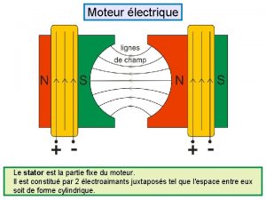
 Fixé au stator
 Chimie partie 2
 Synecdoque et métonymie
 Partie theorique
 Partie prenante management
 Glisse nombre
 La route de chlifa résumé
 Gastro entérologue définition
 Tableau dixième centième
 Où se trouve le centre de la terre
 Plan zatrudnienia wzór
 Partie de poisson
 Shared nde
 Darbelerin kaybettirdiği topraklar
 Nde telkom
 Nde schools
 Nde lessons
 What does nde stand for
 Cumhuriyet dönemi'nde tiyatro 1923 1950
 Level of consciousness
 Alçalıcı hava hareketi
 Nde rule 51 technical assistance document
 How to save images on google images
 Real vs virtual images
 Yahoo.com.yw
 Hi/ho = di/do
 Images search yahoo
 Observations images
 Complementary angles real world example
 Digital images definition
 Kumari kandam
 Luke 6 27-38
 Find similar images
 Drum plotter working
 Muscular force images
 Splendid comparative and superlative
