Preliminary Design Review Senior Design Team 05 Gleason


- Slides: 44

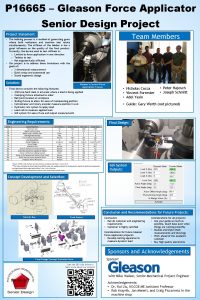
Preliminary Design Review Senior Design Team 05: Gleason Works – Chamfering and Deburring Project

Team Introduction ® ® ® ® ® Project Manager: Vincenzo Mansueto -ME Lead Engineer: Matthew Liddick -ME Team Member: Brian Banazwski -ME Team Member: Mark Trotta -ME Team Member: Julie Wilcox -ME Team Member: Phil Raduns -EE Team Member: Greg Baesl -ISE Faculty Advisor: Bill Scarbrough Gleasons Representative: Eric Mundt

What is Fly Cutter Chamfering

Project Description ® Goal ® Upper level design of a stand-alone fly cutter chamfering machine ® Final deliverable ® Upper level assembly drawings ® Machine component recommendations

Company Background Leading world-wide supplier of gear cutting technology ® Subdivision of Gleason Corporation ® Primary Market ® Automobile and truck industries ® Secondary Market ® Aerospace, Farm, Construction, Marine ®

Defining the Need ® Cutting process for creating gears leaves behind sharp edges and burrs ® ® Danger to workers Gear strength Contamination Aesthetic

Project Background ® Two processes currently used Subsystem on the Phoenix II machine ® One time modification of the GTR 250 CNC ® ® The Gleason Works has requested a new design for a marketable stand-alone chamfering and deburring machine. ® New design may also incorporate ideas from current systems

Project Scope ® Design Package ® Pro. E top level drawings ® Bill of Materials ® Market assessment ® Feasibility assessment ® Mathematical model to disprove interference ® No Physical Prototype

Work Breakdown Structure ® Design concepts ® Patents ® Methods of Removing Material ® Methods of Movement Tool Piece ® Axis Systems ® ® Positioning Control ® Chucking Methods ® Industrial Concerns

Phoenix Chamfering Subsystem Modifications ® Transfer subsystem to separate CNC machine Machining process remains the same ® Possibility to run both processes on same controller ® 3 -axis movement ®

Phoenix Chamfering Subsystem Modifications ® Advantages ® Utilizes current technology ® Frees work area in both Phoenix Gear Cutter and Chamfering/Deburring Machine ® Disadvantages ® Inability to access toe on pinions ® Limited pivot capability

Modification of the GTR 250 ® Employ current technology with adaptations and upgrades Work piece motor ® Control System ® Cutter Travel ® Stock Division ®

Modification of the GTR 250 ® Advantages ® Pre-existing components ® Disadvantages ® Requires vast retrofitting ® High cost of unit/operation

Articulating Robotic Arm ® Advantages ® Ability for multi pivot/rotational elements ® Easily Incorporated ® Few components ® Disadvantages ® Dead Zones ® Backlash ® Cost

Gantry Concept ® Description Tower Combine previous attributes ® Centralized work piece ® Linear Drives ® 6 -axis movement ® Build design around cutting tool ® Mounting Plate and Cutter Motor Y Work Spindle X X-axis Tracks Tower Work Spindle Cutting Tool Z

Gantry Concept ® Advantages ® Simplistic and Robust Design ® Automation and Wet/Dry Capabilities ® Reduced Floor-to-Floor Time and Footprint ® Low Cost of Design and Operation ® Disadvantages ® Ground up design

Patent Infringement Research and Benchmarking An investigation was conducted using the United States Patent Office website to pursue two goals: • Aid in Concept Development; Although many design ideas that surfaced during the patent researched were considered as potential aids to our design, none were used in our final concept decision. • Infringement Concerns; No patents currently catalogued have been found proven to be a legal conflict with our design patent intentions. The following patents are of similar inventions but of no direct concern to infringement threats to our design. • 6, 571, 475 • 6, 676, 337 • 6, 050, 755 • 5, 154, 553

Patent Infringement Research and Benchmarking Patent Number: 6, 571, 475 Inventors: Tomei; Umberto (Castenaso, IT) Assignee: Samputensili S. p. A. (Via Triumvirato, IT) Appl. No. : 544859 Filed: April 7, 2000 Summary: This patent describes a method of chamfering and deburring of gear teeth by meshing the gear with a tool having a ring gear; exerting compression between the teeth of the gear and the tool’s ring gear; effecting at first, permanent deformation of the edges to form first chamfer faces; and effecting at least a second permanent deformation between the first and second sides and the respective end faces; the first and the second permanent deformation being effected by means of enbloc tools. Comments: This patent is not infringed upon by our design because it specifically calls out the use of a meshing gear to form the teeth, a design we considered, but did not ultimately use.

Methods of Material Removal Concurring method must comply with the following criteria: Completely remove burrs remaining from gear teeth cutting process Chamfer the following unsafe sharp edges of gear teeth for handling purposes: o Concave heel (ring gear and pinion) o Convex Toe (pinion gear only) One minute floor to floor process time Cost within budget Flexibility for multiple gear sizes and types Wet and dry system compatible

Methods of Material Removal ® Brush ® Electronic Discharge Machining (EDM) ® Vibratory ® Laser ® Water jet ® Grinding ® Cutting Tool

Wire Brush Advantages: ® Burrs can be removed on all gear sizes through a shear process ® Brush would cover a long tangential area, so the gear’s teeth would be exposed to multiple shearing processes during one rotation along its centerline axis ® Deburring could occur with fewer axes, specifically without the pitch axis used in some design concepts Disadvantages: ® No chamfering accomplished ® Undesired brush scratches ® Proper meshing and mechanical dynamics could be jeopardized

Electronic Discharge Machining (EDM) Advantages: “Blasting” could occur along the appropriate edges of the gear teeth ® Chamfering could be accomplished ® Process can occur with fewer axes ® Disadvantages: ® Fails to meet the time requirements due to low indexing speed ® Fails to meet customer cost per operation hour requirements

Vibratory Advantages: ® No mechanical contact required ® No typical tooling maintenance is required ® No need for locating axis Disadvantages: ® Unable to chamfer ® Parts are not readily available to the customer in a feasible fashion

Laser Advantages: ® Burrs would be removed and chamfering could be accomplished ® Limited amount of mobility is required ® No mechanical contact between the tool and work would be made ® Better accuracy and closer tolerances can be accomplished Disadvantages: ® Dry cutting process only ® Optical parts exceed the allotted building budget ® Requires too much floor-to-floor time

Water Jet Advantages: ® Burrs would be removed and chamfering could be accomplished ® Limited amount of mobility is required ® No mechanical contact between the tool and work would be made Disadvantages: ® Wet cutting process only ® Requires too much floor-to-floor time

Grinding Advantages: ® Chamfering and deburring could be accomplished ® Compatible with both wet and dry processes Disadvantages: ® Indexing required would cause too much floor-to-floor time ® Removal of material from grinding tool

Cutting Tool ® Process utilizes standard shear cutting practices ® Two different options Indexing or Milling Process ® Continuous Process ®

Indexing or Milling Process Advantages: ® Performs both chamfering and deburring processes ® Compatible with both wet and dry processes ® Flexibility of tool types (milling bits, pencil cutters) Disadvantages: ® Indexing required would cause too much floor-tofloor time ® Potential for cutting on two different axes = more complex system

Continuous Process Advantages: ® Performs both chamfering and deburring processes ® Compatible with both wet and dry processes ® Faster process time since cutter and work piece operating at near constant velocities ® Range of cutter type (two or four-start cutters utilizing standardized inserts) Disadvantages: ® Tooling expense and wear

Methods of Linear Movement ® Axis Systems ® ® ® Pneumatic Hydraulic Air/Hydraulic Power booster Electromechanical cylinders Screws ® ® Acme Ball Roller Rotating Nut

Methods of Rotary Power Transmission ® Direct ® drive Coupling ® Belt or chain ® Gear ® Eliminates necessity to mount motor parallel to spindle

Guidance ® Tool ® Piece Gantry style ® 3 D space consisting of orthogonal axes, including 3 rotational axes.

Position Control System ® Motor ® Selection Servo vs. Stepper ® ® ® AC vs. DC Brush vs. Brushless Rotary vs. Linear

Typical Servo Control System ® System Controller ® Drive/Amplifier ® Feedback Loops and Device Determination

Chucks ® Mechanical ® Drawbar ® Hydraulic ® Pneumatic ® Clamping Soft Jaw ® Hard Jaw ® Collet ®

Magnetic Chucks ® Operation ® Electro-permanent ® ® ® Safe Consistent holding Fast ® Advantages ® Durable ® Cost ® Disadvantages ® Jigs needed

ERGONOMICS ® Worker safety ® Worker comfort ® Worker productivity


Areas of Concern ® Tool and work piece movement ® Tool location with respect to the work piece ® Sharp edges

Anthropometry ® Use proper models of the human body ® Attempt to design for the population ® ANSUR database

Dimensions ® Door ® Top - 192 cm ® Bottom – 105 cm ® Width – min 60 cm ® Work Piece ® Function of arm reach and torso length ® ® Arm reach – 75 cm Torso – 45 cm ® Control Interface ® Easy access

Standards ® I. E. C ® OSHA ® UL

Future Topics ® Positioning equipment - absolute position sensors ® Flywheel ® Mean-time to failure Screws ® Machine Life ® ® Chip removal ® Feasibility of auto loading ® Capabilities for wet processing

®Questions? Contact Info: vrm 0298@rit. edu
 Preliminary design review example
 Pdr preliminary design review
 Preliminary design review example
 Gleason 7 tratamento
 Gleason skoru
 Kate gleason college of engineering
 Salitang hiram halimbawa
 Score de gleason
 Andropausa età
 Kristi gleason
 Preliminary review definition
 Bureaucratic bypass syndrome
 Team spirit becomes team infatuation
 The white team cheers for the blue team, just like
 Preliminary budget
 Preliminary treatment adalah
 Preliminary survey
 P 波
P 波 Preliminary materials
 Mla rough draft example
 Preliminary interview
 Broad problem area adalah
 Dodero company produces a single product
 Fly leaf 1 sa pananaliksik
 3 p's of communication
 Preliminary investigation in sdlc
 Preliminary thesis statement
 Dime and washer drills
 Arrt preliminary score change
 Image development strategies art
 Gauge refers to what quality of the film strip
 Determine junktrader’s preliminary net income.
 Soft bender rod
 Preliminary business plan
 Preliminary prototype
 The preliminary audit strategy
 Preliminary outline
 Chapter 26 pedicuring test answers
 Shower approach marketing
 Components of effective pre-departure training programs
 Preliminary objectives
 Advertising research process
 Preliminary statement definition
 Materiality and risk
 Ifsqn
Ifsqn
