Polarization Dr J P Singh Associate Professor in


 and (b) representing two plane polarized components, and part (c) the")


 θp")


, which is parallel to its")
 The phenomenon in which a ray of light incident")
 obey the laws of refraction, i. e. , it")

 is a colorless transparent crystal to visible as well")


, whose length is approximately")


 Y")


 becomes This")
 An optical property in which a single ray of unpolarized")
 to pass the crystal = t During the")


 Plane polarized light With Nicol")
 Circularly polarized light Ordinary light (unpolarized light) is first allowed to pass through")
 Elliptically polarized light Ordinary light (unpolarized light) is first allowed to pass through")
- Slides: 54
Polarization Dr. J P Singh Associate Professor in Physics Post Graduate Govt. College Sector-11 Chandigarh
wave longitudinal interference diffraction transverse Polarization of light
1. Interference and diffraction phenomenon provide the best evidence that light is wave like. 2. As we know that wave can be either longitudinal or transverse. Both longitudinal and transverse waves exhibits interference and diffraction effects, but these phenomenon do not tell us as weather the light waves are longitudinal or transverse in nature. 3. The electromagnetic theory, however, specially require that vibrations of electric field vector in all possible directions entirely confined to the plane of wave front perpendicular to the direction of propagation of light. 4. The polarization of light waves demonstrate that light waves are transverse. 5. Longitudinal waves cannot be polarized because these occurs as the vibrations are along the line in the direction of wave travel.
Transverse Wave Longitudinal Wave Direction of travel
Polarization of light by tourmaline crystals Polarized Light maximum No Light Tourmaline crystal experiment for polarized light
Pictorial representation of light vibrations According to electromagnet theory, light consists of transverse waves, in which oscillating magnitudes are the electric and magnetic vectors. Which of these is to be chosen as constituting the “vibrations” is immaterial in polarization. Let a beam of light traveling towards the observer, along the z-axis as shown in figure. The electric vector at some instance is executing a linear vibration with the direction and amplitude indicated. (Vibrations in beam of light viewed end on)
If this vibration continues unchanged, we say the light is plane polarized, since its vibrations are confined to the plane containing the z axis and oriented at angle θ. If on the other hand the light is unpolarized, one may imagine that, there are sudden, random changes in θ, occurring in time interval of the order of 10¯⁸ sec. Every orientation is to be regarded as equally probable so that, indicated by the dashed circle, the average effect is completely symmetrical about the direction of propagation. Still another representation of unpolarized light is perhaps the most useful. We resolve vibrations into linear components along x axis and y axis as
they will in general be unequal. But when θ is allowed to assume all values at random, the net result is as thought we had two vibrations with equal amplitudes, but with no coherence of phase. Each is the resultant of large number of individual vibrations with random phases and because of this randomness is produced. Y Random Phase Differences X
In figure (a) and (b) representing two plane polarized components, and part (c) the two together in an unpolarized beam. Dot represent the end-on view of linear vibrations. Thus (d), (e) and (f) show the vibrations in (a), (b) and (c) would appear when looking along the direction of the rays.
Plane of vibration and plane of polarization Tourmaline crystal Unpolarized Light Polarized Light Optic axis polarizer Analyzer Production of plane polarized light
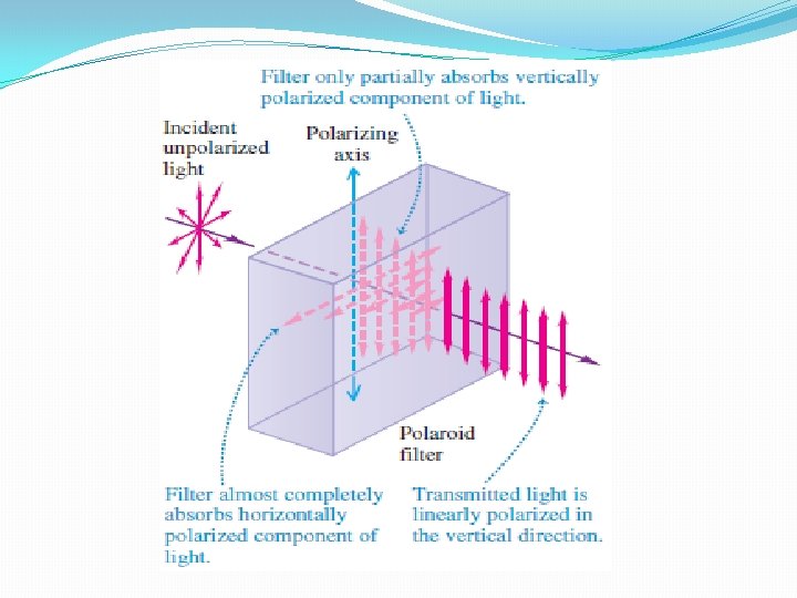
Methods of producing plane polarized light 1. 2. 3. 4. 5. Polarization by reflection Polarization by refraction Polarization by double reflection Polarization by scattering Polarization by selective absorption
Polarization by Reflection This is the simplest method to produce polarized light. According to Malus if a beam of white light is incident at one certain angle on the polished surface of a plate of ordinary glass, it is found upon reflection to be partially polarized, and the degree of polarization varies with the angle of incidence. At certain angle of incidence (≈57°) depending on the nature of the reflecting surface, the reflected light is almost plane polarized and at this angle of incidence
Brewster’s law By Snell’s law The tangent of angle of polarization is numerically equal to the refractive index of the medium.
Polarization by Refraction (A pile of plates) θp
If a beam of white light is incident upon the surface of a glass slab at the polarizing angle θp, a small fraction is reflected, which is completely polarized with the variations perpendicular to the plane of the incidence, while the rest is refracted and is only partially polarized. Of the waves vibrating perpendicular to the plane of incidence, some of energy is reflected and rest refracted for any angle of incidence. Thus the refracted ray always contain both plane of polarization. At the polarizing angle 100% (and refractive index = 1. 5) of the light vibrating parallel to the plane of incidence is transmitted, whereas for perpendicular vibrations only 85 % is transmitted, other 15% being reflected. If the ordinary light is incident at the polarizing angle on a pile of plates, some of the vibrations perpendicular to the plane of incidence are reflected at
each surface and all the those parallel to it are refracted. The net result is that the reflected beam are all plane polarized in the same plane, and the refracted beam, having lost more and more of its perpendicular vibrations, is partially plane-polarized. The larger the number of surfaces, the more nearly plane-polarized is the transmitted beam.
Malus Law This law tells us how the intensity transmitted by the analyzer varies with the angle that its plane of transmission makes with that of the polarizer. E₀ = amplitude of electric vector transmitted by the polarizer. E₀
Proof Will analyzer will transmit only the component (E₀Cosθ), which is parallel to its transmission axis. However, the component (E₀Sinθ), will be absorb by the analyzer. Therefore, the intensity transmitted by the analyzer is Cases (i) if θ = 0 or 180°, I = I₀ i. e the intensity of light transmitted by the analyzer is maximum. (ii) if θ = 90° or 180, I = 0 i. e the intensity of light transmitted by the analyzer is minimum.
Polarization by Double Refraction (Birefringence) The phenomenon in which a ray of light incident on a calcite or quartz crystal is split into two refracted rays is called double refraction. One ray obeys ordinary laws of refraction i. e. sin i /sinr is always constant for all values of angle of incidence i. This ray is called ordinary ray. The second refracted ray does not obey ordinary laws of refraction i. e. sini/sinr does not constant for all values of angle of incidence i. This ray even suffers refraction even at normal incidence. This ray is called ordinary ray.
1. The ordinary ray (O-ray) obey the laws of refraction, i. e. , it always lie in the plane of incidence and its velocity in the crystal is the same in all directions. 2. The extraordinary ray (E-ray) does not obey the laws of refraction. It travel in the crystal with different speeds in different orientations. 3. In case of ordinary ray (O-ray) the refractive is constant. 4. In case of ordinary ray (E-ray) the refractive is not constant, varies with angle of incidence. 5. For quartz crystal (uniaxial positive crystals). 6. For quartz crystal (uniaxial negative crystals).
Geometry of calcite crystal P W
A calcite crystal (Ca. Co₃) is a colorless transparent crystal to visible as well as ultraviolet light. Each face of the crystal is a parallelogram having angles 102° and 78°. At two diametrically opposite corners, P and W (called blunt corners) the angles of three faces meet there, are obtuse (>90°), while at the rest six corners, two angles are acute and remaining one is obtuse. Optic axis A line passing through one of the blunt corners and equally inclined to all the three edges meeting over there gives the direction of optic axis. Any line parallel to this line is also known as optic axis.
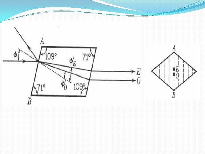
Principal section A plane containing optic axis and perpendicular to the opposite faces of the crystal is called principal section of the crystal. optic axis 109° 71°
Principal plane of the crystal The principal plane or principal section of the ordinary ray (O-ray) is defined as a plane which contain ordinary ray and optic axis. The principal plane of the extraordinary ray (E-ray) is defined as a plane which contain extraordinary ray and optic axis. Ordinarily, the ordinary and extraordinary planes do not coincide except in a case when the plane of incidence and principal section are same.
Huygen’s theory of double refraction in uniaxial crystals 1. The incident wave disturb all the points on the face of the crystal on which it is incident. Thus every point on the surface originates the two wave fronts, one the ordinary and other the extraordinary. 2. Shape of the wave front corresponding to the ordinary wavelets is spherical because of the constant velocity of O-ray in all directions. 3. Shape of the wave front corresponding to the extraordinary wavelets is ellipsoidal because E-ray has different velocities in all directions. 4. The direction of line joining these two wave fronts i. e. , sphere and ellipsoidal is the optic axis.
Nicol prism is an optical device. It is made from calcite crystal and is used in many instruments for production and analyze plane polarized light. Principle Construction of Nicol prism is based on the phenomenon of polarization by double refraction.
Construction Nicol Prism is by uniaxial negative crystal (calcite crystal), whose length is approximately three times its width i. e. , L: B = 3: 1. the end faces of the crystal are ground such that the principal section to a more acute angle for 68° instead of 71°. Then the crystal is cut into two equal halves along the diagonal and these two halves are connected together by a thin layer of Canada balsam is transparent material whose refractive index lies midway between indices of ordinary and extraordinary rays of calcite crystal.
Working optic axis Canada balsam E-ray O-ray
Working A ay of unpolarized light SM incident on one of the faces BA’ of the prism and is nearly parallel to BD’. This ray is split into E- and O- rays with perpendicular and parallel vibrations. The ordinary passing from calcite to Canada balsam travel from denser (μo = 1. 66) to rare (μcb = 1. 55) medium and is therefore, totally reflected only when the angle of incidence at Canada balsam layer is greater than a certain critical angle for the two media (calcite and Canada balsam), i. e. This totally reflected ray is, as a result, absorbed by the side BD’ of the prism and only extraordinary ray can be transmitted through this prism as it is travelling from the rare (μe= 1. 49) to denser (μcb = 1. 55) medium.
Nicol prism as an analyzer Nicol Prism can also be used as an analyzer in addition to being used as an polarizer. Plane polarized light when allowed to pass through a rotating prism indicates a variation in intensity from maximum to zero. The intensity is maximum, when Nicol prism has its plane parallel to the plane of polarization of incident light. The intensity goes to zero when the plane of polarizer is perpendicular to the plane of Nicol prism. Thus a rotating prism can be used to analyze plane polarized light.
Drawbacks 1. Nicol prism can act as polarizer only if the incident beam is slightly convergent or slightly divergent and fails, if the beam is highly convergent or divergent. 2. If the angle of incident ray So. M at crystal surface is increased, the angle of incident at Canada balsam surface decreases. If the angle SPS 0 is greater than 14°, the angle of incidence at Canada balsam surface is less than < 69° and ordinary ray is also transmitted through Nicol Prism. Hence emergent ray from Nicol prism will be mixture of O-ray and E -ray i. e. will not be plane polarized.
Drawbacks 3. 4. different directions of E-ray, being maximum when it is travelling at right angle to the optic axis and minimum when it is travelling along optic axis. travel with same speed for intermediate angles, it is between 1. 49 and 1. 66. for particular value of angle of incidence of ray Se. M , and E-ray will also be totally internally reflected and no light emerges from Nicol prism.
Plane, circularly and elliptically polarized light Plane polarized light When light travels along a certain direction, the vibrations takes place in a direction at right angle to the direction of propagation. If the vibrations are linear and takes place parallel to the plane through the axis of beam or the direction of propagation, light is said to be plane polarized.
Elliptically polarized light When the vibrations are elliptical, having a constant period and takes place in a plane perpendicular to the direction of propagation, the light is said to be elliptically polarized. In elliptical polarized light, the amplitude of vibrations changing in magnitude as well as in direction. Circularly polarized light When the vibrations are circular having a constant period and takes place in the transverse plane, the light is said to be circularly polarized light, the amplitude of vibrations remain constant but changes only the direction.
Superposition of two plane polarized light having perpendicular vibrations(circularly and elliptically polarized light) Y B O Asinθ P Optic axis A θ Acosθ E X
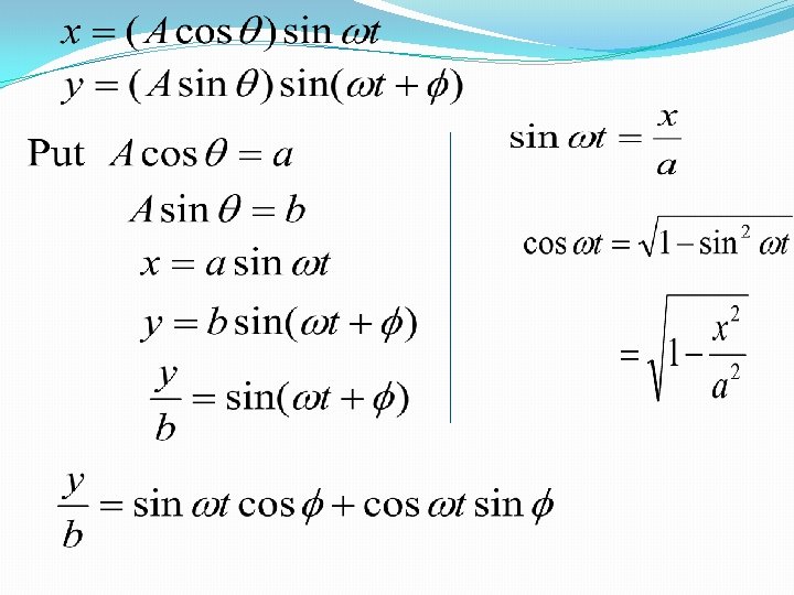
Let a plane polarized light of wave length λ and of amplitude A be incident normally on a uniaxial doubly refracting crystal whose face has been cut parallel to the optic axis. Let the vibrations of the plane polarized light be inclined beam is split up into two components, ordinary and extraordinary rays. On emerging out of the crystal, phase difference is introduced between them because of different velocities of these rays in the same direction. Let φ the phase difference between ordinary and extraordinary rays.
Let a plane polarized light of wave length λ and of amplitude A be incident normally on a uniaxial doubly refracting crystal cut with its optic axis parallel to its faces. Let the linear vibration of the plane polarized light along AB be making an angle θ with optic axis. When the plane polarized light is incident on calcite crystal, the light wave split into two perpendicular directions, AO and AE. On emerging out of the crystal, phase difference is introduced between them because of different velocities of these rays in the same direction. Let φ the phase difference between ordinary and extraordinary rays.
squaring This is the equation of an oblique ellipse
Special cases Case I. when φ = 0, 2π This is the equation of a straight line having positive slope b/a. This indicate that the resultant light is plane polarized in the same plane as the incident light.
Case II. when φ = π/4, This represents the general equation of an ellipse inclined to the axis.
Case III. when φ = π/2, 3π/2, …. . and a ≠ b Which is the equation of the ellipse with its major and minor axes coinciding with the coordinate axis. Thus, the resultant light is elliptically polarized.
Case IV. when φ = π/2, 3π/2, …. . And a = b Then the incident vibrations are inclined at angle 45° with the optical axis then equation (1) becomes Which is the equation of circle
Case V. when φ = π, 3π, …. . Then equation (1) becomes This is the equation of a straight line having negative slope b/a. This indicate that the resultant light is plane polarized. We conclude therefore that the wave progresses the phase changes, the resultant vibrations take different forms such as straight line, an ellipse and a circle (when a = b) and so on.
Phase Retardation Plates (Birefringence) An optical property in which a single ray of unpolarized light entering an anisotropic medium normally, it splits into two rays, one of which (E-ray) vibrate along optic axis and other (O-ray) vibrate perpendicular to it. Their direction of propagation will be same but they will have different velocities. Due to the difference in velocities the slow ray legs behind the fast ray which causes retardation. The magnitude of retardation depends upon the thickness (d)of the crystals.
Time taken by the slow ray(o-ray) to pass the crystal = t During the same time the fast ray (e-ray) passes through the crystal and certain additional distance known as retardation, Comparing these two equation
Here is known as birefringence and its maximum value is the characteristic of the material. Between the two mutually perpendicular coherent waves the relative phase retardation will be created. Thus the plate is known as phase retardation plate.
Half wave plates A crystal plate which can introduce a path difference of λ/2 or a path difference of π between the ordinary and extraordinary rays is called a half wave plate.
Quarter wave plates A crystal plate which can introduce a path difference of λ/4 or a path difference of π/2 between the ordinary and extraordinary rays is called a quarter wave plate.
Production of plane circularly and elliptically polarized light. (a) Plane polarized light With Nicol prism
(b) Circularly polarized light Ordinary light (unpolarized light) is first allowed to pass through a Nicol prism to convert it to plane polarized light. This PPL is then allowed to fall on quarter wave plate (QWP) at an angle of 45° with optic axis. The emergent beam from the QWP is circularly polarized obtained as a result of two polarized beams with a phase difference of 2π and of equal magnitude.
(b) Elliptically polarized light Ordinary light (unpolarized light) is first allowed to pass through a Nicol prism to convert it to plane polarized light. This PPL is then allowed to fall on quarter wave plate (QWP) at an angle which is not equal to 45°with optic axis. The emergent beam from the QWP is elliptically polarized obtained as a result of two polarized beams with a phase difference of 2π and of unequal magnitude.