ME 423 Chapter 8 PREDICTION OF PERFORMANCE OF
- Slides: 82
ME 423 Chapter 8 PREDICTION OF PERFORMANCE OF SIMPLE GAS TURBINES Prof. Dr. O. Cahit ERALP
Prediction of Performance for GT Prediction of Performance of Simple Gas Turbine • From cycle calculations it is possible to determine the PRESSURE RATIO ( Rc ) which will give the best overall efficiency for a given Tmax. • MASS FLOW RATE to give the most suitable desired power output. • After such preliminary calculations, the most suitable design data for a particular application can be chosen. • Then, it is possible to design individual components to give the required operation at the design point. • That is running at the design speed N*, mass flow rate m* and pressure ratio R*. Me 423 Spring 2006 Prof. Dr. O. Cahit ERALP
Prediction of Performance for GT Prediction of Terformance of Simple Gas Turbine • Then the off-design performance has to be determined which is the divergence from the design point over the complete operating range of speed and power output. • The performance ¢ of the individual components may be estimated on the basis of the previous experience or actual experiments. When they are combined in an engine their operating range is considerably reduced. • The problem is to find the Operating point (OP) on each component ¢ when the engine is running at a steady speed (EQUILIBRIUM). • The plot of these OP's form the EQUILIBRIUM RUNNING LINE (ERL). Me 423 Spring 2006 Prof. Dr. O. Cahit ERALP
Prediction of Performance for GT Prediction of Performance of Simple Gas Turbine • For the whole range of operating speeds, it will generate the EQUILIBRIUM RUNNING DIAGRAM. • Determining the OP; the power output, thrust and the SFC can be obtained. • The Equilibrium Running Diagram indicates the margin of operation from the surge line (SL). • This margin indicates a Margin of stability; indicates if there is enough margin to operate with adequate compressor efficiency. • If the surge line is crossed some action has to be taken to recover, not to give rise to a failure. • Ideally the engine should be operated within the region of maximum possible efficiencies. Me 423 Spring 2006 Prof. Dr. O. Cahit ERALP
Prediction of Performance for GT Prediction of Performance of Simple Gas Turbine 1. Variation of SFC with reduction in power PART LOAD PERFORMANCE. This is important while running the GT at low power settings. 2. Poor sfc at part load is the biggest disadvantage of a GT, especially a vehicular one. 3. The effect of ambient conditions on maximum output is also important, i. e. high & low Ta and Pa. 4. Peak load energy generation: 5. Europe: cold days in winter, 6. America: hot days in Summer 7. for airplanes: Runway length (safety) and 8. pay load (economics) are affected. Me 423 Spring 2006 Prof. Dr. O. Cahit ERALP
Prediction of Performance for GT Off-Design Performance of Simple GT 1. Here we will try to analyse a : a) Single shaft unit delivering shaft power. b) Free turbine engine - power turbine drives the load. c) Simple jet engine, where the useful output is from the propelling nozzle. 2. More complex arrangements - two spool engines, Turbofan & transient performance Chapter 9 3. Flow characteristics of a free turbine and propelling nozzle are similar and impose the same restrictions on the Gas Generator. 4. As a result of this several jet engines have been converted to Free Turbine Power engine for peak load electric generation, and marine applications. Me 423 Spring 2006 Prof. Dr. O. Cahit ERALP
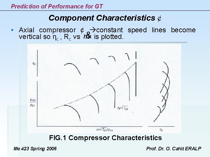
Prediction of Performance for GT Component Characteristics ¢ • Axial compressor ¢ constant speed lines become vertical so ηc , Rc vs is plotted. FIG. 1 Compressor Characteristics Me 423 Spring 2006 Prof. Dr. O. Cahit ERALP
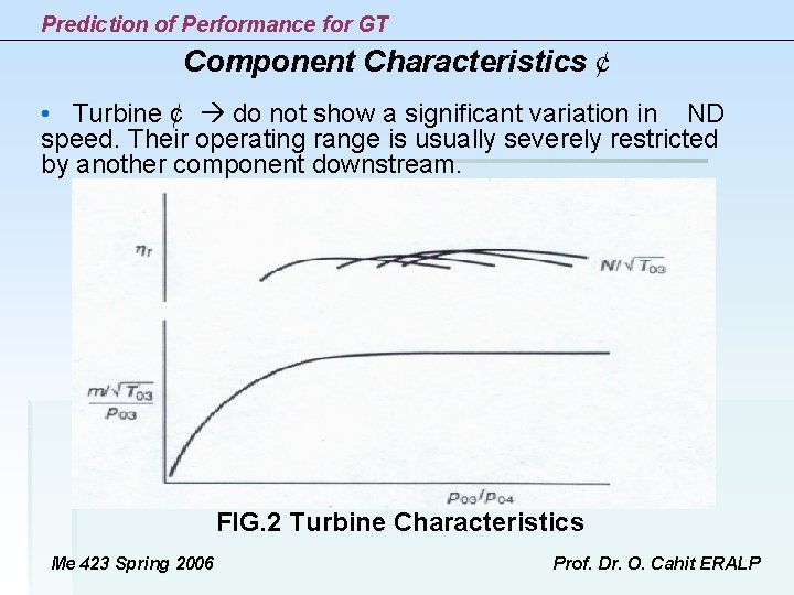
Prediction of Performance for GT Component Characteristics ¢ • Turbine ¢ do not show a significant variation in ND speed. Their operating range is usually severely restricted by another component downstream. FIG. 2 Turbine Characteristics Me 423 Spring 2006 Prof. Dr. O. Cahit ERALP
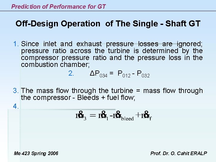
Prediction of Performance for GT Off-Design Operation of The Single - Shaft GT 1. Since inlet and exhaust pressure losses are ignored; pressure ratio across the turbine is determined by the compressor pressure ratio and the pressure loss in the combustion chamber; 2. ΔP 034 = P 012 - P 032 3. The mass flow through the turbine = mass flow through the compressor - Bleeds + fuel flow; 4. Me 423 Spring 2006 Prof. Dr. O. Cahit ERALP
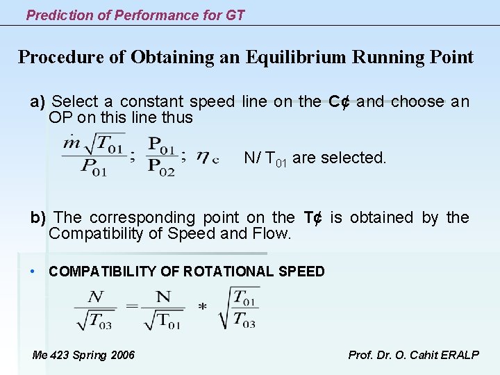
Prediction of Performance for GT Procedure of Obtaining an Equilibrium Running Point a) Select a constant speed line on the C¢ and choose an OP on this line thus N/ T 01 are selected. b) The corresponding point on the T¢ is obtained by the Compatibility of Speed and Flow. • COMPATIBILITY OF ROTATIONAL SPEED Me 423 Spring 2006 Prof. Dr. O. Cahit ERALP
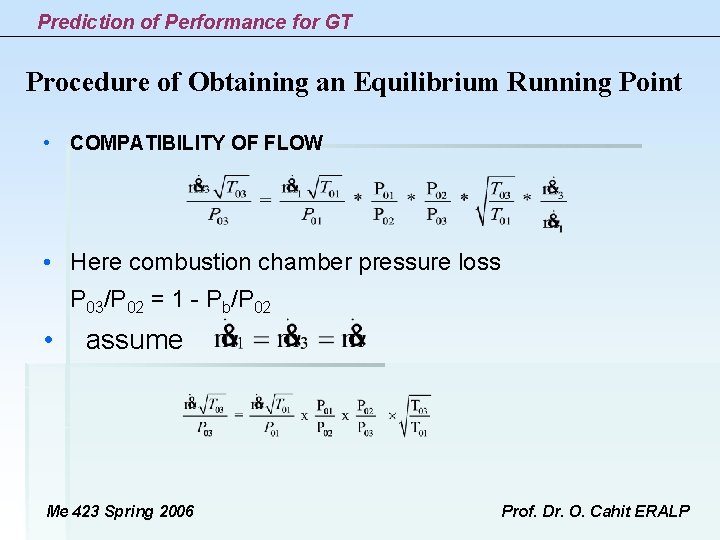
Prediction of Performance for GT Procedure of Obtaining an Equilibrium Running Point • COMPATIBILITY OF FLOW • Here combustion chamber pressure loss P 03/P 02 = 1 - Pb/P 02 • assume Me 423 Spring 2006 Prof. Dr. O. Cahit ERALP
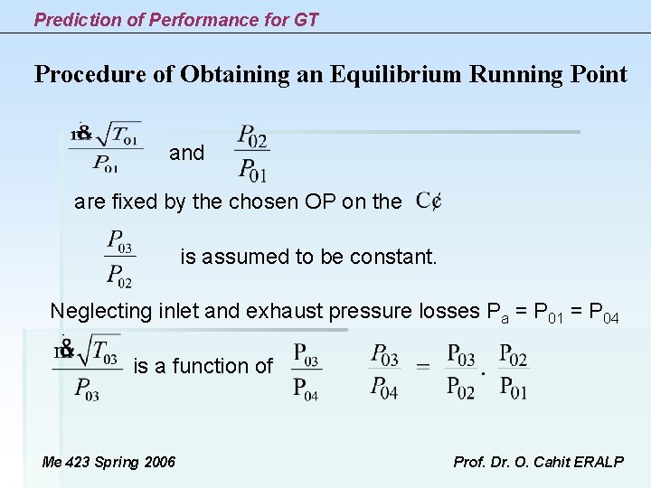
Prediction of Performance for GT Procedure of Obtaining an Equilibrium Running Point and are fixed by the chosen OP on the is assumed to be constant. Neglecting inlet and exhaust pressure losses Pa = P 01 = P 04 is a function of Me 423 Spring 2006 Prof. Dr. O. Cahit ERALP
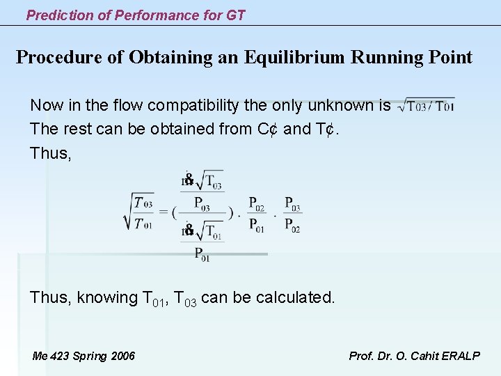
Prediction of Performance for GT Procedure of Obtaining an Equilibrium Running Point Now in the flow compatibility the only unknown is The rest can be obtained from C¢ and T¢. Thus, knowing T 01, T 03 can be calculated. Me 423 Spring 2006 Prof. Dr. O. Cahit ERALP
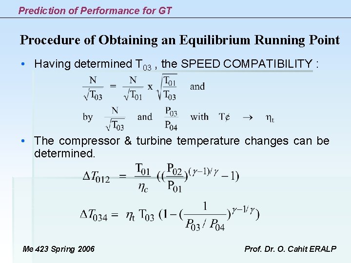
Prediction of Performance for GT Procedure of Obtaining an Equilibrium Running Point • Having determined T 03 , the SPEED COMPATIBILITY : • The compressor & turbine temperature changes can be determined. Me 423 Spring 2006 Prof. Dr. O. Cahit ERALP
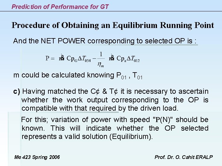
Prediction of Performance for GT Procedure of Obtaining an Equilibrium Running Point And the NET POWER corresponding to selected OP is : m could be calculated knowing P 01 , T 01 c) Having matched the C¢ & T¢ it is necessary to ascertain whether the work output corresponding to the OP is compatible with that required by the driven load. For this; variation of power with speed "P(N)" should be known. This will indicate whether the OP selected represents a valid solution (Equilibrium). Me 423 Spring 2006 Prof. Dr. O. Cahit ERALP
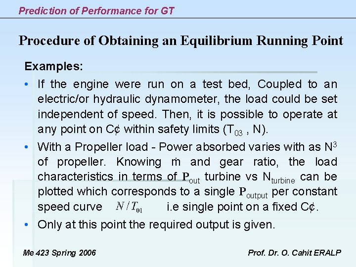
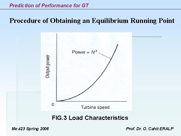
Prediction of Performance for GT Procedure of Obtaining an Equilibrium Running Point Examples: • If the engine were run on a test bed, Coupled to an electric/or hydraulic dynamometer, the load could be set independent of speed. Then, it is possible to operate at any point on C¢ within safety limits (T 03 , N). • With a Propeller load - Power absorbed varies with as N 3 of propeller. Knowing ṁ and gear ratio, the load characteristics in terms of Pout turbine vs Nturbine can be plotted which corresponds to a single Poutput per constant speed curve i. e single point on a fixed C¢. • Only at this point the required output is given. Me 423 Spring 2006 Prof. Dr. O. Cahit ERALP
Prediction of Performance for GT Procedure of Obtaining an Equilibrium Running Point FIG. 3 Load Characteristics Me 423 Spring 2006 Prof. Dr. O. Cahit ERALP
Prediction of Performance for GT Procedure of Obtaining an Equilibrium Running Point • Then the single point on each constant speed line of the C¢ has to be found. • This is done by trial error, taking several OP on the C¢ and establishing the power output for each OP. • If the power output by turbine is not equal to power required by propeller then the engine will not be in equilibrium but accelerate or decelerate. • Finding the equilibrium points on a series of constant speed lines, and joining them the equilibrium running line is obtained. • The most common type of load used with a single shaft GT is the ELECTRIC GENERATOR which runs at constant N with the electrical load varying. Me 423 Spring 2006 Prof. Dr. O. Cahit ERALP
Prediction of Performance for GT Procedure of Obtaining an Equilibrium Running Point • Then the single point on each constant speed line of the C¢ has to be found. • This is done by trial error, taking several OP on the C¢ and establishing the power output for each OP. • If the power output by turbine is not equal to power required by propeller then the engine will not be in equilibrium but accelerate or decelerate. • Finding the equilibrium points on a series of constant speed lines, and joining them the equilibrium running line is obtained. • The most common type of load used with a single shaft GT is the ELECTRIC GENERATOR which runs at constant N with the electrical load varying. Me 423 Spring 2006 Prof. Dr. O. Cahit ERALP
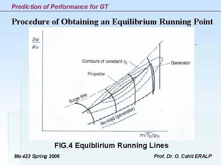
Prediction of Performance for GT Procedure of Obtaining an Equilibrium Running Point FIG. 4 Equiblirium Running Lines Me 423 Spring 2006 Prof. Dr. O. Cahit ERALP
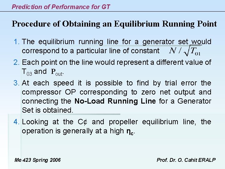
Prediction of Performance for GT Procedure of Obtaining an Equilibrium Running Point 1. The equilibrium running line for a generator set would correspond to a particular line of constant 2. Each point on the line would represent a different value of T 03 and Pout. 3. At each speed it is possible to find by trial error the compressor OP corresponding to zero net output and connecting the No-Load Running Line for a Generator Set is obtained. 4. Looking at the C¢ and propeller equilibrium line, the operation is generally at a high ηc. Me 423 Spring 2006 Prof. Dr. O. Cahit ERALP
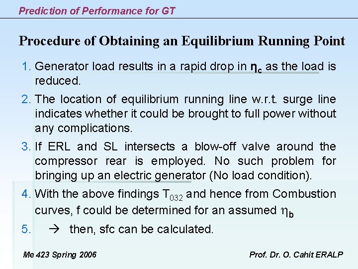
Prediction of Performance for GT Procedure of Obtaining an Equilibrium Running Point 1. Generator load results in a rapid drop in ηc as the load is reduced. 2. The location of equilibrium running line w. r. t. surge line indicates whether it could be brought to full power without any complications. 3. If ERL and SL intersects a blow-off valve around the compressor rear is employed. No such problem for bringing up an electric generator (No load condition). 4. With the above findings T 032 and hence from Combustion curves, f could be determined for an assumed b 5. then, sfc can be calculated. Me 423 Spring 2006 Prof. Dr. O. Cahit ERALP
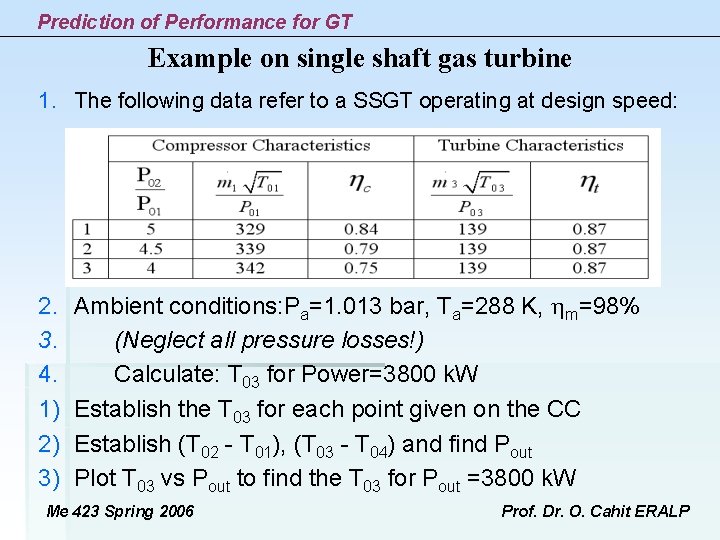
Prediction of Performance for GT Example on single shaft gas turbine 1. The following data refer to a SSGT operating at design speed: 2. 3. 4. 1) 2) 3) Ambient conditions: Pa=1. 013 bar, Ta=288 K, m=98% (Neglect all pressure losses!) Calculate: T 03 for Power=3800 k. W Establish the T 03 for each point given on the CC Establish (T 02 - T 01), (T 03 - T 04) and find Pout Plot T 03 vs Pout to find the T 03 for Pout =3800 k. W Me 423 Spring 2006 Prof. Dr. O. Cahit ERALP
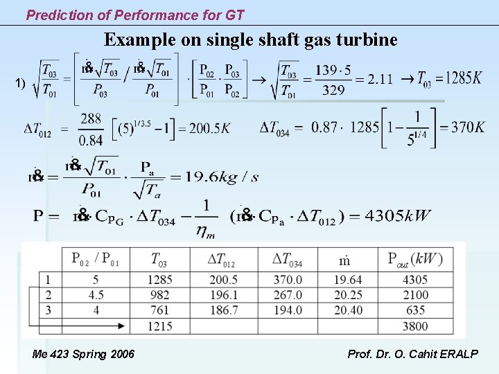
Prediction of Performance for GT Example on single shaft gas turbine 1) Me 423 Spring 2006 Prof. Dr. O. Cahit ERALP
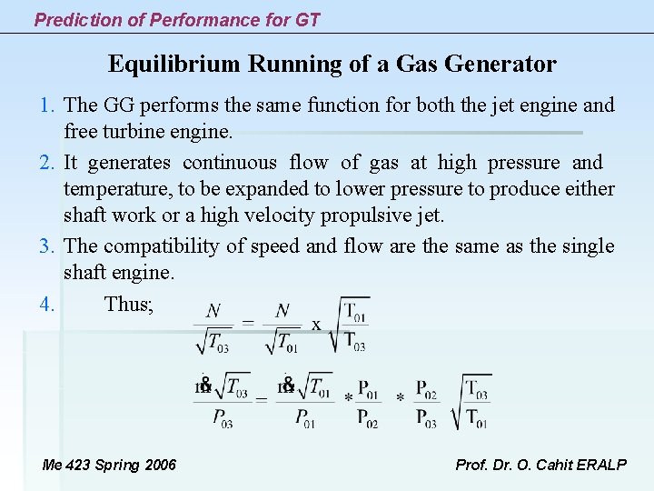
Prediction of Performance for GT Equilibrium Running of a Gas Generator 1. The GG performs the same function for both the jet engine and free turbine engine. 2. It generates continuous flow of gas at high pressure and temperature, to be expanded to lower pressure to produce either shaft work or a high velocity propulsive jet. 3. The compatibility of speed and flow are the same as the single shaft engine. 4. Thus; Me 423 Spring 2006 Prof. Dr. O. Cahit ERALP
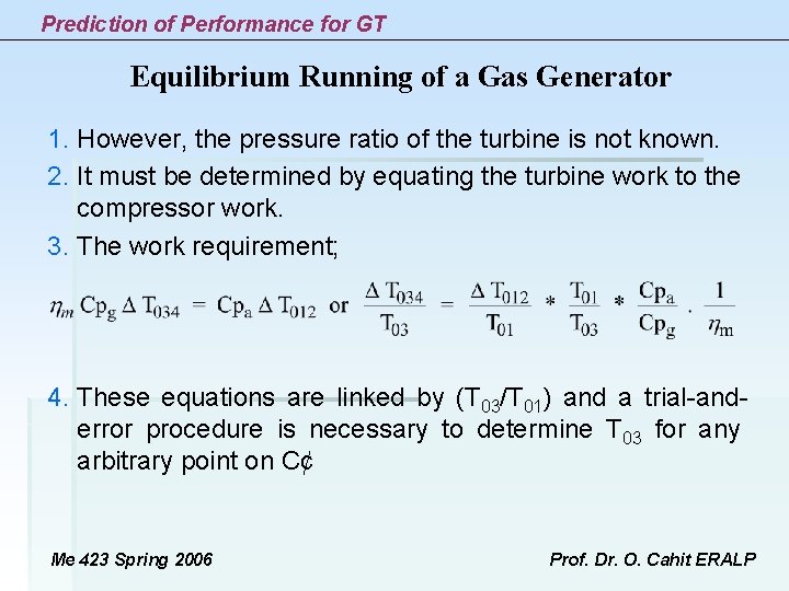
Prediction of Performance for GT Equilibrium Running of a Gas Generator 1. However, the pressure ratio of the turbine is not known. 2. It must be determined by equating the turbine work to the compressor work. 3. The work requirement; 4. These equations are linked by (T 03/T 01) and a trial-anderror procedure is necessary to determine T 03 for any arbitrary point on C¢ Me 423 Spring 2006 Prof. Dr. O. Cahit ERALP
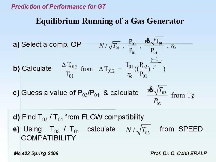
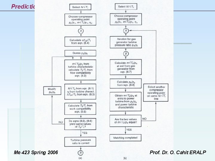
Prediction of Performance for GT Equilibrium Running of a Gas Generator a) Select a comp. OP b) Calculate c) Guess a value of P 03/P 01 & calculate d) Find T 03 / T 01 from FLOW compatibility e) Using T 03 / T 01 calculate from SPEED COMPATIBILITY Me 423 Spring 2006 Prof. Dr. O. Cahit ERALP
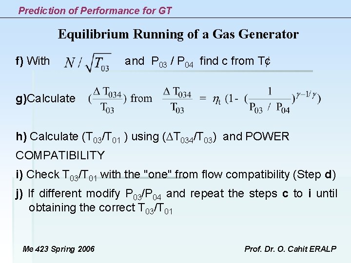
Prediction of Performance for GT Equilibrium Running of a Gas Generator f) With and P 03 / P 04 find c from T¢ g)Calculate h) Calculate (T 03/T 01 ) using ( T 034/T 03) and POWER COMPATIBILITY i) Check T 03/T 01 with the "one" from flow compatibility (Step d) j) If different modify P 03/P 04 and repeat the steps c to i until obtaining the correct T 03/T 01 Me 423 Spring 2006 Prof. Dr. O. Cahit ERALP
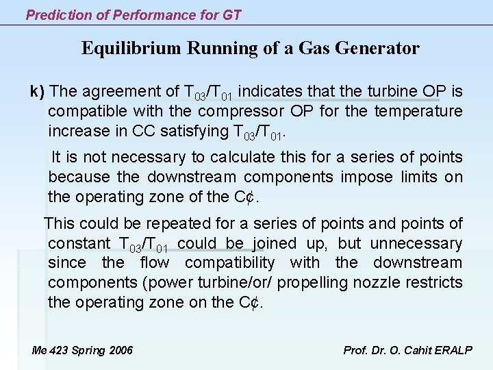
Prediction of Performance for GT Equilibrium Running of a Gas Generator k) The agreement of T 03/T 01 indicates that the turbine OP is compatible with the compressor OP for the temperature increase in CC satisfying T 03/T 01. It is not necessary to calculate this for a series of points because the downstream components impose limits on the operating zone of the C¢. This could be repeated for a series of points and points of constant T 03/T 01 could be joined up, but unnecessary since the flow compatibility with the downstream components (power turbine/or/ propelling nozzle restricts the operating zone on the C¢. Me 423 Spring 2006 Prof. Dr. O. Cahit ERALP
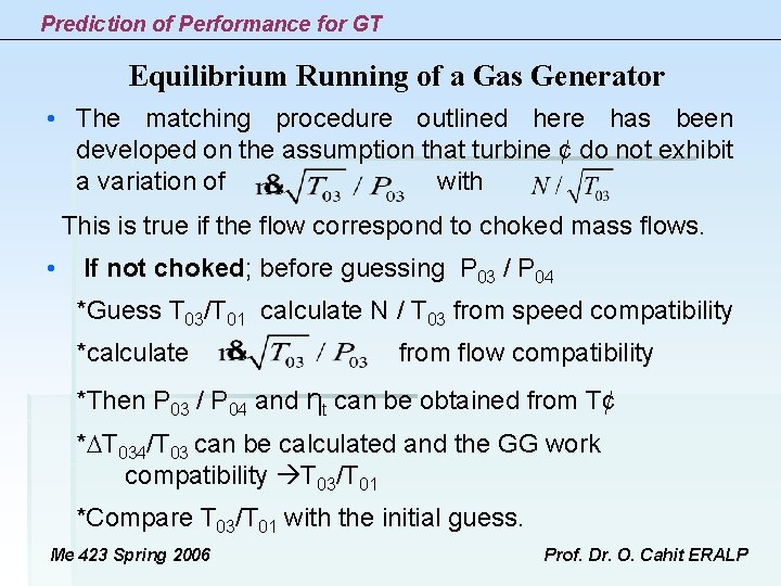
Prediction of Performance for GT Equilibrium Running of a Gas Generator • The matching procedure outlined here has been developed on the assumption that turbine ¢ do not exhibit a variation of with This is true if the flow correspond to choked mass flows. • If not choked; before guessing P 03 / P 04 *Guess T 03/T 01 calculate N / T 03 from speed compatibility *calculate from flow compatibility *Then P 03 / P 04 and ηt can be obtained from T¢ * T 034/T 03 can be calculated and the GG work compatibility T 03/T 01 *Compare T 03/T 01 with the initial guess. Me 423 Spring 2006 Prof. Dr. O. Cahit ERALP
Prediction of Performance for GT Me 423 Spring 2006 Prof. Dr. O. Cahit ERALP
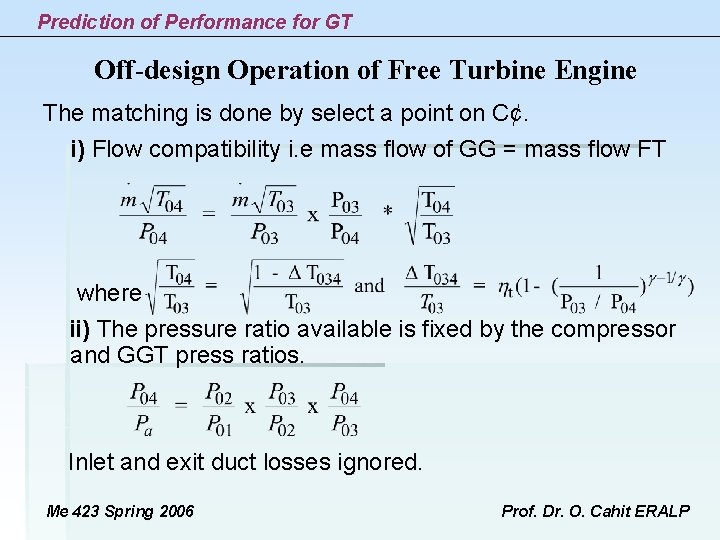
Prediction of Performance for GT Off-design Operation of Free Turbine Engine The matching is done by select a point on C¢. i) Flow compatibility i. e mass flow of GG = mass flow FT where ii) The pressure ratio available is fixed by the compressor and GGT press ratios. Inlet and exit duct losses ignored. Me 423 Spring 2006 Prof. Dr. O. Cahit ERALP
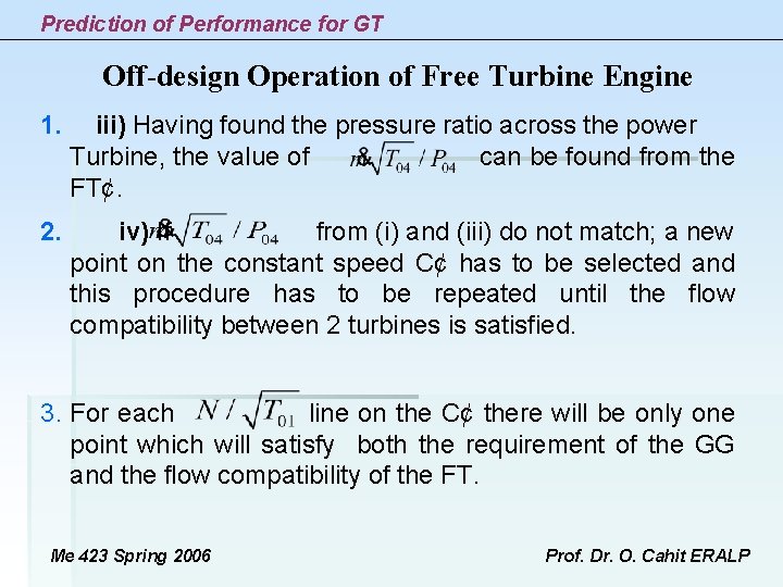
Prediction of Performance for GT Off-design Operation of Free Turbine Engine 1. iii) Having found the pressure ratio across the power Turbine, the value of can be found from the FT¢ . 2. iv) If from (i) and (iii) do not match; a new point on the constant speed C¢ has to be selected and this procedure has to be repeated until the flow compatibility between 2 turbines is satisfied. 3. For each line on the C¢ there will be only one point which will satisfy both the requirement of the GG and the flow compatibility of the FT. Me 423 Spring 2006 Prof. Dr. O. Cahit ERALP
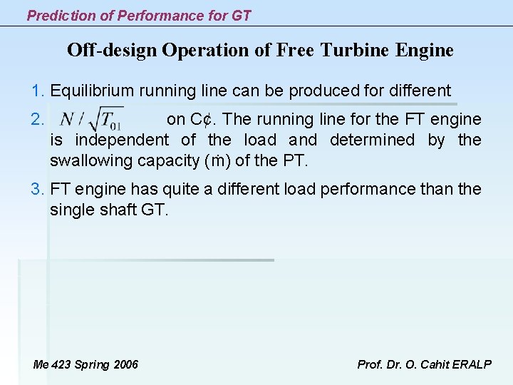
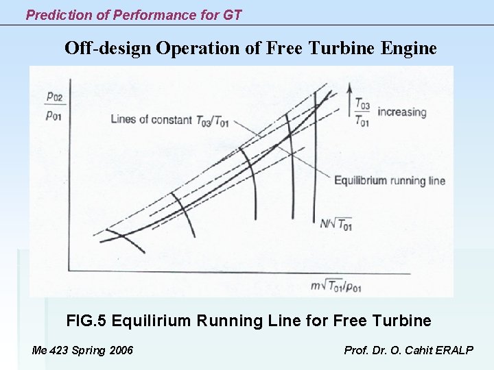
Prediction of Performance for GT Off-design Operation of Free Turbine Engine 1. Equilibrium running line can be produced for different 2. on C¢. The running line for the FT engine is independent of the load and determined by the swallowing capacity (ṁ) of the PT. 3. FT engine has quite a different load performance than the single shaft GT. Me 423 Spring 2006 Prof. Dr. O. Cahit ERALP
Prediction of Performance for GT Off-design Operation of Free Turbine Engine FIG. 5 Equilirium Running Line for Free Turbine Me 423 Spring 2006 Prof. Dr. O. Cahit ERALP
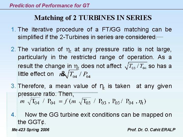
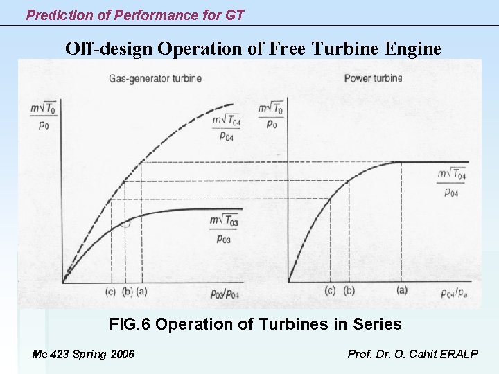
Prediction of Performance for GT Matching of 2 TURBINES IN SERIES 1. The iterative procedure of a FT/GG matching can be simplified if the 2 -Turbines in series are considered. 2. The variation of t at any pressure ratio is not large, particularly in the restricted range of operation. As a result the change in t does not affect so has a little effect on 3. Therefore, a mean value of ηt is taken at any given pressure ratio. Then, 4. Now the GG turbine exit conditions can be mapped on the GGT¢. Me 423 Spring 2006 Prof. Dr. O. Cahit ERALP
Prediction of Performance for GT Off-design Operation of Free Turbine Engine FIG. 6 Operation of Turbines in Series Me 423 Spring 2006 Prof. Dr. O. Cahit ERALP
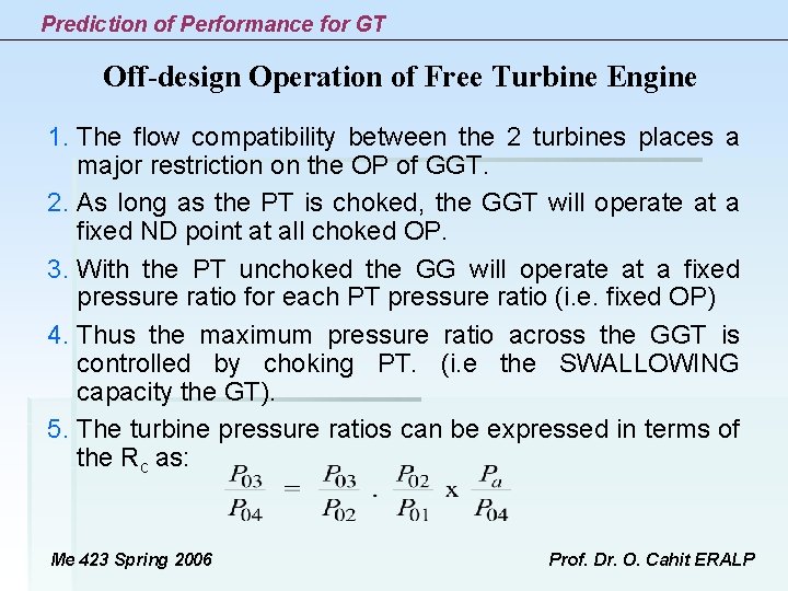
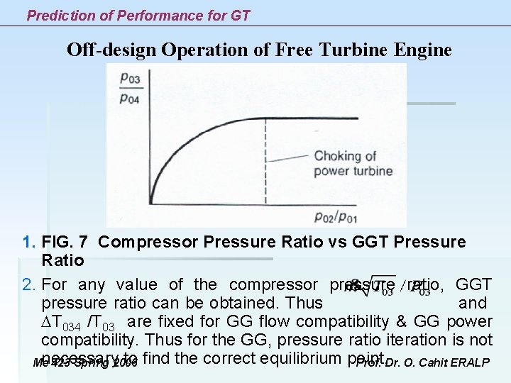
Prediction of Performance for GT Off-design Operation of Free Turbine Engine 1. The flow compatibility between the 2 turbines places a major restriction on the OP of GGT. 2. As long as the PT is choked, the GGT will operate at a fixed ND point at all choked OP. 3. With the PT unchoked the GG will operate at a fixed pressure ratio for each PT pressure ratio (i. e. fixed OP) 4. Thus the maximum pressure ratio across the GGT is controlled by choking PT. (i. e the SWALLOWING capacity the GT). 5. The turbine pressure ratios can be expressed in terms of the Rc as: Me 423 Spring 2006 Prof. Dr. O. Cahit ERALP
Prediction of Performance for GT Off-design Operation of Free Turbine Engine 1. FIG. 7 Compressor Pressure Ratio vs GGT Pressure Ratio 2. For any value of the compressor pressure ratio, GGT pressure ratio can be obtained. Thus and T 034 /T 03 are fixed for GG flow compatibility & GG power compatibility. Thus for the GG, pressure ratio iteration is not necessary to find the correct equilibrium point. Me 423 Spring 2006 Prof. Dr. O. Cahit ERALP
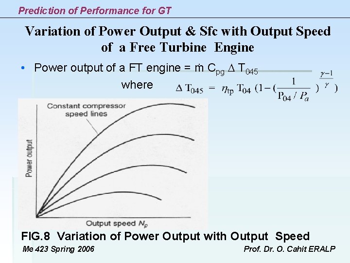
Prediction of Performance for GT Variation of Power Output & Sfc with Output Speed of a Free Turbine Engine • Power output of a FT engine = ṁ Cpg T 045 where FIG. 8 Variation of Power Output with Output Speed Me 423 Spring 2006 Prof. Dr. O. Cahit ERALP
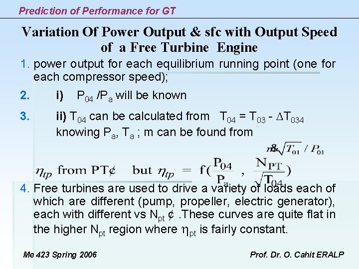
Prediction of Performance for GT Variation Of Power Output & sfc with Output Speed of a Free Turbine Engine 1. power output for each equilibrium running point (one for each compressor speed); 2. i) P 04 /Pa will be known 3. ii) T 04 can be calculated from T 04 = T 03 - T 034 knowing Pa, Ta ; m can be found from 4. Free turbines are used to drive a variety of loads each of which are different (pump, propeller, electric generator), each with different vs Npt ¢. These curves are quite flat in the higher Npt region where pt is fairly constant. Me 423 Spring 2006 Prof. Dr. O. Cahit ERALP
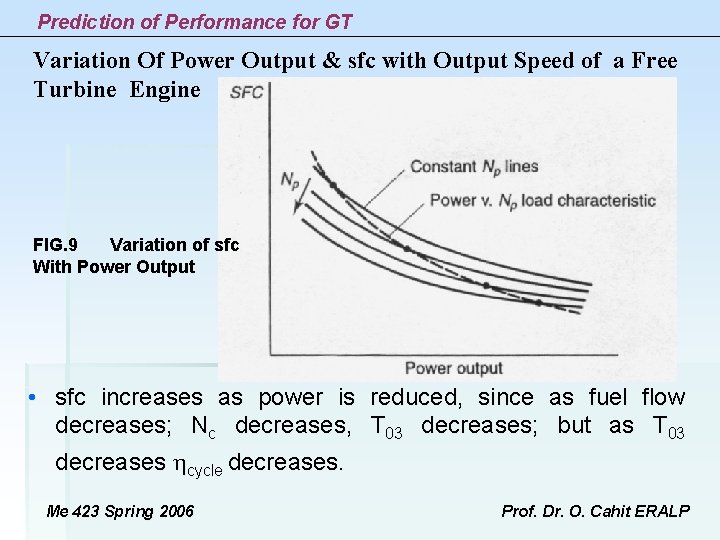
Prediction of Performance for GT Variation Of Power Output & sfc with Output Speed of a Free Turbine Engine FIG. 9 Variation of sfc With Power Output • sfc increases as power is reduced, since as fuel flow decreases; Nc decreases, T 03 decreases; but as T 03 decreases cycle decreases. Me 423 Spring 2006 Prof. Dr. O. Cahit ERALP
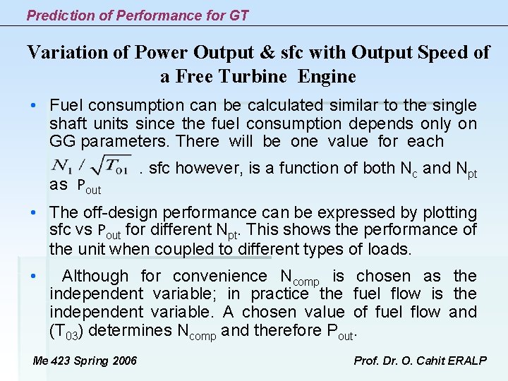
Prediction of Performance for GT Variation of Power Output & sfc with Output Speed of a Free Turbine Engine • Fuel consumption can be calculated similar to the single shaft units since the fuel consumption depends only on GG parameters. There will be one value for each . sfc however, is a function of both Nc and Npt as Pout • The off-design performance can be expressed by plotting sfc vs Pout for different Npt. This shows the performance of the unit when coupled to different types of loads. • Although for convenience Ncomp is chosen as the independent variable; in practice the fuel flow is the independent variable. A chosen value of fuel flow and (T 03) determines Ncomp and therefore Pout. Me 423 Spring 2006 Prof. Dr. O. Cahit ERALP
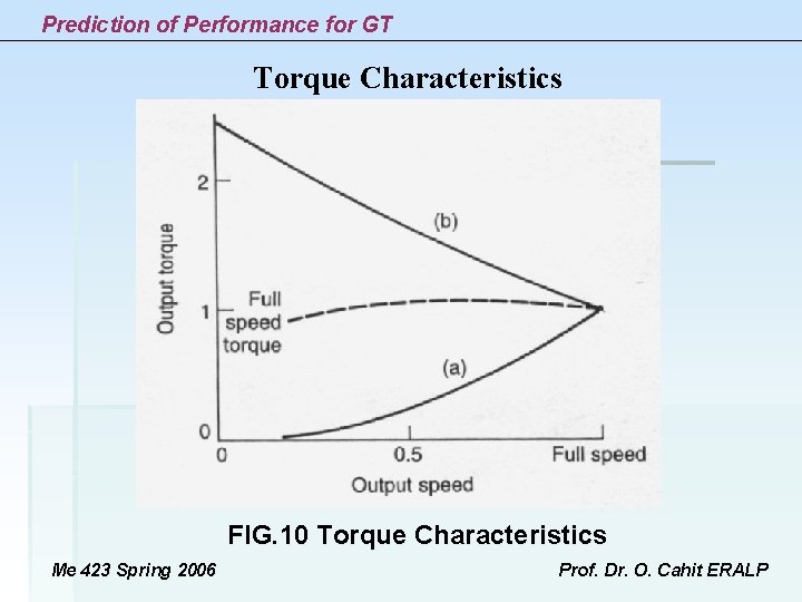
Prediction of Performance for GT Torque Characteristics • In case of a GT delivering shaft power, the variation of torque with output speed at a given power determines its suitability for different applications (e. g. high starting torque for traction). a) For the single shaft engine the compressor is constrained to turn at some multiple of load speed. Load speed decrease = Compressor speed decrease unsuitable for traction (since m decrease out decrease) b) Normal curve of Internal Combustion Engine is flat. c) Free power turbine has a favourable torque ¢ over a wide load-speed range for a fixed Nc. This is because the compressor can supply an essentially constant flow at a given compressor speed irrespective of the FT speed. Me 423 Spring 2006 Prof. Dr. O. Cahit ERALP
Prediction of Performance for GT Torque Characteristics 1. Therefore, 2. at constant Pout as Npt decrease t increase. 3. The torque might stall at high t or very low Npt. 4. With a reduction in Npt quite a large increase in t can be obtained efficiently. 5. But at least a speed gear box have to be used for traction (usually 5 -6 speed automatic transmission is used in heavy load vehicles) Me 423 Spring 2006 Prof. Dr. O. Cahit ERALP
Prediction of Performance for GT Torque Characteristics FIG. 10 Torque Characteristics Me 423 Spring 2006 Prof. Dr. O. Cahit ERALP
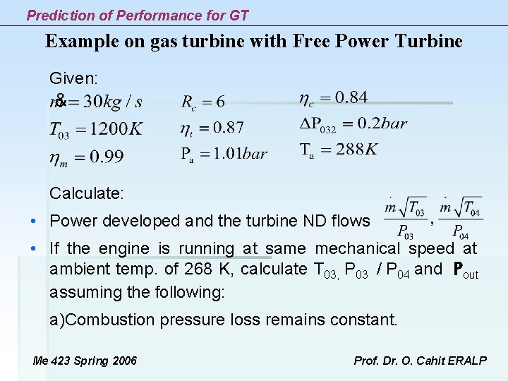
Prediction of Performance for GT Example on gas turbine with Free Power Turbine Given: Calculate: • Power developed and the turbine ND flows • If the engine is running at same mechanical speed at ambient temp. of 268 K, calculate T 03, P 03 / P 04 and Pout assuming the following: a)Combustion pressure loss remains constant. Me 423 Spring 2006 Prof. Dr. O. Cahit ERALP
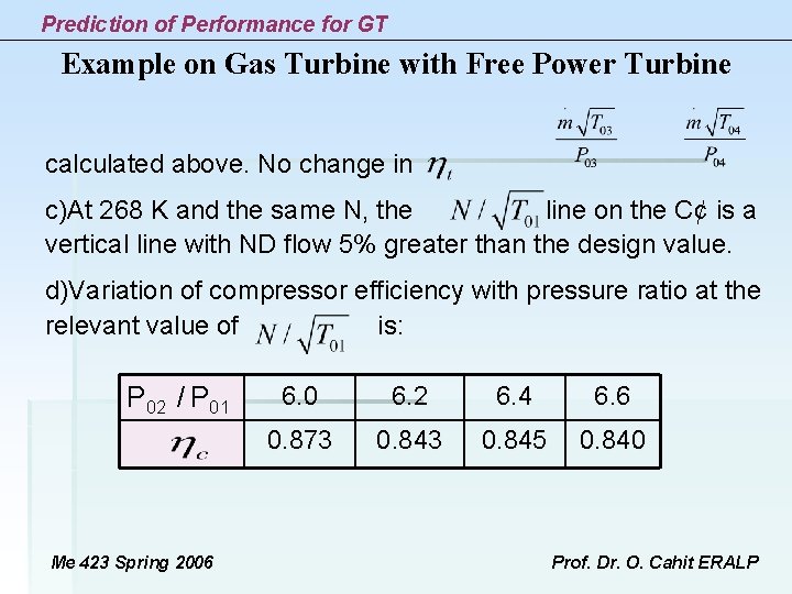
Prediction of Performance for GT Example on Gas Turbine with Free Power Turbine calculated above. No change in c)At 268 K and the same N, the line on the C¢ is a vertical line with ND flow 5% greater than the design value. d)Variation of compressor efficiency with pressure ratio at the relevant value of is: P 02 / P 01 Me 423 Spring 2006 6. 0 6. 2 6. 4 6. 6 0. 873 0. 845 0. 840 Prof. Dr. O. Cahit ERALP
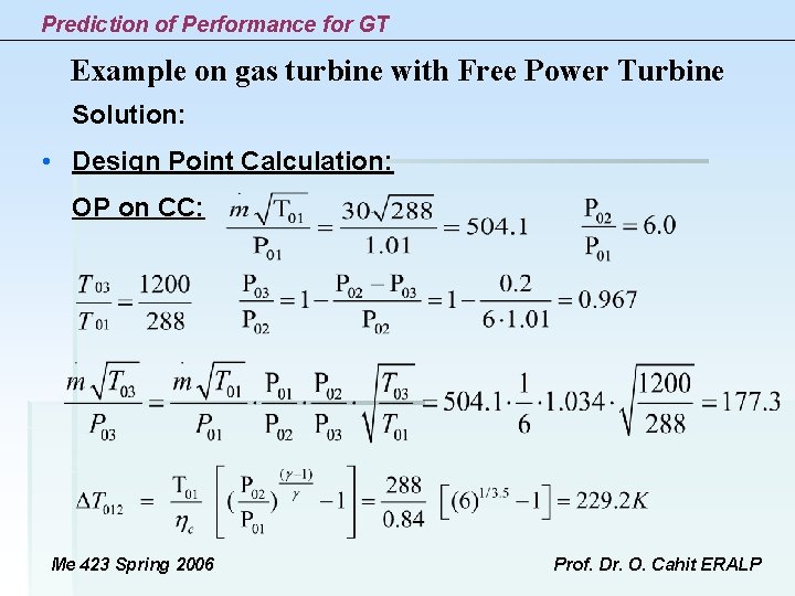
Prediction of Performance for GT Example on gas turbine with Free Power Turbine Solution: • Design Point Calculation: OP on CC: Me 423 Spring 2006 Prof. Dr. O. Cahit ERALP
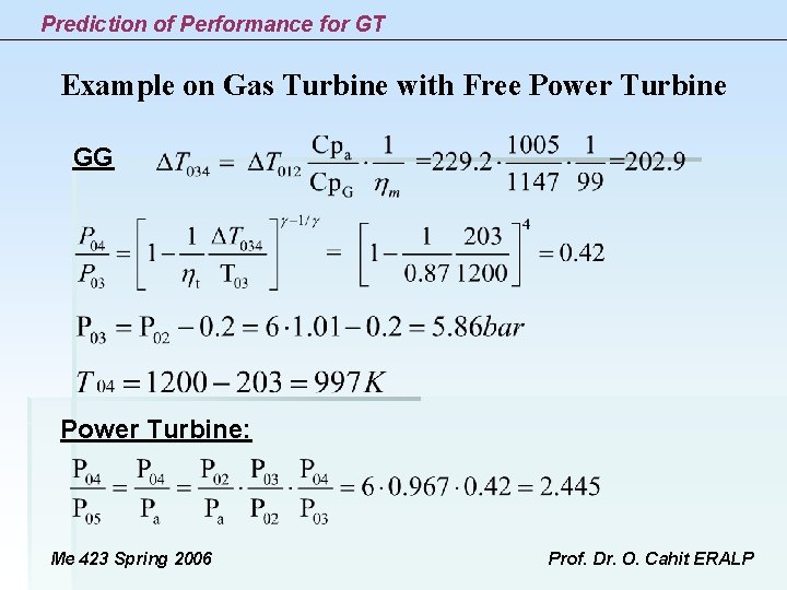
Prediction of Performance for GT Example on Gas Turbine with Free Power Turbine GG Power Turbine: Me 423 Spring 2006 Prof. Dr. O. Cahit ERALP
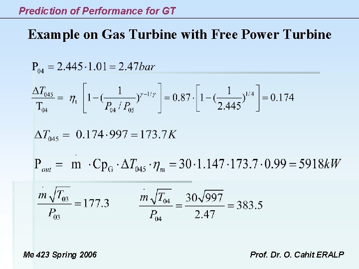
Prediction of Performance for GT Example on Gas Turbine with Free Power Turbine Me 423 Spring 2006 Prof. Dr. O. Cahit ERALP
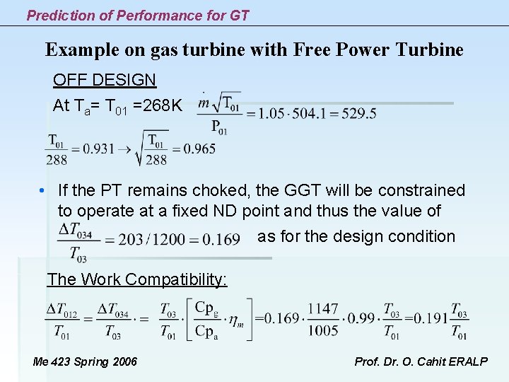
Prediction of Performance for GT Example on gas turbine with Free Power Turbine OFF DESIGN At Ta= T 01 =268 K • If the PT remains choked, the GGT will be constrained to operate at a fixed ND point and thus the value of as for the design condition The Work Compatibility: Me 423 Spring 2006 Prof. Dr. O. Cahit ERALP
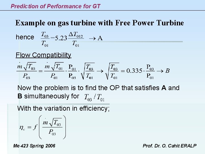
Prediction of Performance for GT Example on gas turbine with Free Power Turbine hence Flow Compatibility Now the problem is to find the OP that satisfies A and B simultaneously for With the variation in efficiency; Me 423 Spring 2006 Prof. Dr. O. Cahit ERALP
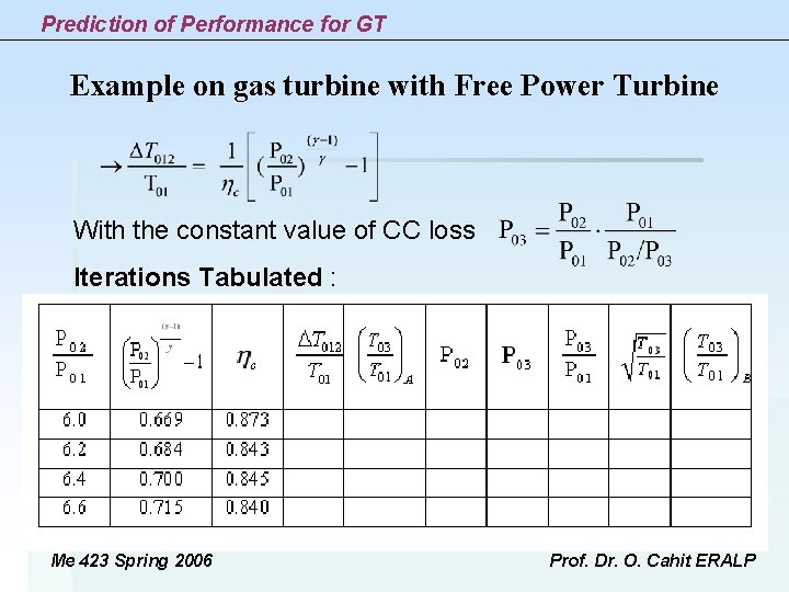
Prediction of Performance for GT Example on gas turbine with Free Power Turbine With the constant value of CC loss Iterations Tabulated : Me 423 Spring 2006 Prof. Dr. O. Cahit ERALP
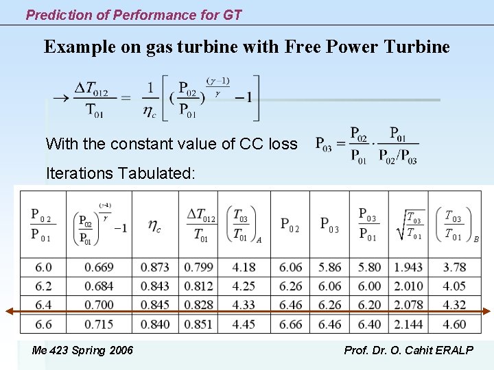
Prediction of Performance for GT Example on gas turbine with Free Power Turbine With the constant value of CC loss Iterations Tabulated: Me 423 Spring 2006 Prof. Dr. O. Cahit ERALP
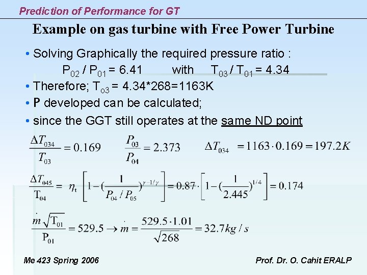
Prediction of Performance for GT Example on gas turbine with Free Power Turbine • Solving Graphically the required pressure ratio : P 02 / P 01 = 6. 41 with T 03 / T 01 = 4. 34 • Therefore ; To 3 = 4. 34*268=1163 K • P developed can be calculated; • since the GGT still operates at the same ND point Me 423 Spring 2006 Prof. Dr. O. Cahit ERALP
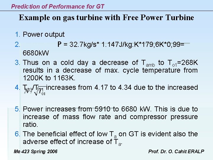
Prediction of Performance for GT Example on gas turbine with Free Power Turbine 1. Power output 2. P = 32. 7 kg/s* 1. 147 J/kg. K*179, 6 K*0, 99= 6680 k. W 3. Thus on a cold day a decrease of Tamb to To 1=268 K results in a decrease of max. cycle temperature from 1200 K to 1163 K. 4. T 03/T 01 increases from 4. 17 to 4. 34 due to the increased 5. Power increases from 5910 to 6680 k. W. This is due to increase of mass flow rate and compressor pressure ratio. 6. The beneficial effect of low Ta on GT is evident also the adverse effect of increase of Ta. Me 423 Spring 2006 Prof. Dr. O. Cahit ERALP
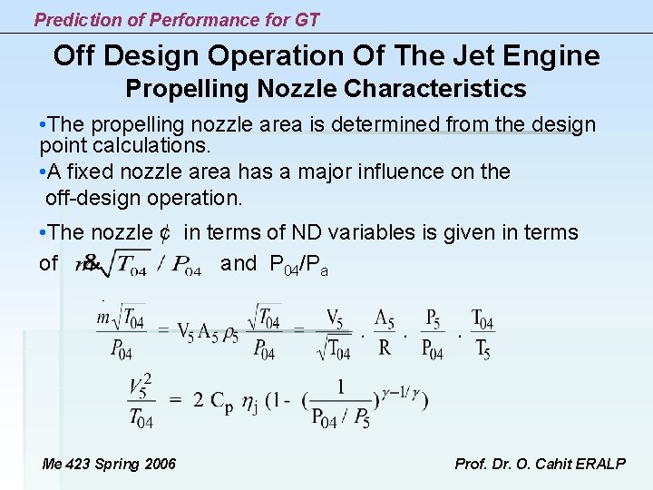
Prediction of Performance for GT Off Design Operation Of The Jet Engine Propelling Nozzle Characteristics • The propelling nozzle area is determined from the design point calculations. • A fixed nozzle area has a major influence on the off-design operation. • The nozzle ¢ in terms of ND variables is given in terms of and P 04/Pa Me 423 Spring 2006 Prof. Dr. O. Cahit ERALP
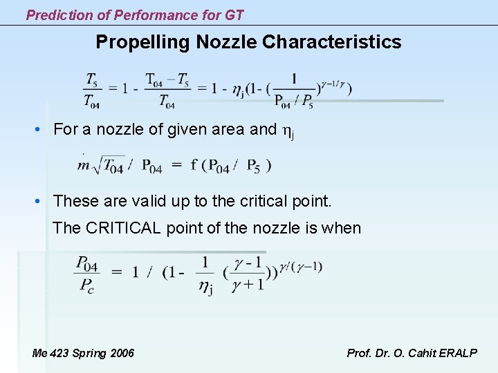
Prediction of Performance for GT Propelling Nozzle Characteristics • For a nozzle of given area and j • These are valid up to the critical point. The CRITICAL point of the nozzle is when Me 423 Spring 2006 Prof. Dr. O. Cahit ERALP
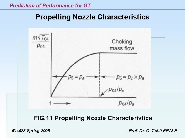
Prediction of Performance for GT Propelling Nozzle Characteristics FIG. 11 Propelling Nozzle Characteristics Me 423 Spring 2006 Prof. Dr. O. Cahit ERALP
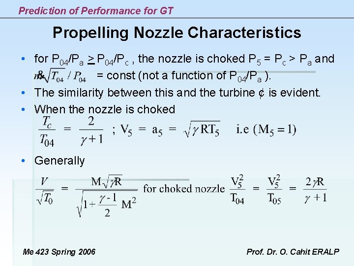
Prediction of Performance for GT Propelling Nozzle Characteristics • for P 04/Pa > P 04/Pc , the nozzle is choked P 5 = Pc > Pa and = const (not a function of P 04/Pa ). • The similarity between this and the turbine ¢ is evident. • When the nozzle is choked • Generally Me 423 Spring 2006 Prof. Dr. O. Cahit ERALP
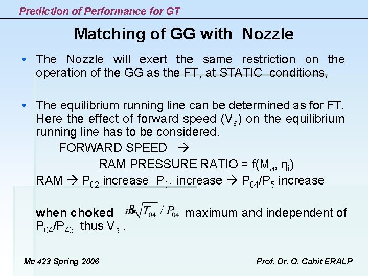
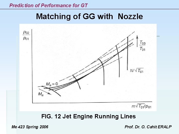
Prediction of Performance for GT Matching of GG with Nozzle • The Nozzle will exert the same restriction on the operation of the GG as the FT, at STATIC conditions, • The equilibrium running line can be determined as for FT. Here the effect of forward speed (Va) on the equilibrium running line has to be considered. FORWARD SPEED RAM PRESSURE RATIO = f(Ma, ηi) RAM P 02 increase P 04 increase P 04/P 5 increase when choked maximum and independent of P 04/P 45 thus Va. Me 423 Spring 2006 Prof. Dr. O. Cahit ERALP
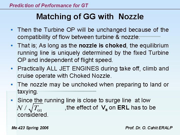
Prediction of Performance for GT Matching of GG with Nozzle • Then the Turbine OP will be unchanged because of the compatibility of flow between turbine & nozzle. is; As long as the nozzle is choked, the equilibrium • That running line is uniquely determined by the fixed Turbine OP and independent of flight speed. • Practically ALL JET ENGINES during take off, climb and cruise operate with Choked Nozzle. • The nozzle may be unchoked when preparing to land or taxying. • Since the running line is close to surge line at low , the effect of Va on ERL has to be considered. Me 423 Spring 2006 Prof. Dr. O. Cahit ERALP
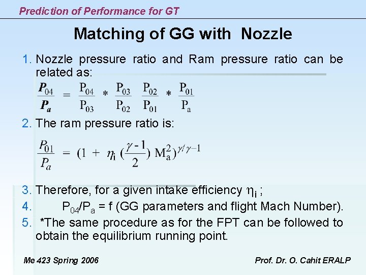
Prediction of Performance for GT Matching of GG with Nozzle 1. Nozzle pressure ratio and Ram pressure ratio can be related as: 2. The ram pressure ratio is: 3. Therefore, for a given intake efficiency i ; 4. P 04/Pa = f (GG parameters and flight Mach Number). 5. *The same procedure as for the FPT can be followed to obtain the equilibrium running point. Me 423 Spring 2006 Prof. Dr. O. Cahit ERALP
Prediction of Performance for GT Matching of GG with Nozzle FIG. 12 Jet Engine Running Lines Me 423 Spring 2006 Prof. Dr. O. Cahit ERALP
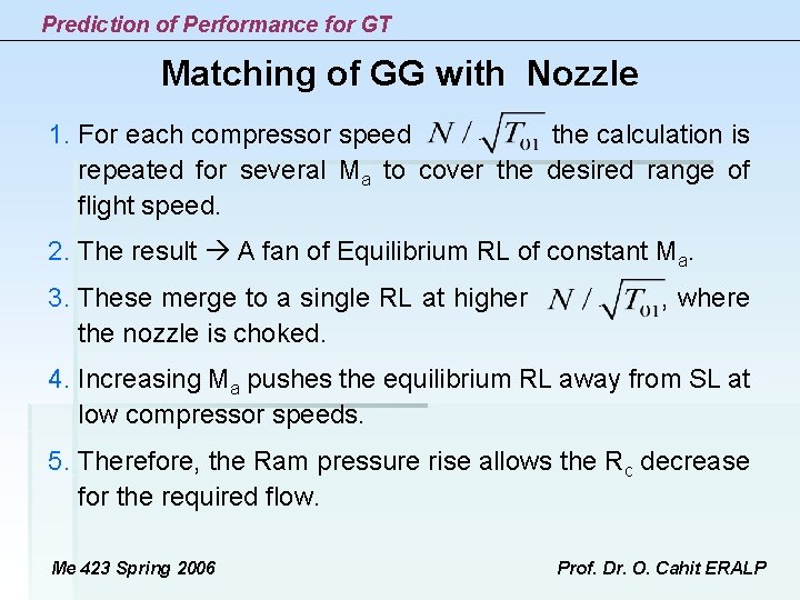
Prediction of Performance for GT Matching of GG with Nozzle 1. For each compressor speed the calculation is repeated for several Ma to cover the desired range of flight speed. 2. The result A fan of Equilibrium RL of constant Ma. 3. These merge to a single RL at higher , where the nozzle is choked. 4. Increasing Ma pushes the equilibrium RL away from SL at low compressor speeds. 5. Therefore, the Ram pressure rise allows the Rc decrease for the required flow. Me 423 Spring 2006 Prof. Dr. O. Cahit ERALP
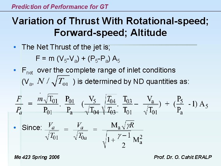
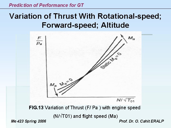
Prediction of Performance for GT Variation of Thrust With Rotational-speed; Forward-speed; Altitude • The Net Thrust of the jet is; F = m (V 5 -Va) + (P 5 -Pa) A 5 • Fnet over the complete range of inlet conditions (Va, ) is determined by ND quantities as: • Since: Me 423 Spring 2006 Prof. Dr. O. Cahit ERALP
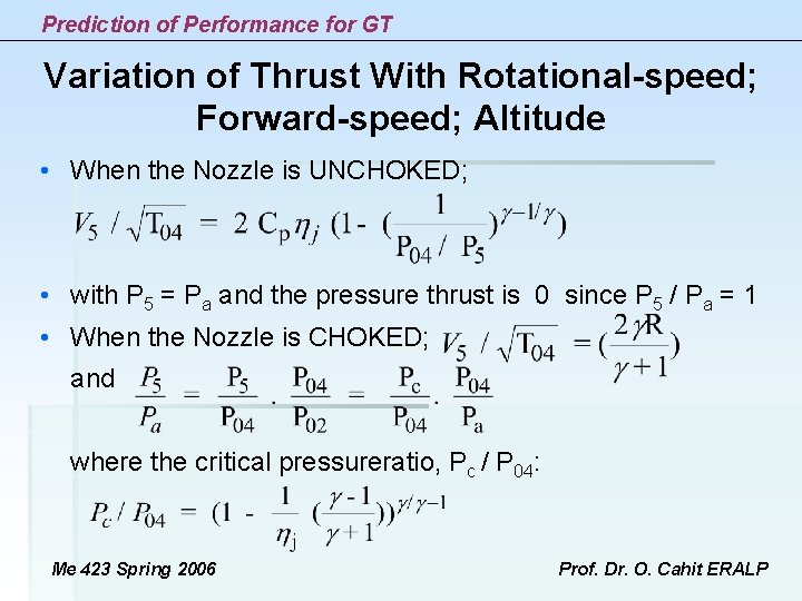
Prediction of Performance for GT Variation of Thrust With Rotational-speed; Forward-speed; Altitude • When the Nozzle is UNCHOKED; • with P 5 = Pa and the pressure thrust is 0 since P 5 / Pa = 1 • When the Nozzle is CHOKED; and where the critical pressureratio, Pc / P 04: Me 423 Spring 2006 Prof. Dr. O. Cahit ERALP
Prediction of Performance for GT Variation of Thrust With Rotational-speed; Forward-speed; Altitude FIG. 13 Variation of Thrust (F/ Pa ) with engine speed (N/ T 01) and flight speed (Ma) Me 423 Spring 2006 Prof. Dr. O. Cahit ERALP
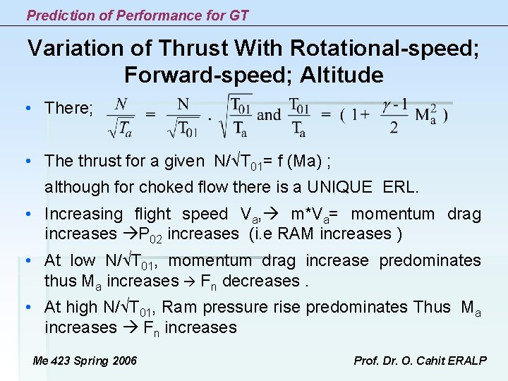
Prediction of Performance for GT Variation of Thrust With Rotational-speed; Forward-speed; Altitude • There; • The thrust for a given N/ T 01= f (Ma) ; although for choked flow there is a UNIQUE ERL. • Increasing flight speed Va, m*Va= momentum drag increases P 02 increases (i. e RAM increases ) • At low N/ T 01, momentum drag increase predominates thus Ma increases Fn decreases. • At high N/ T 01, Ram pressure rise predominates Thus Ma increases Fn increases Me 423 Spring 2006 Prof. Dr. O. Cahit ERALP
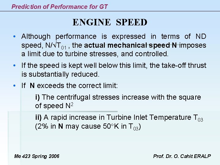
Prediction of Performance for GT ENGINE SPEED • Although performance is expressed in terms of ND speed, N/ T 01 , the actual mechanical speed N imposes a limit due to turbine stresses, and controlled. • If the speed is kept well below this limit, the take-off thrust is substantially reduced. • If N exceeds the correct limit: i) The centrifugal stresses increase with the square of speed N 2 ii) A rapid increase in Turbine Inlet Temperature T 03 (2% in N may cause 50 K in T 03) Me 423 Spring 2006 Prof. Dr. O. Cahit ERALP
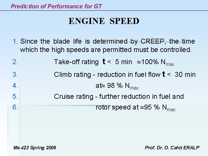
Prediction of Performance for GT ENGINE SPEED 1. Since the blade life is determined by CREEP, the time which the high speeds are permitted must be controlled. 2. Take-off rating t < 5 min 100% Nmax 3. Climb rating - reduction in fuel flow t < 30 min 4. 5. at 98 % Nmax Cruise rating - further reduction in fuel and 6. Me 423 Spring 2006 rotor speed at 95 % Nmax Prof. Dr. O. Cahit ERALP
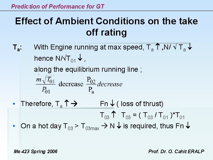
Prediction of Performance for GT Effect of Ambient Conditions on the take off rating T a: With Engine running at max speed, Ta , N/ Ta hence N/ T 01 , along the equilibrium running line ; • Therefore, Ta Fn ( loss of thrust) T 03 = ( T 03 / T 01 )*T 01 • On a hot day T 03 > T 03 max N is required, thus Fn Me 423 Spring 2006 Prof. Dr. O. Cahit ERALP
Prediction of Performance for GT Effect of Ambient Conditions on the take off rating P a: Fn and Pa in direct proportion (since (F / Pa). . . ) Altitude , Pa and Ta ( up to 11000 m) since as Pa Fn but as Ta Fn Then Fn • Therefore ; thrust decreases with increase in altitude. • Airports at high altitudes, especially around tropical zones are critical (Mexico-City, Nairobi ) suffer from this problem. Me 423 Spring 2006 Prof. Dr. O. Cahit ERALP
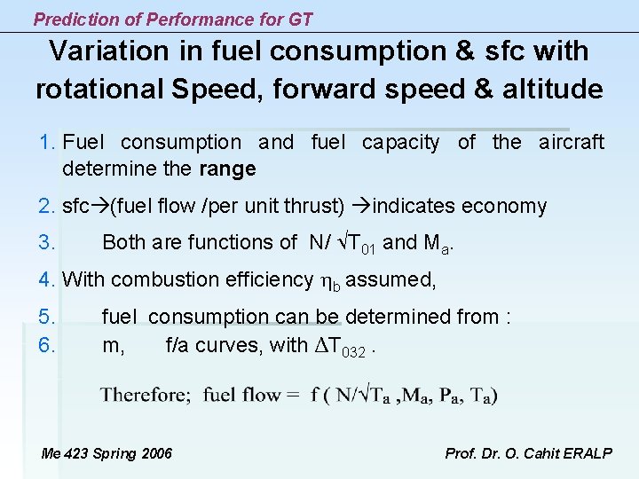
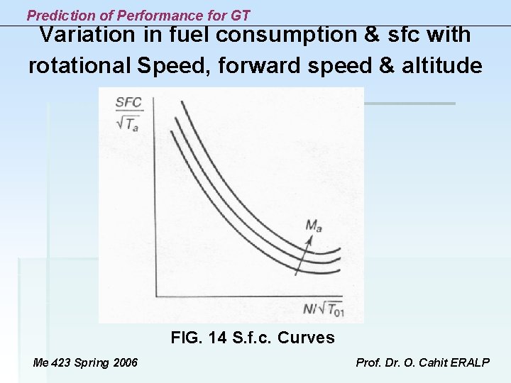
Prediction of Performance for GT Variation in fuel consumption & sfc with rotational Speed, forward speed & altitude 1. Fuel consumption and fuel capacity of the aircraft determine the range 2. sfc (fuel flow /per unit thrust) indicates economy 3. Both are functions of N/ T 01 and Ma. 4. With combustion efficiency b assumed, 5. 6. fuel consumption can be determined from : m, f/a curves, with ΔT 032. Me 423 Spring 2006 Prof. Dr. O. Cahit ERALP
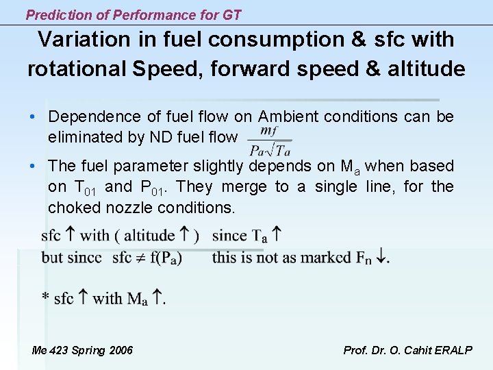
Prediction of Performance for GT Variation in fuel consumption & sfc with rotational Speed, forward speed & altitude • Dependence of fuel flow on Ambient conditions can be eliminated by ND fuel flow • The fuel parameter slightly depends on Ma when based on T 01 and P 01. They merge to a single line, for the choked nozzle conditions. Me 423 Spring 2006 Prof. Dr. O. Cahit ERALP
Prediction of Performance for GT Variation in fuel consumption & sfc with rotational Speed, forward speed & altitude FIG. 14 S. f. c. Curves Me 423 Spring 2006 Prof. Dr. O. Cahit ERALP
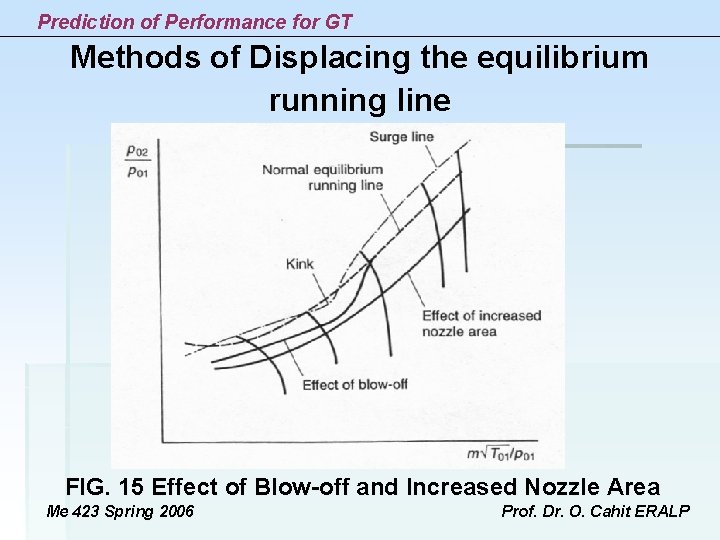
Prediction of Performance for GT Methods of Displacing the Equilibrium Running Line 1. If the Equilibrium Running Line (ERL) intersects the Surge Line (SL), it is not possible to bring the engine up to full power directly. 2. The compressor may surge when the engine accelerates even ERL is not cutting the SL. 3. Many high performance compressors have a kink in the SL. 4. A running line intersecting SL at low N/ T 01 and at the kink is shown in Figure 15. 5. To overcome ERL is lowered down in dangerous regions. Me 423 Spring 2006 Prof. Dr. O. Cahit ERALP
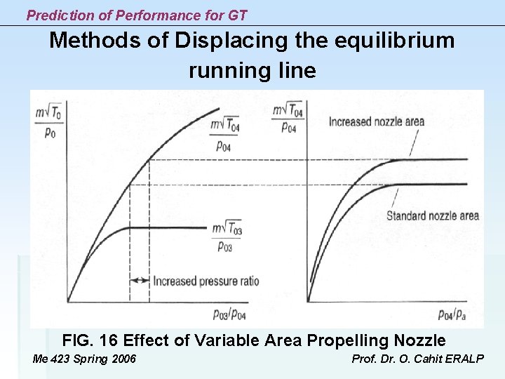
Prediction of Performance for GT Methods of Displacing the equilibrium running line 1. BLOW-OFF is a method to achieve this. 2. Air is bled from some intermediate compressor stage. 3. Some turbine work is wasted. 4. blow-off valve only operates when it is essential. 5. Variable Area Propelling Nozzle; an alternative method to blow-off. 6. Either method will produce a reduction in P 02/P 01 at a given N/ T 01, hence lower the ERL. Me 423 Spring 2006 Prof. Dr. O. Cahit ERALP
Prediction of Performance for GT Methods of Displacing the equilibrium running line FIG. 15 Effect of Blow-off and Increased Nozzle Area Me 423 Spring 2006 Prof. Dr. O. Cahit ERALP
Prediction of Performance for GT Methods of Displacing the equilibrium running line FIG. 16 Effect of Variable Area Propelling Nozzle Me 423 Spring 2006 Prof. Dr. O. Cahit ERALP
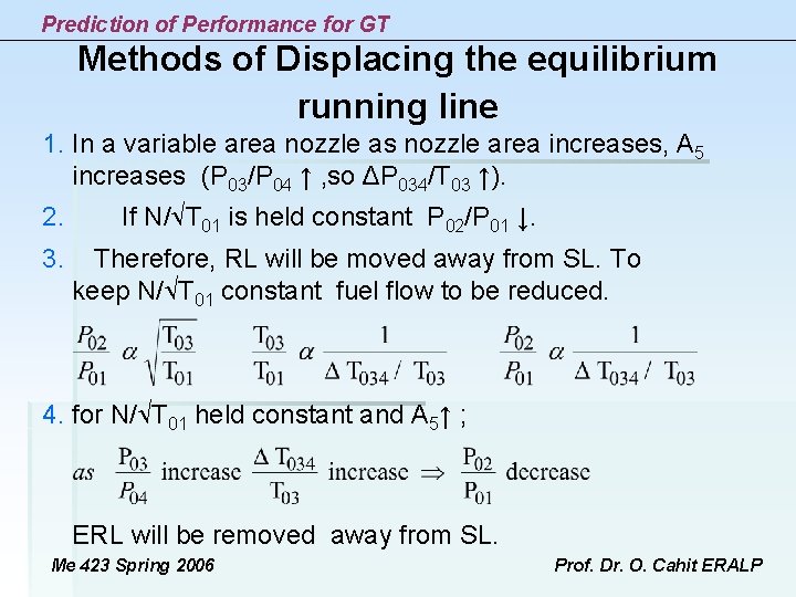
Prediction of Performance for GT Methods of Displacing the equilibrium running line 1. In a variable area nozzle as nozzle area increases, A 5 increases (P 03/P 04 ↑ , so ΔP 034/T 03 ↑). 2. If N/ T 01 is held constant P 02/P 01 ↓. 3. Therefore, RL will be moved away from SL. To keep N/ T 01 constant fuel flow to be reduced. 4. for N/ T 01 held constant and A 5↑ ; ERL will be removed away from SL. Me 423 Spring 2006 Prof. Dr. O. Cahit ERALP