
Attrition Prediction Model for Chemical Looping and Other

- Slides: 15
Attrition Prediction Model for Chemical Looping and Other CFB Systems Nathan Galinsky, Samuel Bayham, and Ronald Breault August 8 th, 2017
Outline • Motivation-Chemical Looping Combustion • Attrition Mechanisms • Attrition Model Features • Example Chemical Looping Case • Future of Development • Conclusions 2
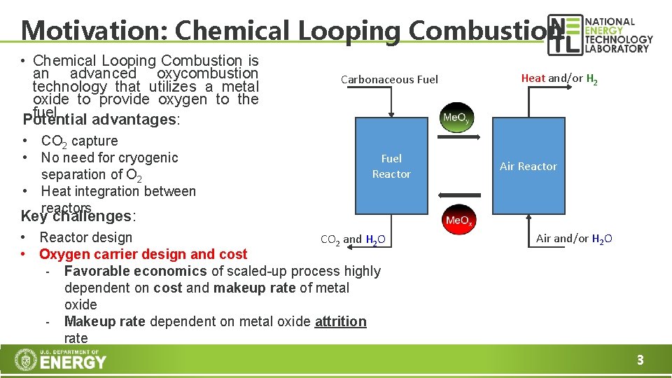
Motivation: Chemical Looping Combustion • Chemical Looping Combustion is an advanced oxycombustion technology that utilizes a metal oxide to provide oxygen to the fuel. Potential advantages: • CO 2 capture • No need for cryogenic separation of O 2 • Heat integration between reactors Carbonaceous Fuel Reactor Heat and/or H 2 Air Reactor Key challenges: • Reactor design CO 2 and H 2 O • Oxygen carrier design and cost - Favorable economics of scaled-up process highly dependent on cost and makeup rate of metal oxide - Makeup rate dependent on metal oxide attrition rate Air and/or H 2 O 3
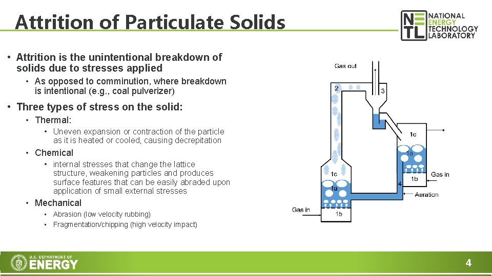
Attrition of Particulate Solids • Attrition is the unintentional breakdown of solids due to stresses applied • As opposed to comminution, where breakdown is intentional (e. g. , coal pulverizer) • Three types of stress on the solid: • Thermal: • Uneven expansion or contraction of the particle as it is heated or cooled, causing decrepitation • Chemical • internal stresses that change the lattice structure, weakening particles and produces surface features that can be easily abraded upon application of small external stresses • Mechanical • Abrasion (low velocity rubbing) • Fragmentation/chipping (high velocity impact) 4
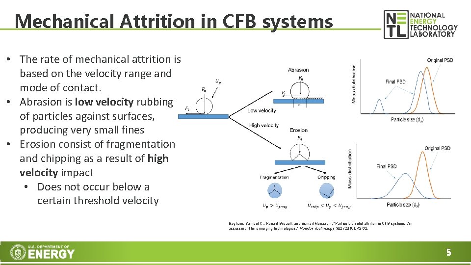
Mechanical Attrition in CFB systems • The rate of mechanical attrition is based on the velocity range and mode of contact. • Abrasion is low velocity rubbing of particles against surfaces, producing very small fines • Erosion consist of fragmentation and chipping as a result of high velocity impact • Does not occur below a certain threshold velocity Bayham, Samuel C. , Ronald Breault, and Esmail Monazam. "Particulate solid attrition in CFB systems–An assessment for emerging technologies. " Powder Technology 302 (2016): 42 -62. 5
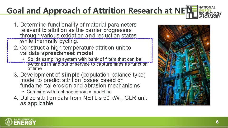
Goal and Approach of Attrition Research at NETL 1. Determine functionality of material parameters relevant to attrition as the carrier progresses through various oxidation and reduction states while thermally cycling. 2. Construct a high temperature attrition unit to validate spreadsheet model • Solids sampling system with bank of filters that can be switched in and out of service to capture fines as function of time 3. Development of simple (population-balance type) model to predict attrition losses based on fundamental erosion and abrasion mechanisms • Combine with technoeconomic modeling 4. Utilize attrition data from NETL’s 50 k. Wth CLR unit as applicable 6
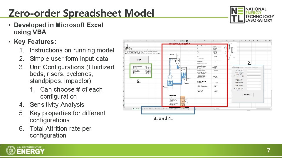
Zero-order Spreadsheet Model • Developed in Microsoft Excel using VBA • Key Features: 1. Instructions on running model 2. Simple user form input data 3. Unit Configurations (Fluidized beds, risers, cyclones, standpipes, impactor) 1. Can choose # of each configuration 4. Sensitivity Analysis 5. Key properties for different configurations 6. Total Attrition rate per configuration 5. 1. 2. 6. 3. and 4. 7
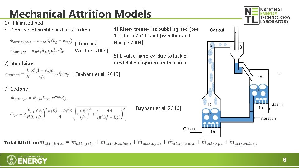
Mechanical Attrition Models 1) Fluidized bed • Consists of bubble and jet attrition 2) Standpipe [Thon and Werther 2009] 4) Riser- treated as bubbling bed (see 1. ) [Thon 2011] and [Werther and Hartge 2004] 5) L-valve- ignored due to lack of model development in this area [Bayham et al. 2016] 3) Cyclone [Bayham et al. 2016] Total Attrition: 8
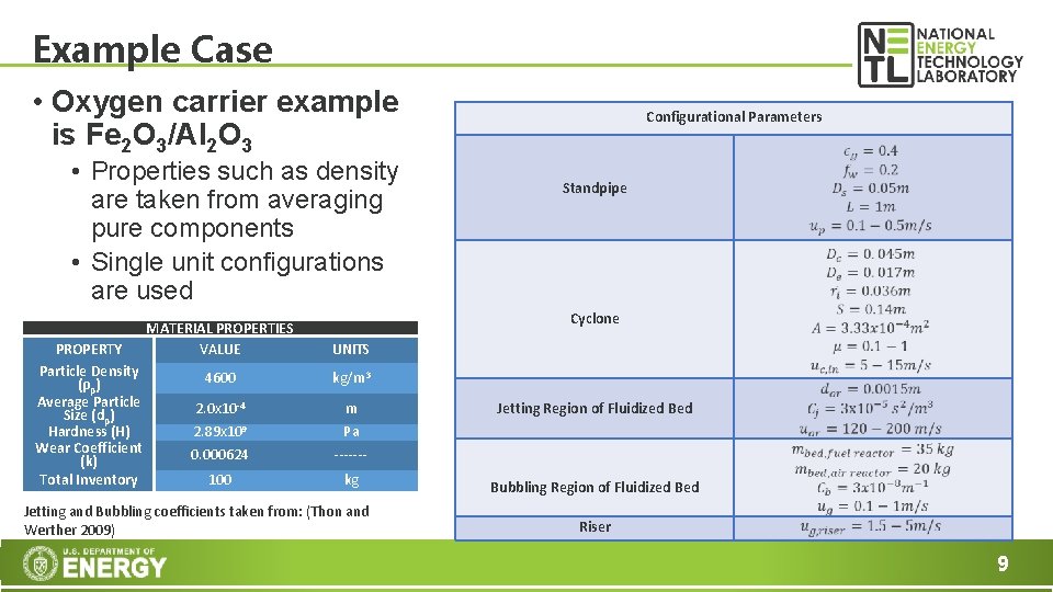
Example Case • Oxygen carrier example is Fe 2 O 3/Al 2 O 3 • Properties such as density are taken from averaging pure components • Single unit configurations are used PROPERTY Particle Density (ρp) Average Particle Size (dp) Hardness (H) Wear Coefficient (k) Total Inventory MATERIAL PROPERTIES VALUE UNITS 4600 kg/m 3 2. 0 x 10 -4 m 2. 89 x 109 Pa 0. 000624 ------- 100 kg Jetting and Bubbling coefficients taken from: (Thon and Werther 2009) Configurational Parameters Standpipe Cyclone Jetting Region of Fluidized Bubbling Region of Fluidized Bed Riser 9
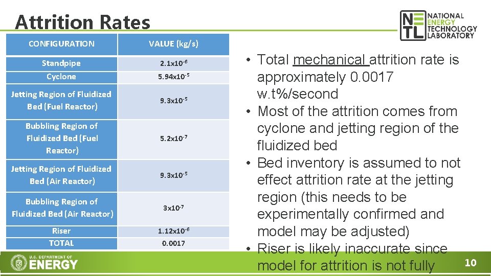
Attrition Rates CONFIGURATION VALUE (kg/s) Standpipe Cyclone 2. 1 x 10 -6 5. 94 x 10 -5 Jetting Region of Fluidized Bed (Fuel Reactor) 9. 3 x 10 -5 Bubbling Region of Fluidized Bed (Fuel Reactor) 5. 2 x 10 -7 Jetting Region of Fluidized Bed (Air Reactor) 9. 3 x 10 -5 Bubbling Region of Fluidized Bed (Air Reactor) 3 x 10 -7 Riser TOTAL 1. 12 x 10 -6 0. 0017 • Total mechanical attrition rate is approximately 0. 0017 w. t%/second • Most of the attrition comes from cyclone and jetting region of the fluidized bed • Bed inventory is assumed to not effect attrition rate at the jetting region (this needs to be experimentally confirmed and model may be adjusted) • Riser is likely inaccurate since 10 model for attrition is not fully
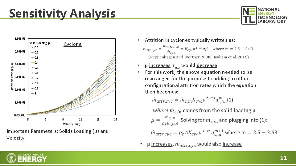
Sensitivity Analysis Cyclone • Attrition in cyclones typically written as: • μ increases, rattr would decrease • For this work, the above equation needed to be rearranged for the purpose to adding to other configurational attrition rates which the equation then becomes: Important Parameters: Solids Loading (μ) and Velocity 11
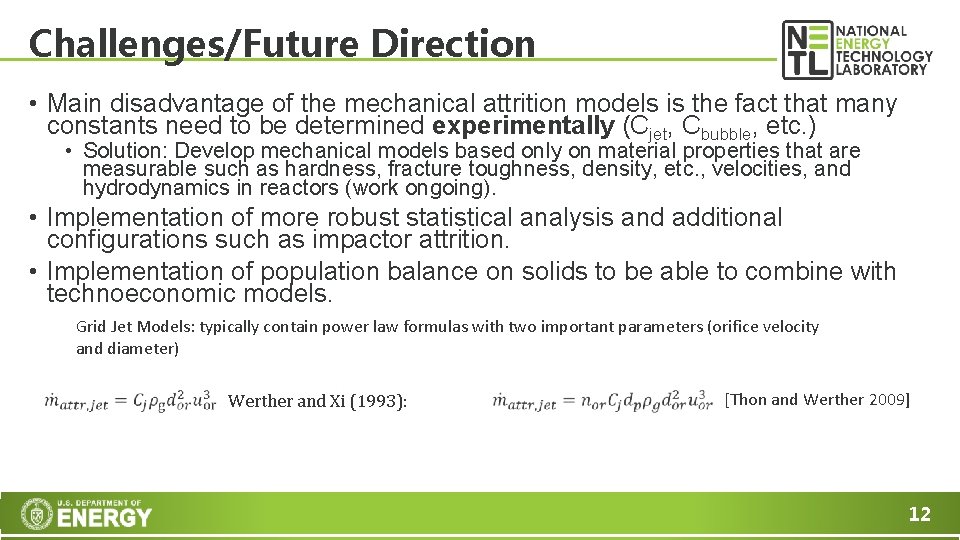
Challenges/Future Direction • Main disadvantage of the mechanical attrition models is the fact that many constants need to be determined experimentally (Cjet, Cbubble, etc. ) • Solution: Develop mechanical models based only on material properties that are measurable such as hardness, fracture toughness, density, etc. , velocities, and hydrodynamics in reactors (work ongoing). • Implementation of more robust statistical analysis and additional configurations such as impactor attrition. • Implementation of population balance on solids to be able to combine with technoeconomic models. Grid Jet Models: typically contain power law formulas with two important parameters (orifice velocity and diameter) Werther and Xi (1993): [Thon and Werther 2009] 12
Concluding Remarks • A simple zero-order spreadsheet model for attrition is developed in Excel and VBA • An example case using hematite/alumina oxygen carrier is investigated using previously developed mechanical models for attrition in different parts of chemical looping CFB units. • Future development of attrition models for various configurations are needed. 13
Acknowledgements • This research was supported in part by an appointment to the National Energy Technology Laboratory Research Participation Program, sponsored by the U. S. Department of Energy and administered by the Oak Ridge Institute for Science and Education. 14
Disclaimer This project was funded by the Department of Energy, National Energy Technology Laboratory, an agency of the United States Government, through a support contract with URS Energy & Construction, Inc. Neither the United States Government nor any agency thereof, nor any of their employees, nor URS Energy & Construction, Inc. , nor any of their employees, makes any warranty, expressed or implied, or assumes any legal liability or responsibility for the accuracy, completeness, or usefulness of any information, apparatus, product, or process disclosed, or represents that its use would not infringe privately owned rights. Reference herein to any specific commercial product, process, or service by trade name, trademark, manufacturer, or otherwise, does not necessarily constitute or imply its endorsement, recommendation, or favoring by the United States Government or any agency thereof. The views and opinions of authors expressed herein do not necessarily state or reflect those of the United States Government or any agency thereof. 15