Master Thesis at SKF Lateral force estimation acting





- Slides: 57
Master Thesis at SKF: Lateral force estimation acting at a vehicle wheel using a hub bearing unit equipped with strain gauges and Eddy-current sensors By: John den Engelse Date: 19 – 6 - 2013 Challenge the future 1
Presentation overview • Introduction • Research goals • Strain gauge measurements • Eddy-current sensor measurements • Field- / validation measurements • BETSY calibration method • Conclusions Challenge the future 2
1 Introduction Challenge the future 3
Introduction: Load Sensing Bearing (LSB) • Why would we like to measure forces? • Monitoring the mechanical loads of a bearing. • Control the active safety systems in vehicles like the ABS (longitudinal force) and ESC (lateral force). • Measure the vertical load in, for instance, trucks. Challenge the future 4 Introduction – Research goals – Strain gauge measurements – Eddy-current sensors measurements – Field- / validation measurements - …
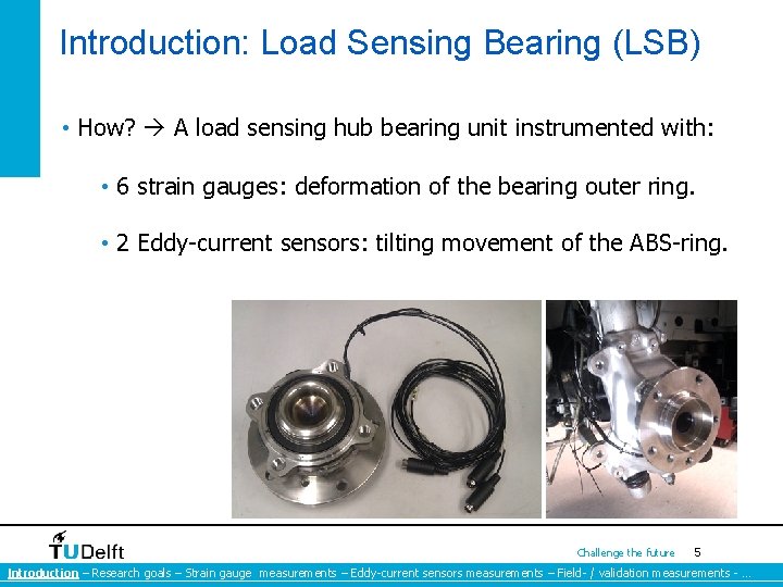
Introduction: Load Sensing Bearing (LSB) • How? A load sensing hub bearing unit instrumented with: • 6 strain gauges: deformation of the bearing outer ring. • 2 Eddy-current sensors: tilting movement of the ABS-ring. Challenge the future 5 Introduction – Research goals – Strain gauge measurements – Eddy-current sensors measurements – Field- / validation measurements - …
2 Research goals Challenge the future 6
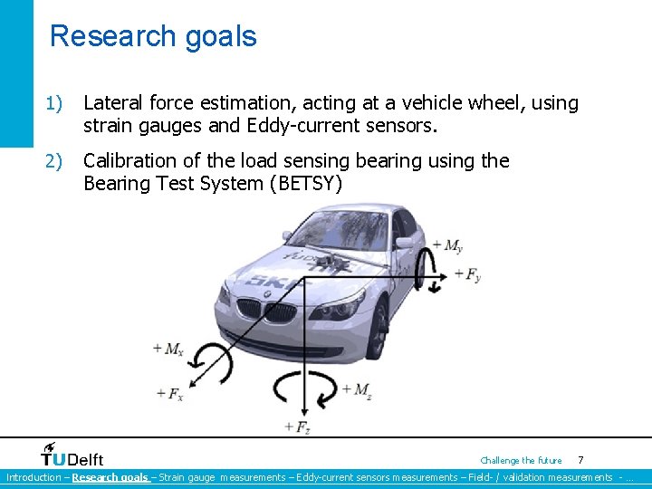
Research goals 1) Lateral force estimation, acting at a vehicle wheel, using strain gauges and Eddy-current sensors. 2) Calibration of the load sensing bearing using the Bearing Test System (BETSY) Challenge the future 7 Introduction – Research goals – Strain gauge measurements – Eddy-current sensors measurements – Field- / validation measurements - …
3 Strain gauge measurements Challenge the future 8
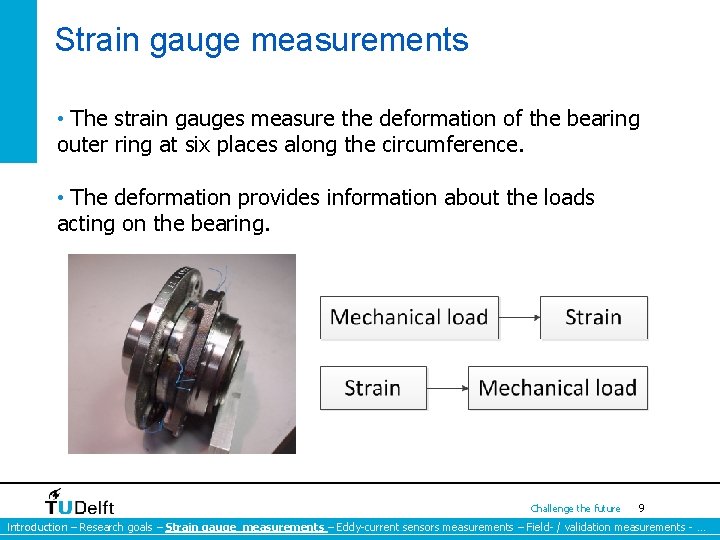
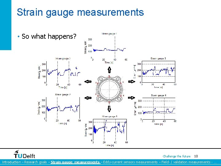
Strain gauge measurements • The strain gauges measure the deformation of the bearing outer ring at six places along the circumference. • The deformation provides information about the loads acting on the bearing. Challenge the future 9 Introduction – Research goals – Strain gauge measurements – Eddy-current sensors measurements – Field- / validation measurements - …
Strain gauge measurements • So what happens? Challenge the future 10 Introduction – Research goals – Strain gauge measurements – Eddy-current sensors measurements – Field- / validation measurements - …
Warning The following slide features a mathematical trick performed by a professional and under the supervision of a professional. Accordingly, the TU Delft and the students must insist that no one attempt to recreate of re-enact any trick or activity performed on this slide.
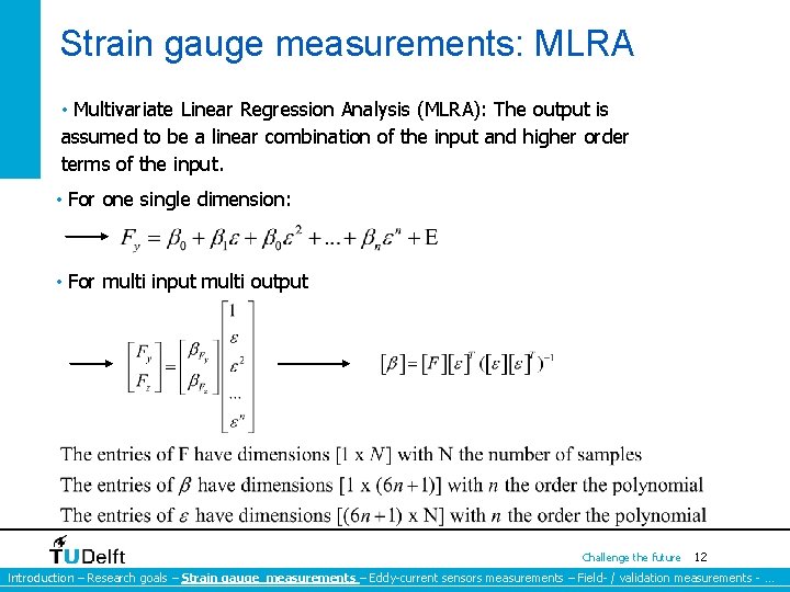
Strain gauge measurements: MLRA • Multivariate Linear Regression Analysis (MLRA): The output is assumed to be a linear combination of the input and higher order terms of the input. • For one single dimension: • For multi input multi output Challenge the future 12 Introduction – Research goals – Strain gauge measurements – Eddy-current sensors measurements – Field- / validation measurements - …
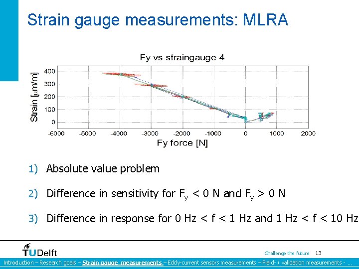
Strain gauge measurements: MLRA 1) Absolute value problem 2) Difference in sensitivity for Fy < 0 N and Fy > 0 N 3) Difference in response for 0 Hz < f < 1 Hz and 1 Hz < f < 10 Hz Challenge the future 13 Introduction – Research goals – Strain gauge measurements – Eddy-current sensors measurements – Field- / validation measurements - …
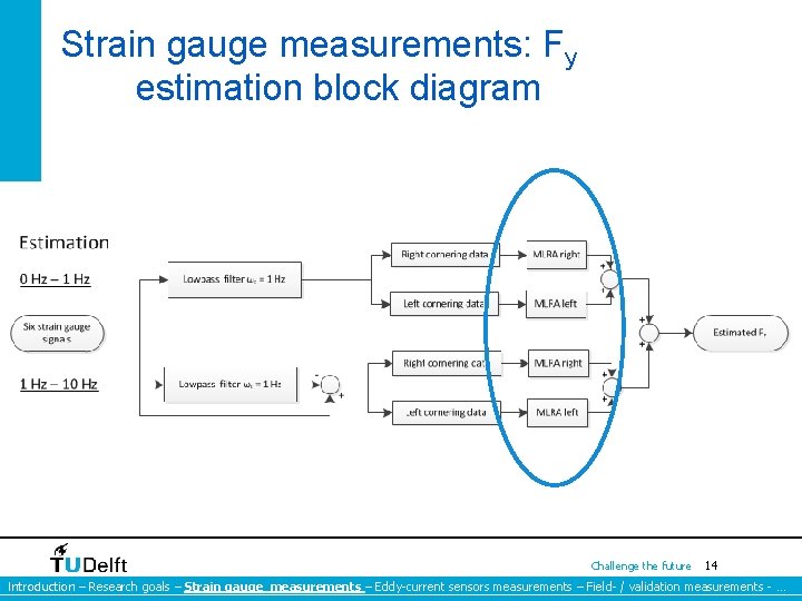
Strain gauge measurements: Fy estimation block diagram Challenge the future 14 Introduction – Research goals – Strain gauge measurements – Eddy-current sensors measurements – Field- / validation measurements - …
4 Eddy-current sensor measurements Challenge the future 15
Eddy-current sensor measurement • Why (inductive) Eddy-current sensor measurements? • The strain gauges are subject to the absolute value problem. • Strain measurements are subject to low frequent thermal influences. Challenge the future 16 Introduction – Research goals – Strain gauge measurements – Eddy-current sensors measurements – Field- / validation measurements - …
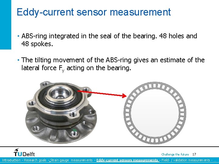
Eddy-current sensor measurement • ABS-ring integrated in the seal of the bearing. 48 holes and 48 spokes. • The tilting movement of the ABS-ring gives an estimate of the lateral force Fy acting on the bearing. Challenge the future 17 Introduction – Research goals – Strain gauge measurements – Eddy-current sensors measurements – Field- / validation measurements - …
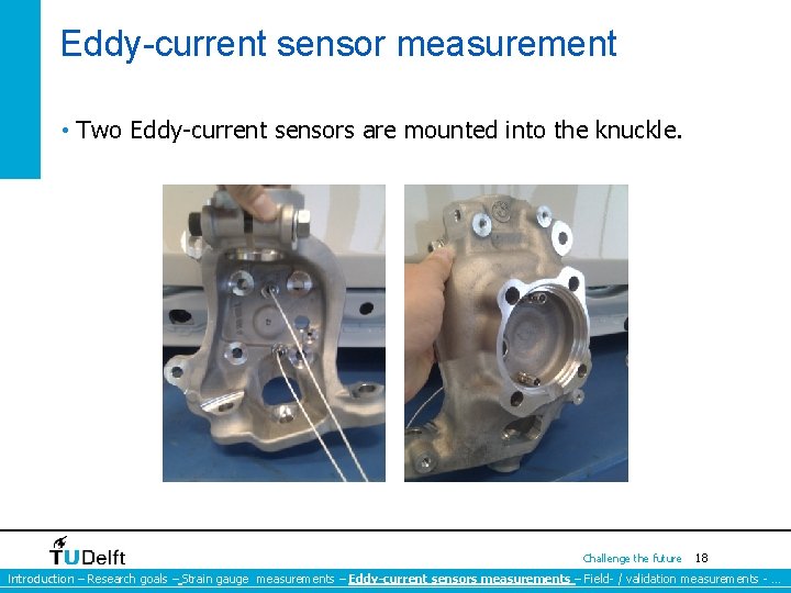
Eddy-current sensor measurement • Two Eddy-current sensors are mounted into the knuckle. Challenge the future 18 Introduction – Research goals – Strain gauge measurements – Eddy-current sensors measurements – Field- / validation measurements - …
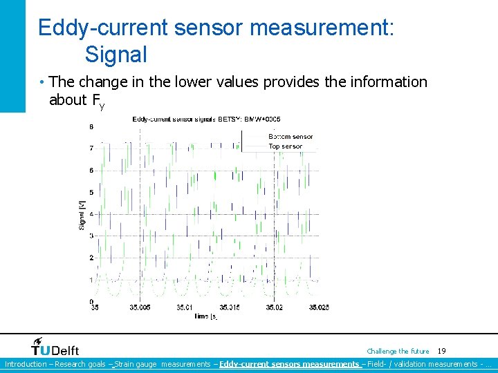
Eddy-current sensor measurement: Signal • The change in the lower values provides the information about Fy Challenge the future 19 Introduction – Research goals – Strain gauge measurements – Eddy-current sensors measurements – Field- / validation measurements - …
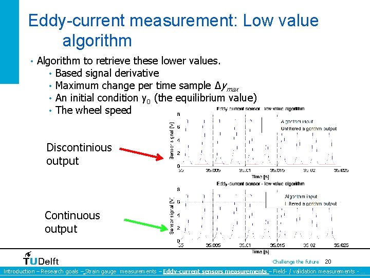
Eddy-current measurement: Low value algorithm • Algorithm to retrieve these lower values. • Based signal derivative • Maximum change per time sample ∆ymax • An initial condition y 0 (the equilibrium value) • The wheel speed Discontinious output Continuous output Challenge the future 20 Introduction – Research goals – Strain gauge measurements – Eddy-current sensors measurements – Field- / validation measurements - …
5 Field measurements Challenge the future 21
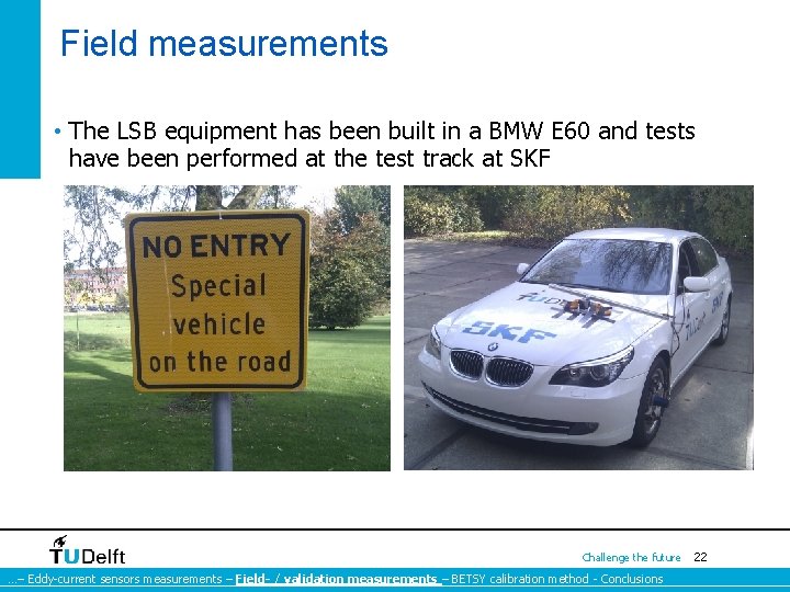
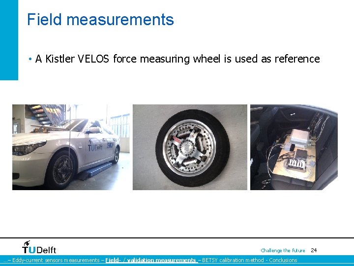
Field measurements • The LSB equipment has been built in a BMW E 60 and tests have been performed at the test track at SKF Challenge the future …– Eddy-current sensors measurements – Field- / validation measurements – BETSY calibration method - Conclusions 22
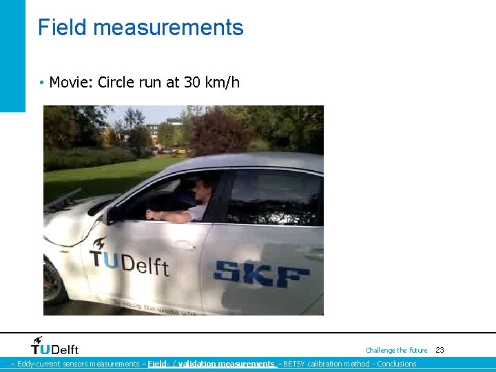
Field measurements • Movie: Circle run at 30 km/h Challenge the future …– Eddy-current sensors measurements – Field- / validation measurements – BETSY calibration method - Conclusions 23
Field measurements • A Kistler VELOS force measuring wheel is used as reference Challenge the future …– Eddy-current sensors measurements – Field- / validation measurements – BETSY calibration method - Conclusions 24
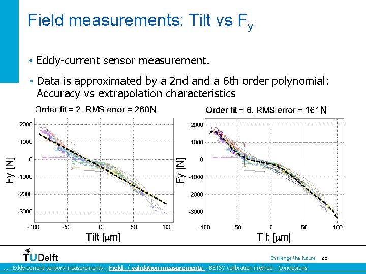
Field measurements: Tilt vs Fy • Eddy-current sensor measurement. • Data is approximated by a 2 nd a 6 th order polynomial: Accuracy vs extrapolation characteristics N N Challenge the future …– Eddy-current sensors measurements – Field- / validation measurements – BETSY calibration method - Conclusions 25
Field measurements • Strain measurement Challenge the future …– Eddy-current sensors measurements – Field- / validation measurements – BETSY calibration method - Conclusions 26
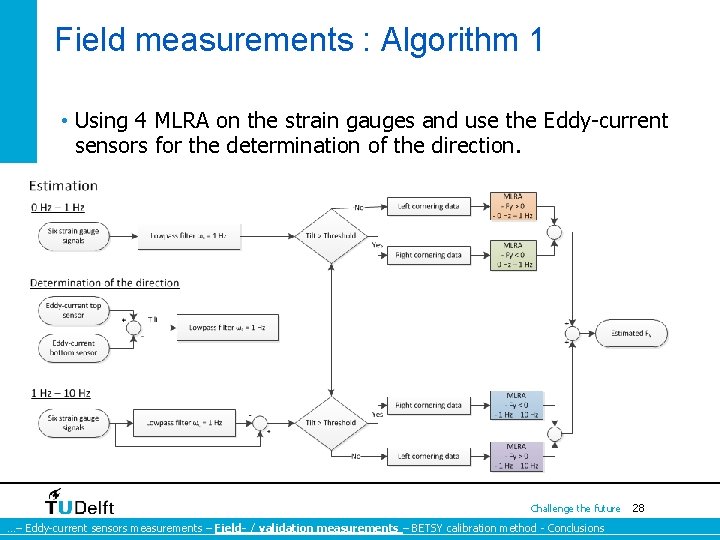
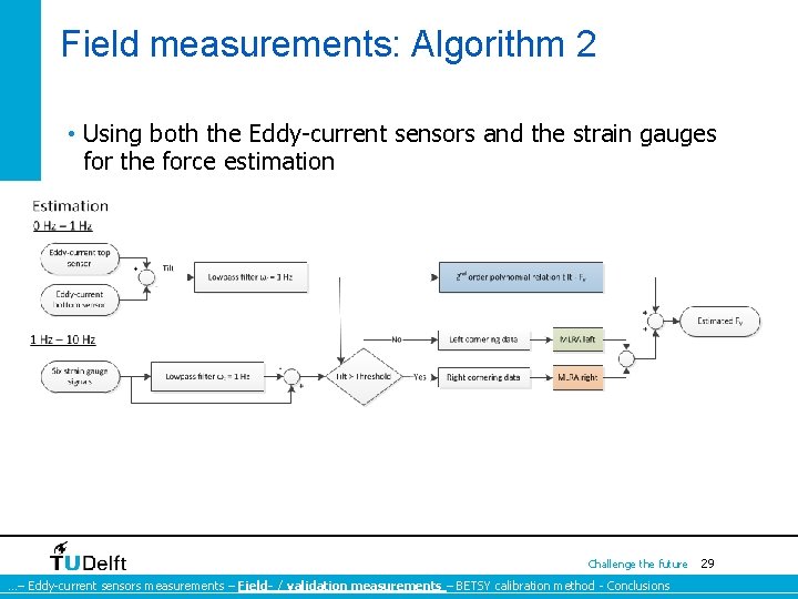
Field measurements : Fy estimation • Two force estimation algorithms. Both for an in-situ calibration and a BETSY calibration. 1) Using 4 MLRA on the strain gauges and use the Eddy- current sensors for the determination of the direction. 2) Using both the Eddy-current sensors and the strain gauges for the force estimation. Challenge the future …– Eddy-current sensors measurements – Field- / validation measurements – BETSY calibration method - Conclusions 27
Field measurements : Algorithm 1 • Using 4 MLRA on the strain gauges and use the Eddy-current sensors for the determination of the direction. Challenge the future …– Eddy-current sensors measurements – Field- / validation measurements – BETSY calibration method - Conclusions 28
Field measurements: Algorithm 2 • Using both the Eddy-current sensors and the strain gauges for the force estimation Challenge the future …– Eddy-current sensors measurements – Field- / validation measurements – BETSY calibration method - Conclusions 29
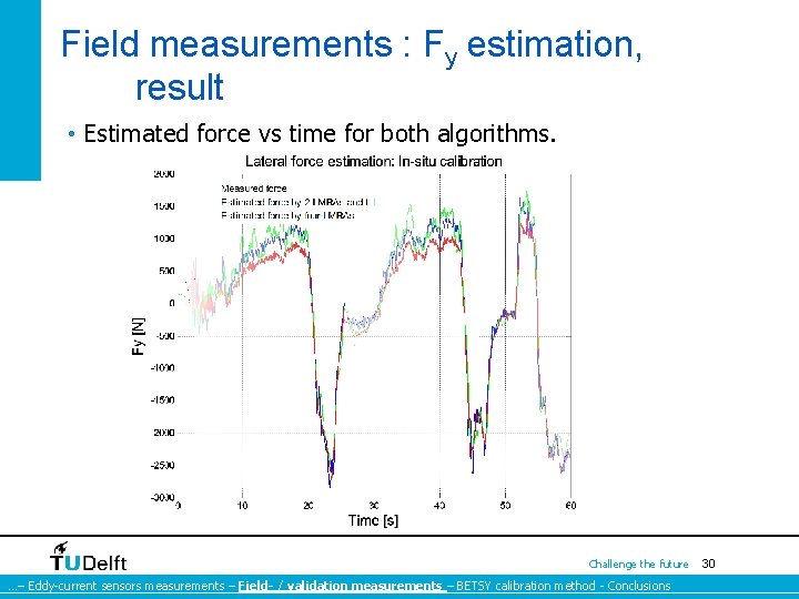
Field measurements : Fy estimation, result • Estimated force vs time for both algorithms. Challenge the future …– Eddy-current sensors measurements – Field- / validation measurements – BETSY calibration method - Conclusions 30
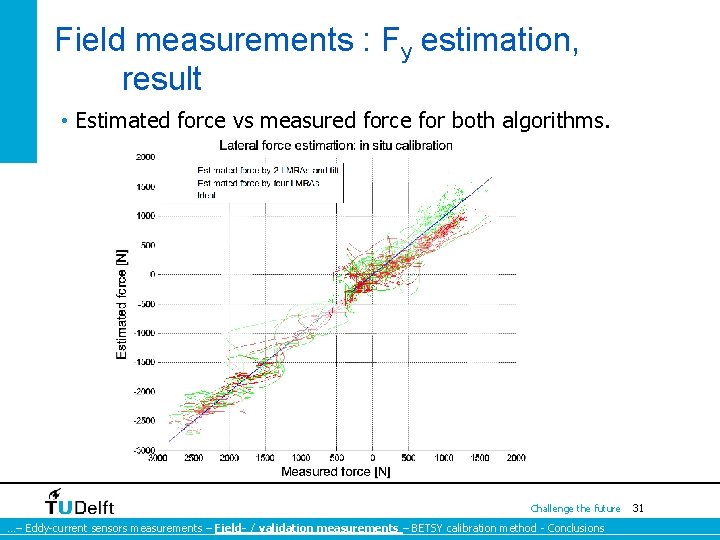
Field measurements : Fy estimation, result • Estimated force vs measured force for both algorithms. Challenge the future …– Eddy-current sensors measurements – Field- / validation measurements – BETSY calibration method - Conclusions 31
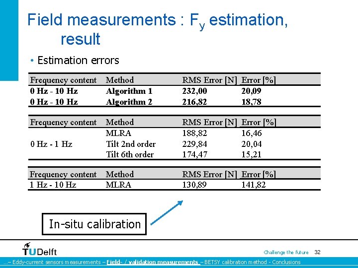
Field measurements : Fy estimation, result • Estimation errors Frequency content 0 Hz - 10 Hz Method Algorithm 1 Algorithm 2 RMS Error [N] Error [%] 232, 00 20, 09 216, 82 18, 78 Frequency content 0 Hz - 1 Hz Method MLRA Tilt 2 nd order Tilt 6 th order RMS Error [N] 188, 82 229, 84 174, 47 Frequency content 1 Hz - 10 Hz Method MLRA RMS Error [N] Error [%] 130, 89 141, 82 Error [%] 16, 46 20, 04 15, 21 In-situ calibration Challenge the future …– Eddy-current sensors measurements – Field- / validation measurements – BETSY calibration method - Conclusions 32
6 BETSY calibration Challenge the future 33
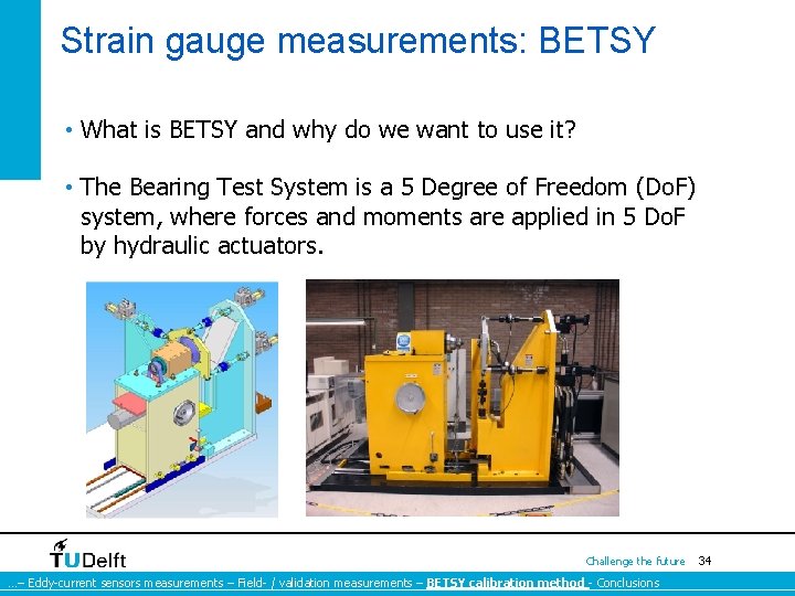
Strain gauge measurements: BETSY • What is BETSY and why do we want to use it? • The Bearing Test System is a 5 Degree of Freedom (Do. F) system, where forces and moments are applied in 5 Do. F by hydraulic actuators. Challenge the future …– Eddy-current sensors measurements – Field- / validation measurements – BETSY calibration method - Conclusions 34
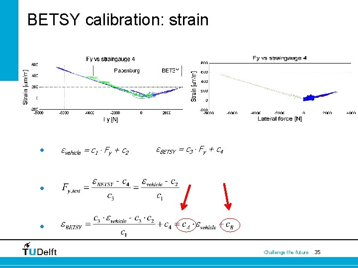
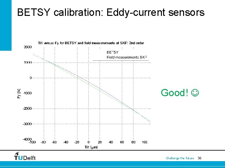
BETSY calibration: strain • εvehicle = c 1 ∙ Fy + c 2 εBETSY = c 3 ∙ Fy + c 4 • • Challenge the future 35
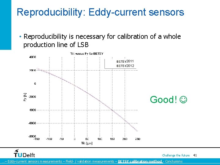
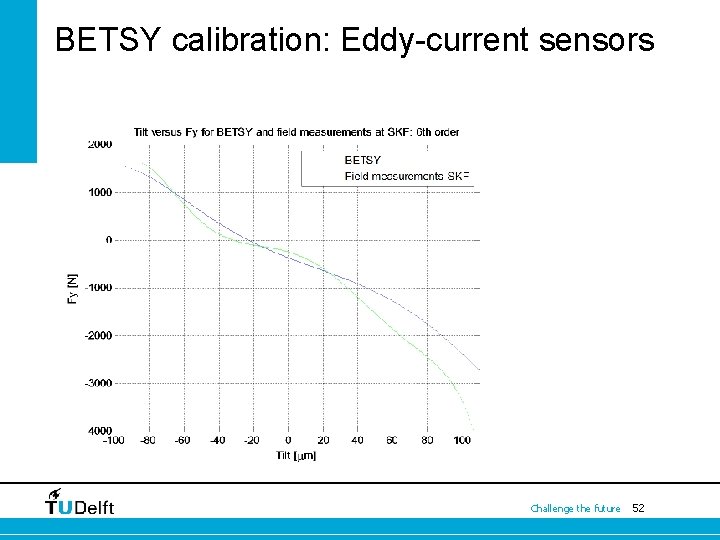
BETSY calibration: Eddy-current sensors Good! Challenge the future 36
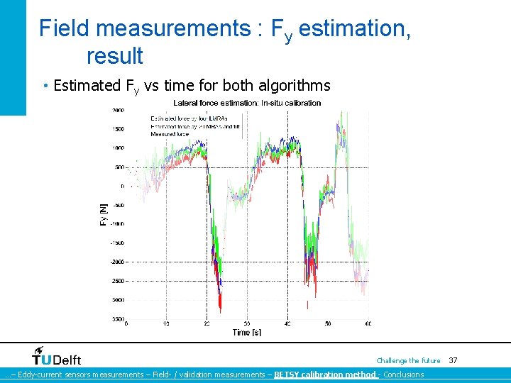
Field measurements : Fy estimation, result • Estimated Fy vs time for both algorithms Challenge the future …– Eddy-current sensors measurements – Field- / validation measurements – BETSY calibration method - Conclusions 37
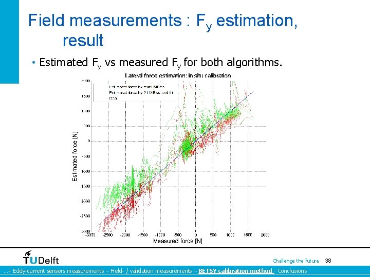
Field measurements : Fy estimation, result • Estimated Fy vs measured Fy for both algorithms. Challenge the future …– Eddy-current sensors measurements – Field- / validation measurements – BETSY calibration method - Conclusions 38
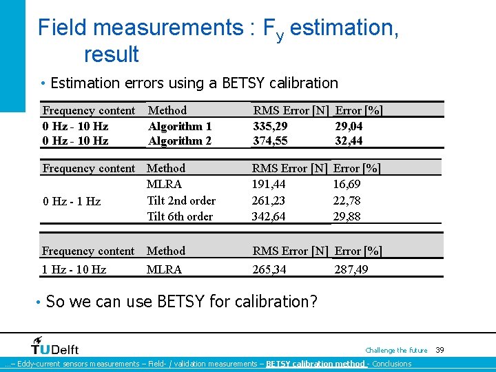
Field measurements : Fy estimation, result • Estimation errors using a BETSY calibration Frequency content 0 Hz - 10 Hz Method Algorithm 1 Algorithm 2 RMS Error [N] Error [%] 335, 29 29, 04 374, 55 32, 44 Frequency content Method MLRA Tilt 2 nd order 0 Hz - 1 Hz Tilt 6 th order RMS Error [N] 191, 44 261, 23 342, 64 Frequency content 1 Hz - 10 Hz RMS Error [N] Error [%] 265, 34 287, 49 Method MLRA Error [%] 16, 69 22, 78 29, 88 • So we can use BETSY for calibration? Challenge the future …– Eddy-current sensors measurements – Field- / validation measurements – BETSY calibration method - Conclusions 39
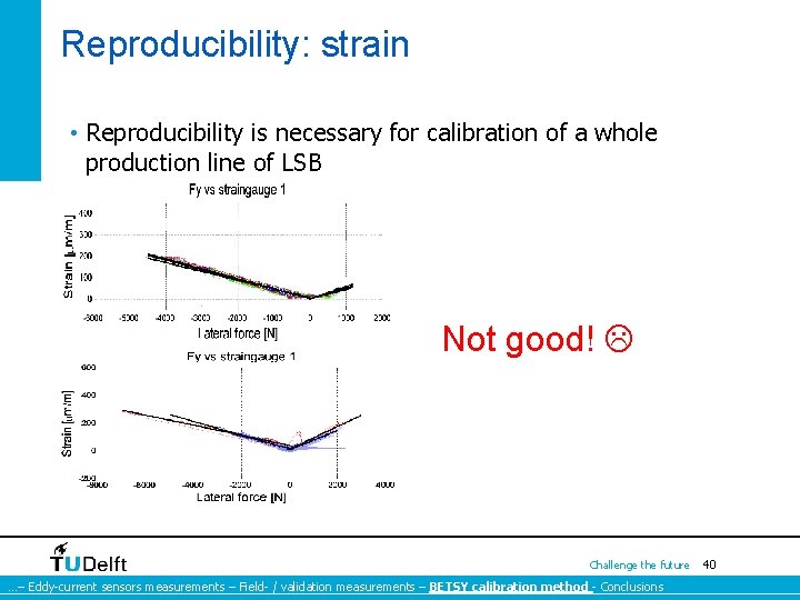
Reproducibility: strain • Reproducibility is necessary for calibration of a whole production line of LSB Not good! Challenge the future …– Eddy-current sensors measurements – Field- / validation measurements – BETSY calibration method - Conclusions 40
Reproducibility: Eddy-current sensors • Reproducibility is necessary for calibration of a whole production line of LSB 2011 2012 Good! Challenge the future …– Eddy-current sensors measurements – Field- / validation measurements – BETSY calibration method - Conclusions 41
7 Conclusions Challenge the future 42
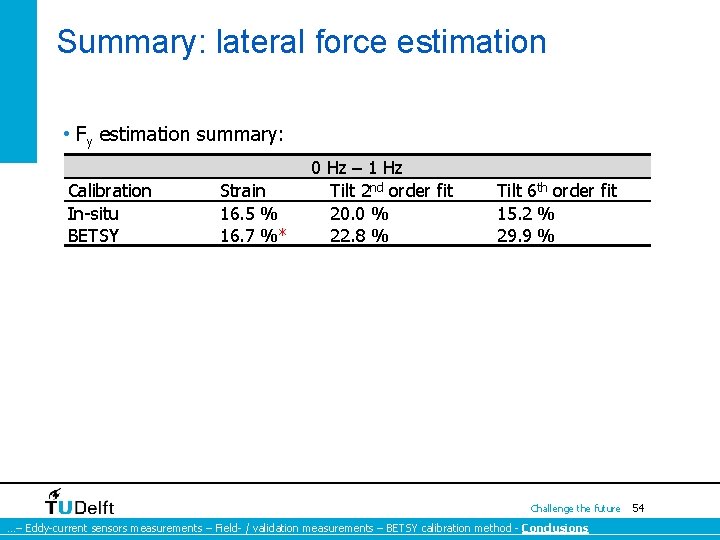
Conclusions: lateral force estimation • In the semi-static frequency range the strain gauges as well as the Eddy-current sensors can be used force estimation with errors ranging from 15 % - 20 %. • In the dynamic frequency range the lateral force is not correlated with the strain and ABS-ring deflection. • Regarding the Eddy-current sensors BETSY can be used for calibration. • Regarding the strain gauges sensors BETSY cannot be used for calibration. Challenge the future …– Eddy-current sensors measurements – Field- / validation measurements – BETSY calibration method - Conclusions 43
Questions? Thank you for your attention ! Challenge the future 44
Backup slides Challenge the future 45
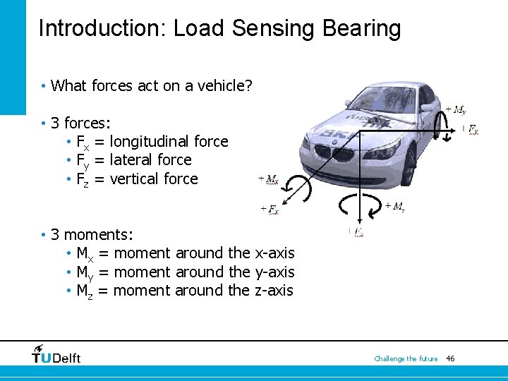
Introduction: Load Sensing Bearing • What forces act on a vehicle? • 3 forces: • Fx = longitudinal force • Fy = lateral force • Fz = vertical force • 3 moments: • Mx = moment around the x-axis • My = moment around the y-axis • Mz = moment around the z-axis Challenge the future 46
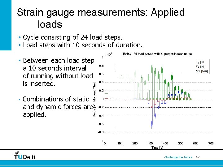
Strain gauge measurements: Applied loads • Cycle consisting of 24 load steps. • Load steps with 10 seconds of duration. • Between each load step a 10 seconds interval of running without load is inserted. • Combinations of static and dynamic forces are applied. Challenge the future 47
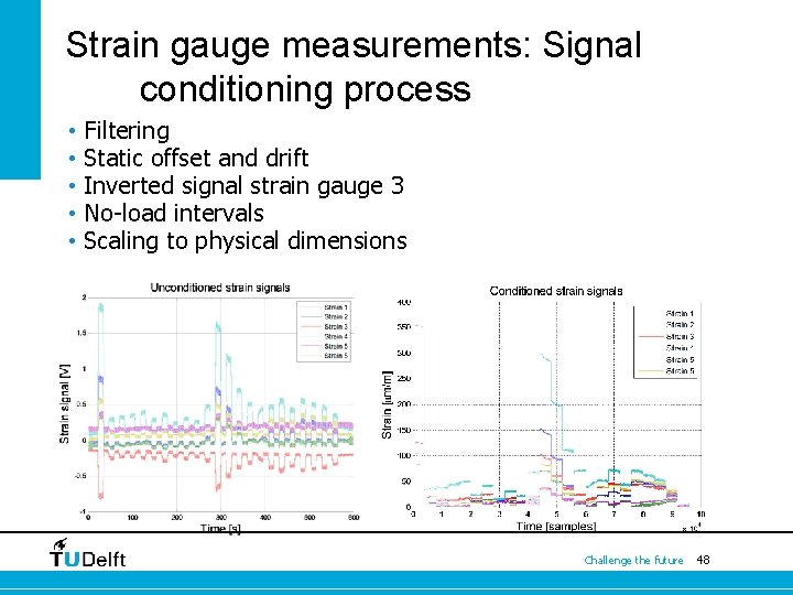
Strain gauge measurements: Signal conditioning process • • • Filtering Static offset and drift Inverted signal strain gauge 3 No-load intervals Scaling to physical dimensions Challenge the future 48
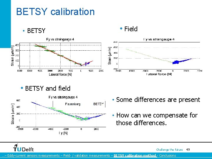
BETSY calibration • BETSY • Field • BETSY and field • Some differences are present • How can we compensate for those differences. Challenge the future …– Eddy-current sensors measurements – Field- / validation measurements – BETSY calibration method - Conclusions 49
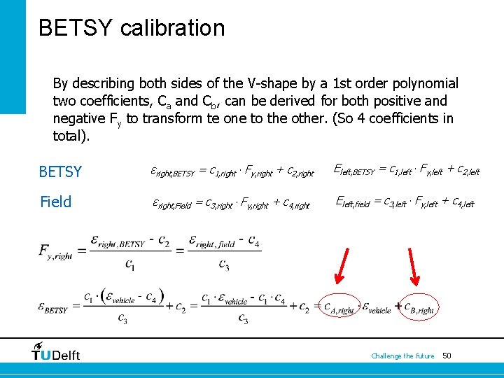
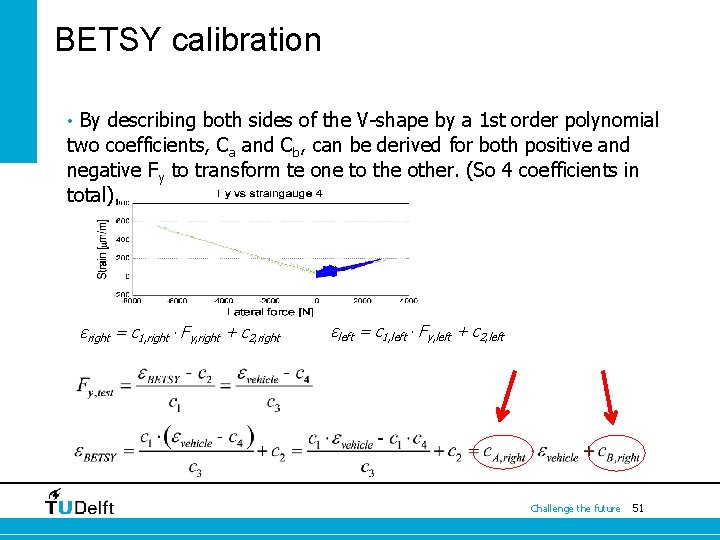
BETSY calibration By describing both sides of the V-shape by a 1 st order polynomial two coefficients, Ca and Cb, can be derived for both positive and negative Fy to transform te one to the other. (So 4 coefficients in total). BETSY εright, BETSY = c 1, right ∙ Fy, right + c 2, right Εleft, BETSY = c 1, left ∙ Fy, left + c 2, left Field εright, Field = c 3, right ∙ Fy, right + c 4, right Εleft, field = c 3, left ∙ Fy, left + c 4, left Challenge the future 50
BETSY calibration • By describing both sides of the V-shape by a 1 st order polynomial two coefficients, Ca and Cb, can be derived for both positive and negative Fy to transform te one to the other. (So 4 coefficients in total). εright = c 1, right ∙ Fy, right + c 2, right εleft = c 1, left ∙ Fy, left + c 2, left Challenge the future 51
BETSY calibration: Eddy-current sensors Challenge the future 52
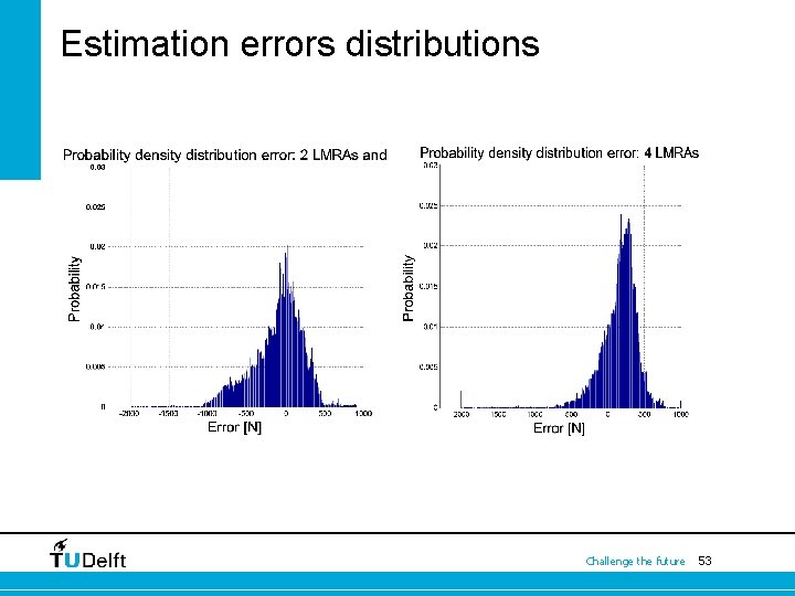
Estimation errors distributions Challenge the future 53
Summary: lateral force estimation • Fy estimation summary: Calibration In-situ BETSY Strain 16. 5 % 16. 7 %* 0 Hz – 1 Hz Tilt 2 nd order fit 20. 0 % 22. 8 % Tilt 6 th order fit 15. 2 % 29. 9 % Challenge the future …– Eddy-current sensors measurements – Field- / validation measurements – BETSY calibration method - Conclusions 54
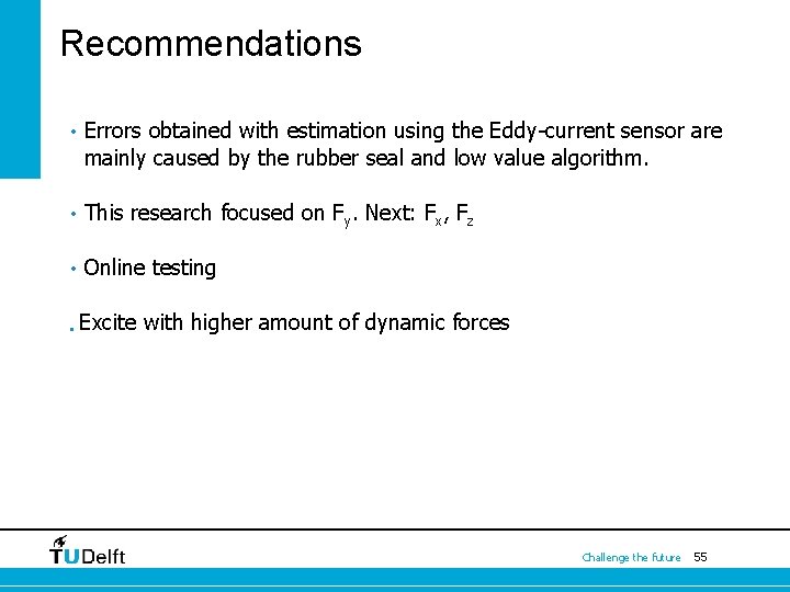
Recommendations • Errors obtained with estimation using the Eddy-current sensor are mainly caused by the rubber seal and low value algorithm. • This research focused on Fy. Next: Fx, Fz • Online testing • Excite with higher amount of dynamic forces Challenge the future 55
Questions? Thank you for your attention ! Challenge the future 56
Questions? Thank you for your attention ! Challenge the future 57