Frame Relay Outline Why do we need Frame


 located within the")

: Are temporary connections used in situations requiring only")
: PVCs are more common. A predefined VC. Used")


 A star topology, also known as a hub and")


- Slides: 44
Frame Relay
Outline Why do we need Frame Relay? Frame Relay Network as a NBMA network Virtual Circuits DLCI Mapping of DLCI Frame Relay Topologies
Why do we need Frame Relay? Frame Relay is more complex a technology than pointto-point WAN links but also provides more features and benefits
Why do we need Frame Relay? Leased lines provide permanent dedicated capacity and are used extensively for building WANs. Disadvantages A fixed capacity (WAN traffic is often variable) Equipment costs
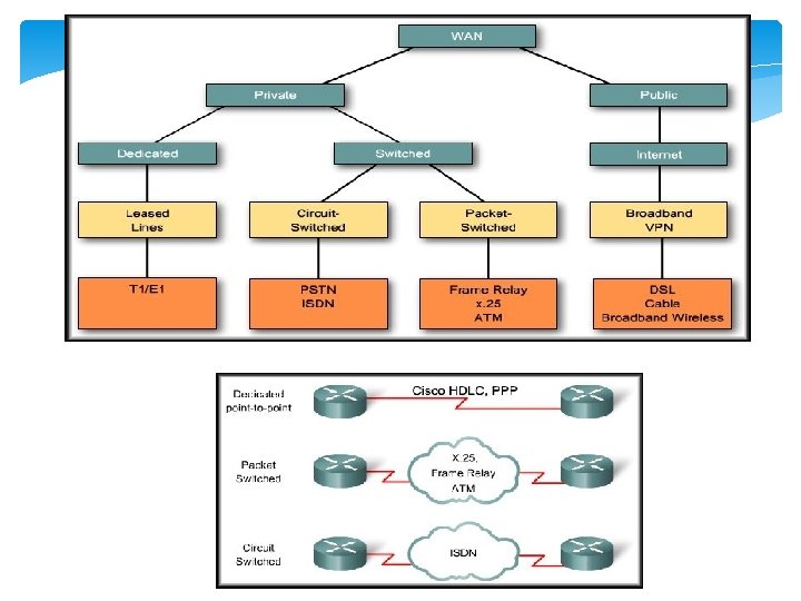
Why do we need Frame Relay? An alternative to dedicated, expensive, leased WAN lines is Frame Relay is a high-performance WAN protocol that operates at the physical and data link layers of the OSI reference model. Frame Relay provides a cost-efficient solution for communications between multiple remote sites by using a single access circuit from each site to the provider.
• The capacity between any two sites can vary.
Frame Relay Network access switches
Frame Relay Network A Frame Relay network is made up of a large number of Frame Relay switches dispersed all over the coverage area of a Frame Relay service provider (e. g. region or country) The switches are interconnected in a complex mesh topology.
Frame Relay Network Frame Relay switches: Terminate user circuits, in addition to connecting to other switches, and are called access switches. Other Frame Relay switches do not terminate user circuits, connecting to other Frame Relay switches only, and make the backbone of the Frame Relay network.
Frame Relay Network as a NBMA network Frame Relay networks are multiaccess networks, which means that more than two devices can connect to the network. Unlike with LANs, Frame Relay cannot send a data as a broadcast. Therefore, Frame Relay networks are called nonbroadcast multiaccess (NBMA) networks.
On a broadcast network, multiple devices are attached to a shared network. When one device transmits frames, all nodes on the network "listen" to the frames, but only the node to which the frames are addressed actually receives the frames. Thus, the frames are broadcast. On a nonbroadcast network multiple devices are attached, but data is transmitted directly from one computer to another over a virtual circuit or across a switching fabric. (e. g. ATM , frame relay, and X. 25).
Frame Relay Network The Frame Relay network is not like the Internet where any two devices connected to the Internet can communicate. In a Frame Relay network, before two routers can exchange information, a virtual circuit between them must be set up ahead of time by the Frame Relay service provider.
DCE & DTE In the context of Frame Relay: the DTE is the router or sometimes Frame Relay Access Devices (FRADs). The DCE is Frame Relay switch. The purpose of DCE equipment is to provide clocking and switching services in a network
Virtual Circuits The connection through a Frame Relay network between two DTEs is a virtual circuit (VC). VC is a means of transporting data over a packet switched network in such a way that it appears as though there is a dedicated physical layer link between the 2 DTEs.
CH 1
A VC can pass through any number of intermediate devices (switches) located within the Frame Relay network The circuits are virtual because there is no direct electrical connection from end to end. • Provides connection-oriented data link layer communication • A logical connection between two DTE across a Frame Relay packet-switched network • Provide a bi-directional communications path from one DTE device to another
VC Types There are two types of VCs: Frame Relay is a packet-switched, connection-oriented, WAN service.
VC Types Switched virtual circuits (SVCs): Are temporary connections used in situations requiring only sporadic data transfer between DTE devices across the Frame Relay network. SVC is set up dynamically when needed. SVC connections require call setup and termination for each connection. SVCs are not very common
VC Types Permanent virtual circuits (PVCs): PVCs are more common. A predefined VC. Used for frequent and consistent data transfers between DTEs devices across the Frame Relay network. A PVC can be equated to a leased line in concept. The switching information for a VC is stored in the memory of the switch.
An SVC between the same two DTEs may change. Path may change. A PVC between the same two DTEs will always be the same. Always same Path.
Multiple Virtual Circuits The router or FRAD, connected to the Frame Relay network, may have multiple VCs connecting it to various endpoints.
Multiple Virtual Circuits Multiple VCs on a single physical line are distinguished by assigning each VC an identifier called data-link connection identifiers (DLCI).
DLCI VCs are identified by DLCIs. Frame Relay DLCIs have local significance, that means that their values are unique per router, but not necessarily in the other routers. DLCI values typically are assigned by the Frame Relay service provider.
Frame Relay Switch Frame Relay creates a VC by storing input-port to output-port mapping in the memory of each switch and thus links one switch to another until a continuous path from one end of the circuit to the other is identified.
DLCI
Frame Relay Address Mapping
Frame Relay Address Mapping Before DLCI can be used to route traffic, it must be associated with the IP address of its remote router
Frame Relay Address Mapping The Head. Quarter will need to map Branch 1 IP address to DLCI 23 & map Branch 2 IP address to DLCI 51. After that it can encapsulate data inside a Frame Relay frame with an appropriate DLCI number and send to the destination.
Mapping of DLCI The mapping of DLCIs to Layer 3 addresses can be handled manually or dynamically. Manually (static): the administrators can statically assign a DLCI to the remote IP address. Dynamic: the router can send an Inverse ARP Request to the other end of the PVC for its Layer 3 address.
Inverse ARP 2 1 Once the router learns from the switch about available PVCs and their corresponding DLCIs, the router can send an Inverse ARP request to the other end of the PVC. (unless statically mapped )
Inverse ARP For each supported and configured protocol on the interface, the router sends an Inverse ARP request for each DLCI. (unless statically mapped) In effect, the Inverse ARP request asks the remote station for its Layer 3 address. At the same time, it provides the remote system with the Layer 3 address of the local system. The return information from the Inverse ARP is then used to build the Frame Relay map.
Now all the routers have a pair of DLCI & IP address of the router at the other end so data can be forwarded to the right destination.
Frame Relay is a data link protocol and the customer router encapsulates each Layer 3 packet inside a Frame Relay frame comprising a header and trailer before it is sent out the access link. The header and trailer used is actually defined by the Link Access Procedure Frame Bearer Services (LAPF) specification
Frame Relay Frame The simple LAPF header was extended to compensate for the absence of a Protocol Type field:
Frame Relay Frame Header DLCI , fields related to congestion management Data – Contains encapsulated upper-layer data Trailer Frame Relay provides no error recovery mechanism. It only provides CRC error detection. You should keep in mind that Frame Relay encapsulation should match on the routers at the two ends of a VC.
Frame Relay Topologies When more than two sites must be connected, the Frame Relay topology, or map, of the connections between the sites must be planned. Every network can be viewed as being one of three topology types:
Star Topology (Hub and Spoke) A star topology, also known as a hub and spoke configuration, is the most popular Frame Relay network topology because it is the most cost-effective. Spoke Hub
Each remote site has an access link to the Frame Relay cloud with a single VC. The hub at has an access link with multiple VCs, one for each remote site. Because Frame Relay costs are not distance-related, the hub does not need to be in the geographical center of the network.
Full-Mesh Topology A full-mesh topology suits a situation in which the services to be accessed are geographically dispersed and highly reliable access to them is required. A full-mesh topology connects every site to every other site
• This method, although more costly than hub and spoke, provides direct connections from each site to all other sites and allows for redundancy. In a full mesh topology, all routers have PVCs to all other destinations. used four VCs on each link
Partial-Mesh Topology Full Mesh Topology Number of Connections PVCs ---------------2 1 4 6 6 15 8 28 10 45 For large networks, a full-mesh topology is seldom affordable because the number of links required increases dramatically. The issue is not with the cost of the hardware, but because there is a theoretical limit of fewer than 1000 VCs per link. In practice, the limit is less than that.
Partial-Mesh Topology For this reason, larger networks generally are configured in a partial-mesh topology. Partial mesh has more interconnections than are required for a star arrangement, but not as many as for a full mesh. The actual pattern depends on the data flow requirements.
Partial-Mesh Topology