Frame Relay part 2 Outline LMI Frame Relay


 is a set of enhancements to")


 Bursting Discard Eligible (DE)")


 CIR defines the bandwidth for the virtual circuit guaranteed by")
 CIR is usually lower than the actual access rate of")


 Bit If the customer sends information faster than the CIR on")


- Slides: 28
Frame Relay part 2
Outline LMI Frame Relay bandwidth
LMI The Local Management Interface ( LMI ) is a set of enhancements to the basic Frame Relay specification. It offers a number of features (called extensions) for managing complex internetworks.
LMI Extensions LMI provides a signaling or diagnostic between the DTE router and the Frame Relay switch, using several types of messages: Virtual circuit status messages Global addressing messages Multicasting messages
LMI Extensions VC status messages Provide information about PVC integrity by communicating between devices, periodically reporting the existence of new PVCs and the deletion of already existing PVCs. VC status messages prevent data from being sent into black holes (PVCs that no longer exist).
LMI Extensions VC status messages The Status-enquiry messages from the router to the switch sent every 10 seconds allow the router to ask about the status of network. The Status messages from the switch to the router responding to status-enquiry messages. signal if a PVC is active or inactive.
LMI Extensions VC status messages These periodic LMI messages also serve as keepalives for both the router and the switch. If the access link is having a problem, these keepalives will be missed and link problem will be detected. LMI status messages act as a keepalive between the DTE and DCE
LMI Extensions VC status messages LMI status messages combined with Inverse ARP messages allow a router to associate network layer and DCLI.
LMI Extensions Multicasting messages The multicasting extension defines multicasting as another optional LMI feature. Allows a sender to transmit a single frame that is delivered to multiple recipients. There is a series of four reserved DLCI values (1019 to 1022) that represent multicast groups.
LMI Extensions Global addressing messages In the basic Frame Relay specification, DLCI values are locally significant and Frame Relay addresses do not exist. Therefore, mapping must be created. The global addressing extension solves this problem by allowing DLCI values that are globally significant and hence can serve as addresses of individual end routers. The Frame Relay network with global addressing looks much like a LAN to the end routers that can use global addresses (DLCIs) as Frame Relay addresses similar to MAC addresses used in a LAN.
LMI Identifier LMI is used to manage Frame Relay links. Each LMI message is classified by a DLCI appearing in the LMI frame.
LMI Identifier The 10 -bit DLCI field supports 1, 024 VC IDs: 0 to 1, 023. The LMI extensions reserve some of these VC IDs, thereby reducing the number of permitted VCs. LMI messages are exchanged between the DTE and DCE using these reserved DLCIs.
LMI Types There are several LMI types, each of which is incompatible with the others. CISCO - Original LMI extension ANSI - Corresponding to the ANSI standard T 1. 617 Annex D Q 933 A - Corresponding to the ITU standard Q 933 Annex A The LMI type configured on the router must match the type used by the service provider.
Frame Relay Bandwidth Local Access Rate Committed Access Rate (CIR) Bursting Discard Eligible (DE) Bit
Local Access Rate This is the clock speed or port speed of the access link or local loop to the Frame Relay cloud. It is the maximum transfer rate at which data travels into or out of the network, regardless of other settings
Local Access Rate The service provider provides a serial connection or access link to the Frame Relay network with specific rate (the access rate) These may be 56 kb/s, T 1 (1. 544 Mb/s), or Fractional T 1 (a multiple of 56 kb/s or 64 kb/s). Access rates are clocked on the Frame Relay switch. It is not possible to send data at higher than the access rate.
Committed Access Rate (CIR) CIR defines the bandwidth for the virtual circuit guaranteed by the service provider under normal conditions. The CIR is the amount of data that the network receives from the access circuit. The service provider guarantees that the customer can send data at the CIR. All frames received at or below the CIR are accepted.
Committed Access Rate (CIR) CIR is usually lower than the actual access rate of the interface. Customers can choose the CIR that is most appropriate to their bandwidth needs, as long as the CIR is less than or equal to the local access rate. Typically, the higher the CIR, the higher the cost of service.
Bursting A great advantage of Frame Relay is that any network capacity that is being unused is made available or shared with all customers, usually at no extra charge. This allows customers to burst over their CIR as a bonus.
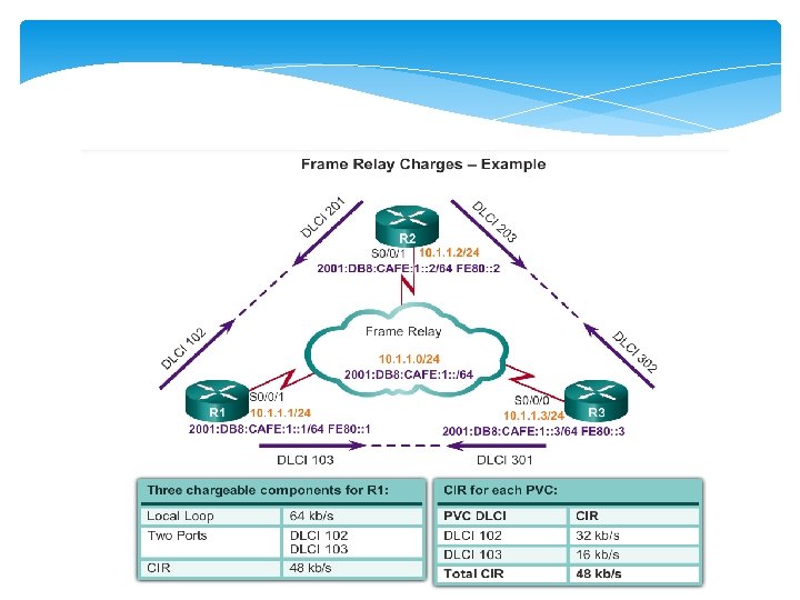
• an access rate on serial port S 0/0/1 of router R 1 to be 64 kb/s. • This is higher than the combined CIRs of the two PVCs. • Under normal circumstances, the two PVCs should not transmit more than 32 kb/s and 16 kb/s, respectively. • As long as the amount of data the two PVCs send does not exceed the CIR, it should get through the network.
Bursting Because the physical circuits of the Frame Relay network are shared between subscribers, there are often times where there is excess bandwidth available. Frame Relay can allow customers to dynamically access this extra bandwidth and burst over their CIR for free. Bursting allows devices that temporarily need additional bandwidth to borrow it at no extra cost from other devices not using it.
• if PVC 102 is transferring a large file, it could use any of the 16 kb/s not being used by PVC 103. • A device can burst up to the access rate and still expect the data to get through. • The duration of a burst transmission should be less than three or four seconds.
Discard Eligible (DE) Bit If the customer sends information faster than the CIR on a given DLCI, the network marks some frames with a Discard Eligibility (DE) bit. The network does its best to deliver all packets; however it discards DE packets first if there is congestion.
Frame Relay Bandwidth Several factors determine the rate at which a customer can send data on a Frame Relay network. Foremost in limiting the maximum transmission rate is the capacity of the local loop to the provider. In Frame Relay terminology, the speed of the local loop is called the local access rate. If the local loop is a T 1, no more than 1. 544 Mbps can be sent.
Frame Relay Bandwidth Providers use the CIR parameter to provision network resources and regulate usage. For example, a company with a T 1 connection to the packet-switched network may agree to a CIR of 768 Kbps. This means that the provider guarantees 768 Kbps of bandwidth to the customer’s link at all times.
Frame Relay Bandwidth If the CIR of the customer is less than the local access rate, the customer and provider agree on whether bursting above the CIR is allowed. Since burst traffic is in excess of the CIR, the provider does not guarantee that it will deliver the frames.
Frame Relay Bandwidth An example is a customer buying a 9. 6 K CIR on a 64 K access line. The customer will be guaranteed 9. 6 K speed but could burst up to 64 K if the need arises, for which he may be charged or frames may be dropped.