Frame Relay Outline Why do we need Frame


 Configure the DLCIs on the all the")
 Setup the VCs")

#encapsulation frame-relay {cisco | ietf} cisco - Default. Use this if")
# interface serial 2/0 R 1(config-if)# ip address 10. 0. 0. 1 255.")


: ip 10. 0. 0. 2 dlci")


- Slides: 54
Frame Relay
Outline Why do we need Frame Relay? Frame Relay Network as a NBMA network Virtual Circuits DLCI Mapping of DLCI Frame Relay Frame
Why do we need Frame Relay? Frame Relay is a more complex technology than point -to-point WAN links but also provides more features and benefits
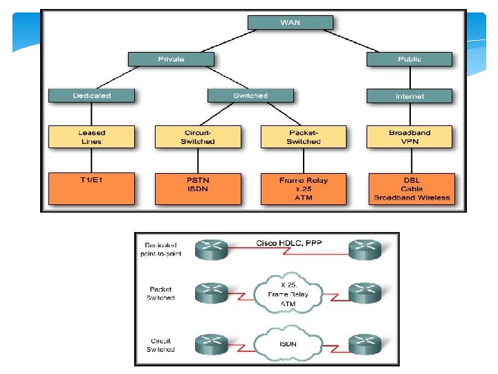
Why do we need Frame Relay? An alternative to dedicated, expensive, leased WAN lines is Frame Relay is a high-performance WAN protocol that operates at the physical and data link layers of the OSI reference model. Frame Relay provides a cost-efficient solution for communications between multiple remote sites by using a single access circuit from each site to the provider.
• The capacity between any two sites can vary.
Frame Relay Network access switches
Frame Relay Network A Frame Relay network is made up of a large number of Frame Relay switches dispersed all over the coverage area of a Frame Relay service provider (e. g. region or country) The switches are interconnected in a complex mesh topology.
Frame Relay Network Frame Relay switches: Terminate user circuits, in addition to connecting to other switches, and are called access switches. Other Frame Relay switches do not terminate user circuits, connecting to other Frame Relay switches only, and make the backbone of the Frame Relay network.
An SVC between the same two DTEs may change. • is temporary connections • is set up dynamically when needed • require call setup and termination for each connection. A PVC between the same two DTEs will always be the same. • A predefined VC. • Is equated to a leased line in concept.
Multiple Virtual Circuits The router or FRAD, connected to the Frame Relay network, may have multiple VCs connecting it to various endpoints.
Multiple Virtual Circuits Multiple VCs on a single physical line are distinguished by assigning each VC an identifier called data-link connection identifiers (DLCI).
DLCI VCs are identified by DLCIs. Frame Relay DLCIs have local significance, that means that their values are unique per router, but not necessarily in the other routers. DLCI values typically are assigned by the Frame Relay service provider.
Frame Relay Switch Frame Relay creates a VC by storing input-port to output-port mapping in the memory of each switch
Frame Relay Address Mapping
Frame Relay Address Mapping Before DLCI can be used to route traffic, it must be associated with the IP address of its remote router
Frame Relay Address Mapping The Head. Quarter will need to map Branch 1 IP address to DLCI 23 & map Branch 2 IP address to DLCI 51. After that it can encapsulate data inside a Frame Relay frame with an appropriate DLCI number and send to the destination.
Mapping of DLCI The mapping of DLCIs to Layer 3 addresses can be handled manually or dynamically. Manually (static): the administrators can statically assign a DLCI to the remote IP address. Dynamic: the router can send an Inverse ARP Request to the other end of the PVC for its Layer 3 address.
Inverse ARP 2 1 Once the router learns from the switch about available PVCs and their corresponding DLCIs, the router can send an Inverse ARP request to the other end of the PVC. (unless statically mapped )
Inverse ARP For each supported and configured protocol on the interface, the router sends an Inverse ARP request for each DLCI. (unless statically mapped) In effect, the Inverse ARP request asks the remote station for its Layer 3 address. At the same time, it provides the remote system with the Layer 3 address of the local system. The return information from the Inverse ARP is then used to build the Frame Relay map.
Now all the routers have a pair of DLCI & IP address of the router at the other end so data can be forwarded to the right destination.
Frame Relay is a data link protocol and the customer router encapsulates each Layer 3 packet inside a Frame Relay frame comprising a header and trailer before it is sent out the access link. The header and trailer used is actually defined by the Link Access Procedure Frame Bearer Services (LAPF) specification
Frame Relay Frame The simple LAPF header was extended to compensate for the absence of a Protocol Type field:
Frame Relay Frame Header DLCI , fields related to congestion management Data – Contains encapsulated upper-layer data Trailer Frame Relay provides no error recovery mechanism. It only provides CRC error detection. You should keep in mind that Frame Relay encapsulation should match on the routers at the two ends of a VC.
Frame Relay Configuration
Outline Building the network and configuring the cloud Basic Frame Relay Configuration Steps Frame Relay Encapsulation Configuring a Static Frame Relay Map
Building the Network
Evaluation
Evaluation
Configuring the cloud ( Frame Relay network) Configure the DLCIs on the all the active serial interfaces of the cloud
Configuring the cloud ( Frame Relay network) Setup the VCs
Basic Frame Relay Configuration Steps
Frame Relay Encapsulation Router(config-if)#encapsulation frame-relay {cisco | ietf} cisco - Default. Use this if connecting to another Cisco router. Ietf Select this if connecting to a non-Cisco router. 33 Rick Graziani graziani@cabrillo. edu
R 1(config)# interface serial 2/0 R 1(config-if)# ip address 10. 0. 0. 1 255. 0. 0. 0 R 1(config-if)# no shutdown R 1(config-if)# encapsulation frame-relay R 2(config)# interface serial 2/0 R 2(config-if)# ip address 10. 0. 0. 2 255. 0. 0. 0 R 2(config-if)# no shutdown R 2(config-if)# encapsulation frame-relay 34
Verifies Frame Relay Configuration
Mapping of DLCI The mapping of DLCIs to Layer 3 addresses can be handled manually or dynamically. Manually (static): the administrators can statically assign a DLCI to the remote IP address. Dynamic: the router can send an Inverse ARP Request to the other end of the PVC for its Layer 3 address.
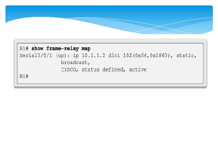
R 1# show frame-relay map Serial 0 (up): ip 10. 0. 0. 2 dlci 102, dynamic, broadcast, status defined, active • dynamic refers to the router learning the IP address via Inverse ARP Rick Graziani graziani@cabrillo. edu 37
Configuring a Static Frame Relay Map
Configuring a Static Frame Relay Map Use the frame-relay map command to configure static address mapping. Once a static map for a given DLCI is configured, Inverse ARP is disabled on that DLCI. The broadcast keyword is commonly used with the frame-relay map command. The broadcast keyword simplifies the configuration of OSPF for nonbroadcast networks that use Frame Relay. 39
Remote IP Address Rick Graziani graziani@cabrillo. edu 40 Local DLCI
Layer 3 Addressing with Frame Relay Cisco's Frame Relay implementation defines three different options for assigning subnets and IP addresses on Frame Relay interfaces: One subnet containing all Frame Relay DTEs One subnet per VC A hybrid of the first two options
One Subnet Containing All Frame Relay DTEs Is the using of a single subnet for the Frame Relay network. The single-subnet option is typically used when a full mesh of VCs exists.
One Subnet Per VC
One Subnet Per VC The single-subnet-per-VC works better with a partially meshed or star Frame Relay network. The single-subnet-per-VC alternative matches the logic behind a set of point-to-point links. Using multiple subnets instead of one larger subnet wastes some IP addresses, but it overcomes some issues with distance vector routing protocols.
Hybrid Approach Routers 1, 2 , and 3 create a smaller full mesh between each other. This allows Routers 1, 2, and 3 to use one subnet. Is treated as a separate subnet
Hybrid Approach We are going to have both point-to-point and multipoint sub-interfaces. Multipoint interfaces are logical Frame Relay subinterfaces but they can terminate more than one PVCs just like physical serial interfaces.
Frame Relay Subinterfaces Frame Relay can partition a physical interface into multiple virtual interfaces called subinterfaces. A subinterface is simply a logical interface that is directly associated with a physical interface. Therefore, a Frame Relay subinterface can be configured for each of the PVCs coming into a physical serial interface.
Frame Relay Subinterfaces Frame Relay subinterfaces can be configured in either point-to-point or multipoint mode:
Point-to-Point Subinterface A single point-to-point subinterface establishes one PVC connection to another physical interface or subinterface on a remote router. In this case, each pair of the point-to-point routers is on its own subnet, and each point-to-point subinterface has a single DLCI. In a point-to-point environment, each subinterface acts like a separate, conventional point-to-point interface.
Multipoint Subinterface A single multipoint subinterface establishes multiple PVC connections to multiple physical interfaces or subinterfaces on remote routers. All the participating interfaces are in the same subnet.
Assigning IP address to point-to-point subinterfacses
Mapping DLCI in point-to-point subinterfacses
Multipoint subinterface