Frame Relay Outline Why do we need Frame


 located within the")
: ◦ Are temporary connections used in situations")
: PVCs are more common. A predefined VC.")


 A star topology, also known as a hub and")


 is a set of enhancements to")


 Bursting Discard Eligible (DE)")


 CAR defines the bandwidth for the virtual circuit guaranteed by")
 CAR is usually lower than the actual access rate of")


 Bit If the customer sends information faster than the CIR on")


- Slides: 64
Frame Relay
Outline Why do we need Frame Relay? Frame Relay Network as a NBMA network Virtual Circuits DLCI Mapping of DLCI Frame Relay Topologies LMI Frame Relay bandwidth
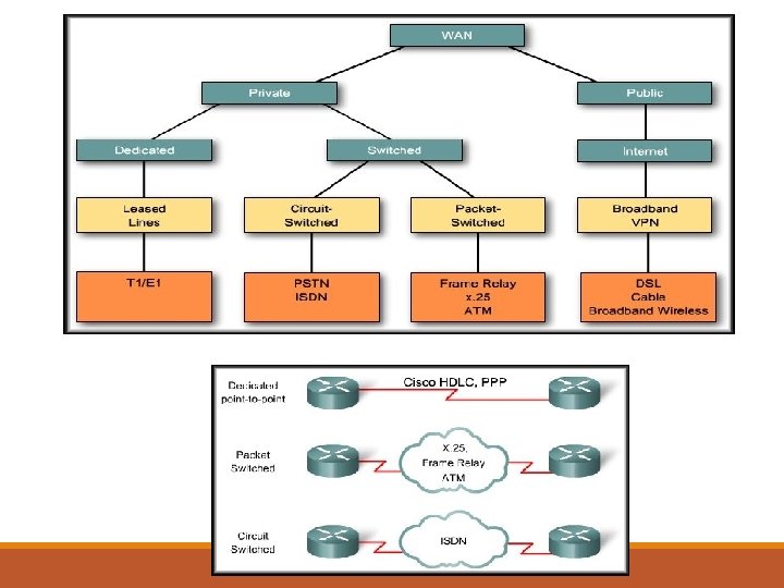
Why do we need Frame Relay? Frame Relay is more complex a technology than point-to-point WAN links but also provides more features and benefits
Why do we need Frame Relay? Leased lines provide permanent dedicated capacity and are used extensively for building WANs. Disadvantages ◦ A fixed capacity (WAN traffic is often variable) ◦ Equipment costs An alternative to dedicated, expensive, leased WAN lines is Frame Relay is a high-performance WAN protocol that operates at the physical and data link layers of the OSI reference model. Frame Relay provides a cost-efficient solution for communications between multiple remote sites by using a single access circuit from each site to the provider.
• The capacity between any two sites can vary.
Frame Relay Network access switches
Frame Relay Network A Frame Relay network is made up of a large number of Frame Relay switches dispersed all over the coverage area of a Frame Relay service provider (e. g. region or country) The switches are interconnected in a complex mesh topology. Frame Relay switches: ◦ Terminate user circuits, in addition to connecting to other switches, and are called access switches. ◦ Other Frame Relay switches do not terminate user circuits, connecting to other Frame Relay switches only, and make the backbone of the Frame Relay network.
Broadcast Multi. Access networks vs. NBMA network On a broadcast network, multiple devices are attached to a shared network. When one device transmits frames, all nodes on the network "listen" to the frames, but only the node to which the frames are addressed actually receives the frames. Thus, the frames are broadcast. On a nonbroadcast network multiple devices are attached, but data is transmitted directly from one computer to another over a virtual circuit or across a switching fabric. (e. g. ATM , frame relay, and X. 25).
Frame Relay Network as a NBMA network Frame Relay networks are multiaccess networks, which means that more than two devices can connect to the network. Unlike with LANs, Frame Relay cannot send a data as a broadcast. Therefore, Frame Relay networks are called nonbroadcast multiaccess (NBMA) networks.
DCE & DTE In the context of Frame Relay: ◦ the DTE is the router or sometimes Frame Relay Access Devices (FRADs). ◦ The DCE is Frame Relay switch. ◦ The purpose of DCE equipment is to provide clocking and switching services in a network
Frame Relay Network The Frame Relay network is not like the Internet where any two devices connected to the Internet can communicate. In a Frame Relay network, before two routers can exchange information, a virtual circuit between them must be set up ahead of time by the Frame Relay service provider.
Virtual Circuits The connection through a Frame Relay network between two DTEs is a virtual circuit (VC). VC is a means of transporting data over a packet switched network in such a way that it appears as though there is a dedicated physical layer link between the 2 DTEs.
CH 1
A VC can pass through any number of intermediate devices (switches) located within the Frame Relay network The circuits are virtual because there is no direct electrical connection from end to end. • Provides connection-oriented data link layer communication • A logical connection between two DTE across a Frame Relay packet-switched network • Provide a bi-directional communications path from one DTE device to another Frame Relay is a packet-switched, connection-oriented, WAN service.
VC Types 1. Switched virtual circuits (SVCs): ◦ Are temporary connections used in situations requiring only sporadic data transfer between DTE devices across the Frame Relay network. ◦ SVC is set up dynamically when needed. ◦ SVC connections require call setup and termination for each connection. ◦ SVCs are not very common
VC Types 2. Permanent virtual circuits (PVCs): PVCs are more common. A predefined VC. ◦ Used for frequent and consistent data transfers between DTEs devices across the Frame Relay network. A PVC can be equated to a leased line in concept. The switching information for a VC is stored in the memory of the switch.
An SVC between the same two DTEs may change. Path may change. A PVC between the same two DTEs will always be the same. Always same Path.
Multiple Virtual Circuits The router or FRAD, connected to the Frame Relay network, may have multiple VCs connecting it to various endpoints.
DLCI Multiple VCs on a single physical line are distinguished by assigning each VC an identifier called data-link connection identifiers (DLCI). Frame Relay DLCIs have local significance, that means that their values are unique per router, but not necessarily in the other routers. DLCI values typically are assigned by the Frame Relay service provider.
Frame Relay Switch Frame Relay creates a VC by storing input-port to output-port mapping in the memory of each switch and thus links one switch to another until a continuous path from one end of the circuit to the other is identified.
DLCI
Frame Relay Address Mapping
Frame Relay Address Mapping Before DLCI can be used to route traffic, it must be associated with the IP address of its remote router
Frame Relay Address Mapping The Head. Quarter will need to map Branch 1 IP address to DLCI 23 & map Branch 2 IP address to DLCI 51. After that it can encapsulate data inside a Frame Relay frame with an appropriate DLCI number and send to the destination.
Mapping of DLCI The mapping of DLCIs to Layer 3 addresses can be handled manually or dynamically. Manually (static): the administrators can statically assign a DLCI to the remote IP address. Dynamic: the router can send an Inverse ARP Request to the other end of the PVC for its Layer 3 address.
Inverse ARP 2 1 Once the router learns from the switch about available PVCs and their corresponding DLCIs, the router can send an Inverse ARP request to the other end of the PVC. (unless statically mapped )
Inverse ARP For each supported and configured protocol on the interface, the router sends an Inverse ARP request for each DLCI. (unless statically mapped) In effect, the Inverse ARP request asks the remote station for its Layer 3 address. At the same time, it provides the remote system with the Layer 3 address of the local system. The return information from the Inverse ARP is then used to build the Frame Relay map.
Now all the routers have a pair of DLCI & IP address of the router at the other end so data can be forwarded to the right destination.
Frame Relay is a data link protocol and the customer router encapsulates each Layer 3 packet inside a Frame Relay frame comprising a header and trailer before it is sent out the access link. The header and trailer used is actually defined by the Link Access Procedure Frame Bearer Services (LAPF) specification
Frame Relay Frame The simple LAPF header was extended to compensate for the absence of a Protocol Type field:
Frame Relay Frame Header ◦ DLCI , ◦ fields related to congestion management Data – Contains encapsulated upper-layer data Trailer ◦ Frame Relay provides no error recovery mechanism. It only provides CRC error detection. You should keep in mind that Frame Relay encapsulation should match on the routers at the two ends of a VC.
Frame Relay Topologies ◦ When more than two sites must be connected, the Frame Relay topology, or map, of the connections between the sites must be planned. ◦ Every network can be viewed as being one of three topology types:
Star Topology (Hub and Spoke) A star topology, also known as a hub and spoke configuration, is the most popular Frame Relay network topology because it is the most cost -effective. Spoke Hub
Each remote site has an access link to the Frame Relay cloud with a single VC. The hub at has an access link with multiple VCs, one for each remote site. Because Frame Relay costs are not distance-related, the hub does not need to be in the geographical center of the network.
Full-Mesh Topology A full-mesh topology suits a situation in which the services to be accessed are geographically dispersed and highly reliable access to them is required. A full-mesh topology connects every site to every other site More costly than hub and spoke, provides direct connections from each site to all other sites and allows for redundancy used four VCs on each link
Partial-Mesh Topology Full Mesh Topology Number of Connections PVCs ---------------2 1 4 6 6 15 8 28 10 45 For large networks, a full-mesh topology is seldom affordable because the number of links required increases dramatically. The issue is not with the cost of the hardware, but because there is a theoretical limit of fewer than 1000 VCs per link. In practice, the limit is less than that.
Partial-Mesh Topology For this reason, larger networks generally are configured in a partialmesh topology. Partial mesh has more interconnections than are required for a star arrangement, but not as many as for a full mesh. The actual pattern depends on the data flow requirements.
LMI Frame Relay bandwidth
LMI The Local Management Interface ( LMI ) is a set of enhancements to the basic Frame Relay specification. It offers a number of features (called extensions) for managing complex internetworks.
LMI Extensions LMI provides a signaling or diagnostic between the DTE router and the Frame Relay switch, using several types of messages: ◦ Virtual circuit status messages ◦ Global addressing messages ◦ Multicasting messages
LMI Extensions VC status messages Provide information about PVC integrity by communicating between devices, periodically reporting the existence of new PVCs and the deletion of already existing PVCs. VC status messages prevent data from being sent into black holes (PVCs that no longer exist). The Status-enquiry messages ◦ from the router to the switch ◦ sent every 10 seconds ◦ allow the router to ask about the status of network. The Status messages ◦ from the switch to the router ◦ responding to status-enquiry messages. ◦ signal if a PVC is active or inactive.
LMI Extensions VC status messages These periodic LMI messages also serve as keepalives for both the router and the switch. If the access link is having a problem, these keepalives will be missed and link problem will be detected. LMI status messages act as a keepalive between the DTE and DCE
LMI Extensions VC status messages LMI status messages combined with Inverse ARP messages allow a router to associate network layer and DCLI.
LMI Extensions Multicasting messages ◦ The multicasting extension defines multicasting as another optional LMI feature. Allows a sender to transmit a single frame that is delivered to multiple recipients. There is a series of four reserved DLCI values (1019 to 1022) that represent multicast groups.
LMI Extensions Global addressing messages In the basic Frame Relay specification, DLCI values are locally significant and Frame Relay addresses do not exist. Therefore, mapping must be created. ◦ The global addressing extension solves this problem by allowing DLCI values that are globally significant and hence can serve as addresses of individual end routers. ◦ The Frame Relay network with global addressing looks much like a LAN to the end routers that can use global addresses (DLCIs) as Frame Relay addresses similar to MAC addresses used in a LAN.
LMI Identifier LMI is used to manage Frame Relay links. Each LMI message is classified by a DLCI appearing in the LMI frame.
LMI Identifier The 10 -bit DLCI field supports 1, 024 VC IDs: 0 to 1, 023. The LMI extensions reserve some of these VC IDs, thereby reducing the number of permitted VCs. LMI messages are exchanged between the DTE and DCE using these reserved DLCIs.
LMI Types There are several LMI types, each of which is incompatible with the others. ◦ CISCO - Original LMI extension ◦ ANSI - Corresponding to the ANSI standard T 1. 617 Annex D ◦ Q 933 A - Corresponding to the ITU standard Q 933 Annex A The LMI type configured on the router must match the type used by the service provider.
Frame Relay Bandwidth Local Access Rate Committed Access Rate (CAR) Bursting Discard Eligible (DE) Bit
Local Access Rate This is the clock speed or port speed of the access link or local loop to the Frame Relay cloud. It is the maximum transfer rate at which data travels into or out of the network, regardless of other settings
Local Access Rate The service provider provides a serial connection or access link to the Frame Relay network with specific rate (the access rate) These may be 56 kb/s, T 1 (1. 544 Mb/s), or Fractional T 1 (a multiple of 56 kb/s or 64 kb/s). Access rates are clocked on the Frame Relay switch. It is not possible to send data at higher than the access rate.
Committed Access Rate (CAR) CAR defines the bandwidth for the virtual circuit guaranteed by the service provider under normal conditions. The CAR is the amount of data that the network receives from the access circuit. The service provider guarantees that the customer can send data at the CAR. All frames received at or below the CAR are accepted.
Committed Access Rate (CAR) CAR is usually lower than the actual access rate of the interface. Customers can choose the CAR that is most appropriate to their bandwidth needs, as long as the CAR is less than or equal to the local access rate. Typically, the higher the CAR, the higher the cost of service.
Bursting A great advantage of Frame Relay is that any network capacity that is being unused is made available or shared with all customers, usually at no extra charge. This allows customers to burst over their CIR as a bonus.
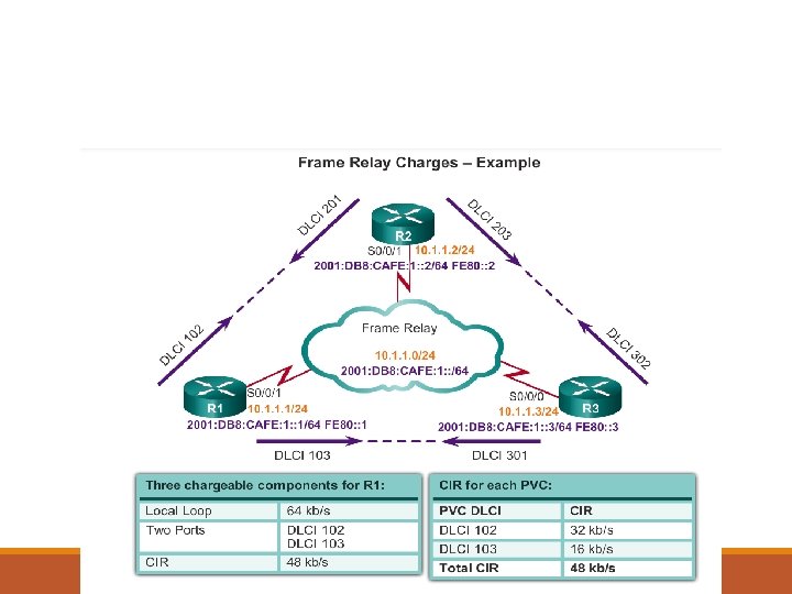
• an access rate on serial port S 0/0/1 of router R 1 to be 64 kb/s. • This is higher than the combined CIRs of the two PVCs. • Under normal circumstances, the two PVCs should not transmit more than 32 kb/s and 16 kb/s, respectively. • As long as the amount of data the two PVCs send does not exceed the CIR, it should get through the network.
Bursting Because the physical circuits of the Frame Relay network are shared between subscribers, there are often times where there is excess bandwidth available. Frame Relay can allow customers to dynamically access this extra bandwidth and burst over their CIR for free. Bursting allows devices that temporarily need additional bandwidth to borrow it at no extra cost from other devices not using it.
• if PVC 102 is transferring a large file, it could use any of the 16 kb/s not being used by PVC 103. • A device can burst up to the access rate and still expect the data to get through. • The duration of a burst transmission should be less than three or four seconds.
Discard Eligible (DE) Bit If the customer sends information faster than the CIR on a given DLCI, the network marks some frames with a Discard Eligibility (DE) bit. The network does its best to deliver all packets; however it discards DE packets first if there is congestion.
Frame Relay Bandwidth Several factors determine the rate at which a customer can send data on a Frame Relay network. Foremost in limiting the maximum transmission rate is the capacity of the local loop to the provider. In Frame Relay terminology, the speed of the local loop is called the local access rate. If the local loop is a T 1, no more than 1. 544 Mbps can be sent.
Frame Relay Bandwidth Providers use the CIR parameter to provision network resources and regulate usage. For example, a company with a T 1 connection to the packet-switched network may agree to a CIR of 768 Kbps. This means that the provider guarantees 768 Kbps of bandwidth to the customer’s link at all times.
Frame Relay Bandwidth If the CIR of the customer is less than the local access rate, the customer and provider agree on whether bursting above the CIR is allowed. Since burst traffic is in excess of the CIR, the provider does not guarantee that it will deliver the frames.
Frame Relay Bandwidth An example is a customer buying a 9. 6 K CIR on a 64 K access line. The customer will be guaranteed 9. 6 K speed but could burst up to 64 K if the need arises, for which he may be charged or frames may be dropped.