Electrical Analogy of Heat Transfer P M V


:")


- Slides: 29
Electrical Analogy of Heat Transfer P M V Subbarao Associate Professor Mechanical Engineering Department IIT Delhi Simple ideas to Eliminate Discontinuities in Solution Domain…
Discontinuous Conduction Medium
Discontinuous Conduction Medium • High strength metal structures are required for tall buildings. • The partition wall materials should be light and insulating. • This generates a composite wall with sudden change in thermal conductivity with heat flow direction. • Introduces a discontinuity in the solution domain. • Develop a simple method to avoid singularities. TInterior TExterior
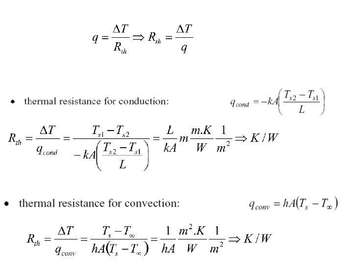
Electrical Circuit Theory of Heat Transfer • Define. Thermal Resistance • A resistance can be defined as the ratio of a driving potential to a corresponding transfer rate. Analogy: Electrical resistance is to conduction of electricity as thermal resistance is to conduction of heat. The analog of Q is current, and the analog of the temperature difference, T 1 - T 2, is voltage difference. From this perspective the slab is a pure resistance to heat transfer and we can define
The composite Wall • The concept of a thermal resistance circuit allows ready analysis of problems such as a composite slab (composite planar heat transfer surface). • In the composite slab, the heat flux is constant with x. • The resistances are in series and sum to Rth = Rth 1 + Rth 2. • If TL is the temperature at the left, and TR is the temperature at the right, the heat transfer rate is given by
Wall Surfaces with Convection Boundary conditions: T 1 T 2 Rconv, 1 Rcond Rconv, 2
Heat transfer for a wall with dissimilar materials Heat Transfer Circuit • For this situation, the total heat flux Q is made up of the heat flux in the two parallel paths: • Q = Q 1+ Q 2 • with the total resistance given by:
Composite Walls • The overall thermal resistance is given by
Desert Housing & Composite Walls Rconv, room Rcond 1 Rcond 2 Rcond 3 Rcond 4 Rconv, amb
One-dimensional Steady Conduction in Radial Systems Homogeneous and constant property material
At any radial location the surface are for heat conduction in a solid cylinder is: At any radial location the surface are for heat conduction in a solid sphere is: The GDE for cylinder:
The GDE for sphere: General Solution for Cylinder: General Solution for Sphere:
Boundary Conditions • No solution exists when r = 0. • Totally solid cylinder or Sphere have no physical relevance! • Inner wall at finite radius is essential for steady state conduction with no heat generation. • Dirichlet Boundary Conditions: The boundary conditions in any heat transfer simulation are expressed in terms of the temperature at the boundary. • Neumann Boundary Conditions: The boundary conditions in any heat transfer simulation are expressed in terms of the temperature gradient at the boundary. • Mixed Boundary Conditions: A mixed boundary condition gives information about both the values of a temperature and the values of its derivative on the boundary of the domain. • Mixed boundary conditions are a combination of Dirichlet boundary conditions and Neumann boundary conditions.
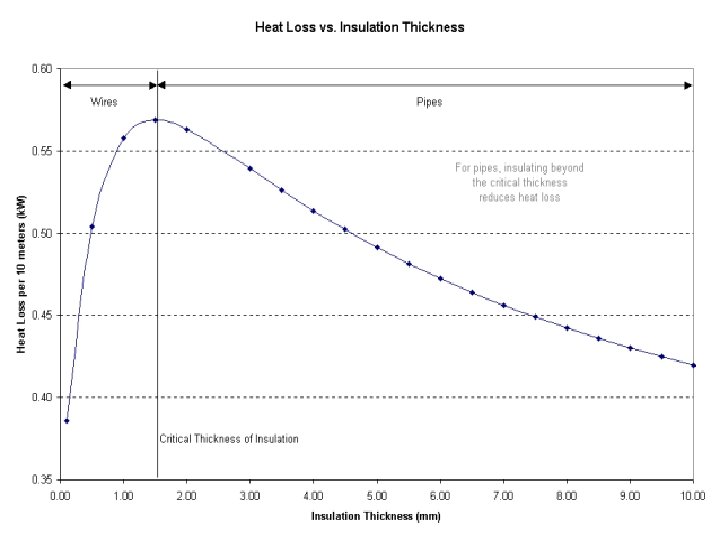
Mean Critical Thickness of Insulation Heat loss from a pipe surface: h, T • If A, is increased, Q will increase. • When insulation is added to a pipe, the outside surface area of the pipe will increase. • This would indicate an increased rate of heat transfer ri Ts ro • The insulation material has a low thermal conductivity, it reduces the conductive heat transfer lowers the temperature difference between the outer surface temperature of the insulation and the surrounding bulk fluid temperature. • This contradiction indicates that there must be a critical thickness of insulation. • The thickness of insulation must be greater than the critical thickness, so that the rate of heat loss is reduced as desired.
Electrical analogy: As the outside radius, ro, increases, then in the denominator, the first term increases but the second term decreases. Thus, there must be a critical radius, rc , that will allow maximum rate of heat transfer, Q The critical radius, rc, can be obtained by differentiating and setting the resulting equation equal to zero.
Only the term which can be made to zero is: The critical value of outer radius, ro = rc is
Maximum Rate of Heat Transfer (Loss):
Safety of Insulation • Hot fluid carrying pipes that are readily accessible by workers are subject to safety constraints. • The recommended safe "touch" temperature range is from 54. 4 0 C to 65. 5 0 C. • Insulation calculations should aim to keep the outside temperature of the insulation around 60 0 C. • An additional tool employed to help meet this goal is aluminum covering wrapped around the outside of the insulation. • Aluminum's thermal conductivity of 209 W/m K does not offer much resistance to heat transfer, but it does act as another resistance while also holding the insulation in place. • Typical thickness of aluminum used for this purpose ranges from 0. 2 mm to 0. 4 mm. • The addition of aluminum adds another resistance term, when calculating the total heat loss:
Structure of Hot Fluid Piping T 1 T 2 Rconv, 1 Rpipe Rinsulation RAl Rconv, 2
• However, when considering safety, engineers need a quick way to calculate the surface temperature that will come into contact with the workers. • This can be done with equations or the use of charts. • We start by looking at diagram:
At steady state, the heat transfer rate will be the same for each layer:
Solving the three expressions for the temperature difference yields: Each term in the denominator of above Equation is referred to as the “Thermal resistance" of each layer.
Design Procedure • Use the economic thickness of your insulation as a basis for your calculation. • After all, if the most affordable layer of insulation is safe, that's the one you'd want to use. • Since the heat loss is constant for each layer, calculate Q from the bare pipe. • Then solve T 4 (surface temperature). • If the economic thickness results in too high a surface temperature, repeat the calculation by increasing the insulation thickness by 12 mm each time until a safe touch temperature is reached. • Using heat balance equations is certainly a valid means of estimating surface temperatures, but it may not always be the fastest. • Charts are available that utilize a characteristic called "equivalent thickness" to simplify the heat balance equations. • This correlation also uses the surface resistance of the outer covering of the pipe.
Further Mathematical Analysis : Homogeneous ODE • How to obtain a non-homogeneous ODE for one dimensional Steady State Heat Conduction problems? • Blending of Convection or radiation effects into Conduction model. • Generation of Thermal Energy in a solid body. • GARDNER-MURRAY Ideas.
Mathematical Ideas are More Natural An optimum body size is essential for the ability to regulate body temperature by blood-borne heat exchange. For animals in air, this optimum size is a little over 5 kg. For animals living in water, the optimum size is much larger, on the order of 100 kg or so. This may explain why large reptiles today are largely aquatic and terrestrial reptiles are smaller.
Mathematical Ideas are More Natural • Reptiles like high steady body temperatures just as mammals and birds. • They have sophisticated ways to manage flows of heat between their bodies and the environment. • One common way they do this is to use blood flow within the body to facilitate heat uptake and retard heat loss. • Blood flow is not effective as a medium of heat transfer everywhere in the body. • Body shape also enters into the equation. • It also helps expalin the odd appendages like crests and sails that decorated extinct reptiles like Stegosaurus or mammal-like reptiles like Dimetrodon. • Theoretical Biologists did Calculations to show these structures could act as very effective heat exchange fins, allowing animals with crests to heat their bodies up to high temperatures much faster than animals without them.