DPT 321 INJECTION MOLD DESIGN School of Manufacturing


- Slides: 21

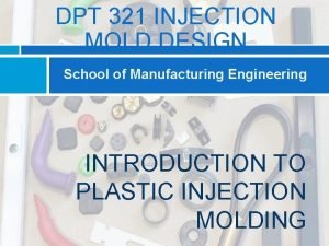
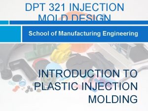
DPT 321 INJECTION MOLD DESIGN School of Manufacturing Engineering INTRODUCTION TO PLASTIC INJECTION MOLDING

COURSE CONTENT & COURSE OUTCOMES COURSE CONTENT Chapter 1: Introduction to Plastic Injection Molding DEFINE, DESCRIBE and EXPLAIN the injection molding process, injection molding machine, injection molding cycle, mold structures, and types of mold. COURSE OUTCOMES CO 1: Ability to define and describe basic terminology process in plastic injection molding, mold design and part design. DPT 321 INJECTION MOLD DESIGN

DPT 321 INJECTION MOLD DESIGN MOLDING MACHINE SIZE

MOLDING MACHINE SIZE Ø Determination of the appropriate size of an injection molding machine is based primarily on the required clamp force which depends on: q the projected area of the cavities in the mold q the maximum pressure in the mold during mold filling Ø The projected area of the cavity is actually the projected area of the part, or parts if a multi-cavity mold is used, and a runner system, when viewed in the direction of mould opening The value should not include any through holes molded in the direction of mould opening

MOLDING MACHINE SIZE (Projected Area) Ø Example-1: q For a 20 cm diameter plain disk, the projected area is 314. 16 cm 2. However, if the disk has a single 10 cm diameter through hole in any position, what is the actual projected area? .

MOLDING MACHINE SIZE Ø ANSWER (Example - 1: )

MOLDING MACHINE SIZE Ø The size of the runner system depends on the size of the part. Typical runner volumes as a percentage of part volume are given as :

MOLDING MACHINE SIZE Ø Related table to calculated Molding Machine Size :

MOLDING MACHINE SIZE Ø Related table to calculated Moulding Machine Size :

MOLDING MACHINE SIZE Ø As a general rule, approximately 50% of the pressure generated in the machine injection unit is lost due to the flow resistance in the sprue, runner systems and gates Ø Example 2: q A batch of 10 cm diameter disk with a thickness of 8 mm are to be molded from high-density polyethylene (PE) in a 6 -cavity mold. Determine the appropriate machine size? . (Given that, approximately 50% of the pressure generated in the machine injection unit is lost)

MOULDING MACHINE SIZE

DPT 321 INJECTION MOLD DESIGN MOLDING CYCLE TIME

MOLDING CYCLE TIME Ø Define as time taken to produce 1 unit product started from injection until ejection and resetting Ø Consist from 3 stages : FILLING+PACKING COOLING EJECTION /RESETTING MOULDING CYCLE

MOLDING CYCLE TIME Ø After the appropriate machine size for a particular molded part has been established, the molding cycle time can be estimated i. Injection Time • A total time requires for polymer to flow through the runners, gates and fulfil the cavity passages.

MOLDING CYCLE TIME Ø Injection time (filling time) is given by: sec Where: Vs = required shot size (amount of material) m 3 pj = recommended injection pressure N/m 2 (table-8. 5) Pj = injection power W (table-8. 4)

MOLDING CYCLE TIME Ø Example 3: q Calculate the estimated injection time for the 10 cm disks molded in a 6 -cavity mold as in Example 2.

MOLDING CYCLE TIME Refer Table 8. 4 for Injection Power, Pj and Table 8. 5 for Injection Pressure, pj

MOLDING CYCLE TIME ii. Cooling Time q It is assumed that cooling in the mould takes place almost entirely by heat conduction Ø Cooling time is given by: Where: hmax = maximum wall thickness mm Tx = recommended part ejection temperature Tm = recommended mould temperature o. C Ti = recommended injection temperature o. C a = thermal diffusivity coefficient mm 2/s o. C TABLE – 8. 5

MOLDING CYCLE TIME iii. Resetting Time q The summation of mould opening, part ejection and mould closing times is referred to as the resetting time and have been suggested by Ostwald as:

MOLDING CYCLE TIME Ø Mold resetting time is given by: sec Where: td = dry cycle time sec Ls = maximum clamp stroke cm D = depth of part to be moulded cm TABLE – 8. 4

MOLDING CYCLE TIME Ø Example 4: q Assume that 10 cm diameter plain cylindrical cups with a depth of 8 cm (high-density polyethylene ) are to be moulded in a sixcavity mould. Calculate the mould resetting time. Ø Answer 4:
 Protista unicellular or multicellular
 Bulk factor in compression moulding
 Pot type mold & plunger type mold are the classification of
 Cold slug well injection molding
 Importance of ndt
 Dpt psychology
 Dpt 110
 Dpt 110
 Oasif
Oasif Psychrometry is the study of
 Vcu dpt
 Manufacturing cost vs non manufacturing cost
 Job vs process costing
 Cost concept and classification
 Manufacturing cost vs non manufacturing cost
 Additive manufacturing vs subtractive manufacturing
 How to calculate projected area injection molding
 Edel 321
 Responsibilities
 Csi 321
 123 132 213 231 312 321
 Apokalypsis 321
