DEVELOPMENTS IN SUPERCONDUCTING CYCLOTRON AT VECC M K


")


 Blue: -6 deg rot Green:")


 lesser large energy")


 Keeping Energy Gain Per Turn Same")
 Effect on Beam Phase")

 Effect on Coherent Oscillation Amplitude Red (AEO) Blue Magenda")


- Slides: 68
DEVELOPMENTS IN SUPERCONDUCTING CYCLOTRON AT VECC M. K. Dey on behalf of Superconducting Cyclotron Project Team UFCYC, 28 th June 2012
CONTENT 1. Developments / improvements of various systems 2. Observations during beam extraction trial 3. Understanding of beam behavior
Superconducting Cyclotron at VECC
Deflector-2 Bore Probe 153° M-1 Deflector-1 Extraction Beam line Main Probe 249°
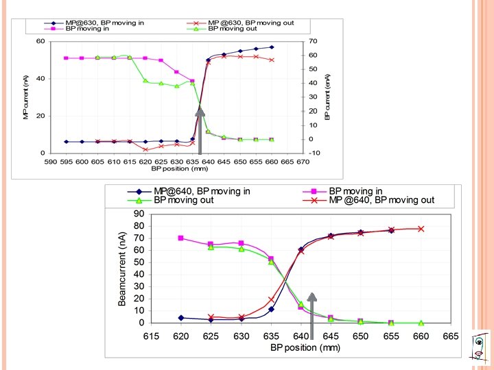
BEAM DROPS SHARPLY AT ~665 MM RADIUS DEFLECTOR ENTRY POSITION (667 MM 674 MM)
GRADUAL FALL IN SOME OTHER SETTINGS
BEAM EXTRACTION TRIAL Different configurations of central region electrode gaps Rotation Vertical of spiral inflector movement of spiral inflector
DIFFERENT CONFIGURATION OF CENTRAL REGION GEOMETRY Dee-1 Dee-2 Dee-3
ROTATION OF INFLECTOR
Effect of inflector housing rotation Solid Red: 0 deg) Blue: -6 deg rot Green: +6 deg rot Vdee = 28 k. V
MOVING DEE CONNECTORS INSIDE A B C Dee A: shifted in 1. 5 mm Dee C: shifted in 2 mm
Effect of moving the dee connectors Original : Magenta Shifted : Black Dee voltage: 30 k. V
BEAM EXTRACTION TRIAL Deflector in Faraday cup mode Additional probe at the Deflector-1 entry and exit Capturing beam trace on film
Beam Extraction Trials
BEAM EXTRACTION TRIAL Measurement of beam centering by shadowing method with two probes Beam phase measurement
Orbit Centering Measurement by Shadowing Method Using Main probe and Bore Probe Data taken on 15/08/2011, Shift-III
Data taken on 14 Aug 2011
BEAM PHASE MEASUREMENT Method: • Using Trim coils beam current is reduced to half intensity at different radii • Driving the central phase to +/- 90 deg. • Change of phase, i. e. Δ Sin(φ), is calculated using the change in current setting • Sin(φ)reference= Δ Sin(φ) ± 1
BEAM PHASE MEASUREMENT Garren and Smith Method Field Detuning: Frequency Detuning:
Beam Current vs Radius Plots
BEAM PHASE AT INNER RADII
BEAM PHASE AT EXTRACTION ZONE
Phase Correction by Shimming
IMPROVEMENTS OF VARIOUS SYSTEMS Improvement RF of RF phase stability conditioning by pulsing technique Reduced conditioning time Improvement Dee in Dee voltage measurement by X-ray method
Dee Voltage Measurements
NEW DESIGN OF SPIRAL INFLECTOR Better mechanical stability Large electrode width Wider good field region
IMPROVEMENT OF BEAM DIAGNOSTICS Main probe moving on one hill central line Boroscope To probe with Zn. S plate see the beam spot Sometimes Magnetic fitted with current measuring head channel 1
IMPROVEMENT OF BEAM DIAGNOSTICS Deflector 1 exit plate Deflector can be insulated to read current C-probe – To see the vertical blow-up of the beam (resonance effect) Delta-r probe
Understanding of Beam Behavior
BEAM BEHAVIOR Asymmetric dee voltages possibly balance the magnetic field imperfections Inherent magnetic field imperfection increases at outer radii beam off-centering, resonances Deflector geometry and position may not be matching with beam trajectory
BEAM BEHAVIOR Beam rises High phase sharply at the extraction region dee votage
BEAM BEHAVIOR Wrong beam phase w. r. t. RF (? ) lesser large energy gain per turn, number of turns So field errors will have larger effect sharper larger phase slip off-centering slower crossing of resonance zones and hence beam blow up Higher Dee voltage helps to overcome these effects, so that beam survives till outer radii
Static Equilibrium Orbit and Accelerated Orbits Radial displacement and conjugate momentum Gap-2 Gap-3 Gap-4 Gap-1 Equation of motion Gap-5 Gap-6
Accelerated Equilibrium Orbit and Coherent Radial Oscillation Red: AEO, 89 turns, r = 2. 15” to 16. 79”, E/A=0. 030 Me. V/A to 1. 95 Me. V/A Blue: Coherent Oscillation, 91 turns, r = 1. 8” to 16. 86”, E/A=0. 030 Me. V/A to 1. 969 Me. V/A
Phase points for AEO and another accelerated orbit Throughout the acceleration zone RED: AEO Turn Gap θ r (inch) pr (inch) ϕ ° 207 1. 5 305. 146 26. 61913 -. 03425 50. 328 E (Mev/A) τ 4. 491568 50. 328 ϕ ° (GAV) x (inch) Px (inch) 41. 645. 19646. 00650 Blue: Orbit oscillating around AEO Turn Gap θ r (inch) pr (inch) ϕ ° 192 1. 5 305. 827 26. 31017 -. 50581 -39. 854 E (Mev/A) τ ϕ ° (GAV) x (inch) Px (inch) 4. 037386 320. 146 -34. 796 2. 12835 -. 56712
Coherent Radial Oscillation And Orbit Centering Initial conditions: Turn Gap 0 1. 5 θ r (inch) pr (inch) 52. 067 2. 15000 0. 15000 52. 067 1. 80000 -. 04000 52. 067 1. 80000. 05000 Turn Gap θ r (inch) pr (inch) 190 1. 5 321. 563 22. 33461 -1. 05346 ϕ° 6. 827 E (Mev/A) 4. 074939 ϕ° . 000 E (Mev/A) . 030000 Red Blue Black τ ϕ ° (GAV) x (inch) Px (inch) 6. 827 -28. 180 1. 98568 -1. 10329
Instantaneous Radial Position and Momentum
Effect of Coherent Oscillation on Phase at Sprial Central Line of Dee-1
Phase at Sprial Central Line of Dee-1 Averaged over 2 Ndee Gaps
Effect of Coherent Oscillation on Energy Gain Energy Vs Instantaneous Radial Position along Central Line of Dee-1
Accelerated Equilibrium Orbit Bore Probe Dee-1 Exit Dee-1 Centre Line Main Probe Dee-1 Entry
Orbit Oscillating around AEO: may not match Deflector -2 Bore Probe Deflector -1 Dee-1 Exit Dee-1 Centre Line Main Probe Dee-1 Entry
Oscillating Orbit: moving away from Deflector -2 Bore Probe Deflector -1 Main Probe
Precision of orbit in the extraction zone
Effect of Asymmetric Dee Voltages (5%) Keeping Energy Gain Per Turn Same
Asymmetric Dee Voltages (5%) Effect on Beam Phase
Effect on Beam Phase Larger phase excursion
Asymmetric Dee Voltages (5%, 8%) Effect on Coherent Oscillation Amplitude Red (AEO) Blue Magenda Vdee-1 1. 05 1. 08 Vdee-2 1. 0 Vdee-3 1. 0 0. 95 0. 92
Controlling Beam Centering with Asymmetric Dee Voltages First 40 Turns ~0. 9 Me. V/A Black (AEO) Red Blue Magenda Vdee-1 1. 0 0. 95 1. 0 Vdee-2 1. 0 0. 95 1. 05 Vdee-3 1. 05 1. 0 0. 95
Higher Dee Voltage Requirement? Red: Vdee=30 k. V Blue: Vdee=35 k. V Magenda: Vdee=40 k. V
Beam Current Vs. Dee Voltage VB & VC fixed, VA Varying
VA & VC fixed, VB Varying
VA & VB fixed, VC Varying
Particles with different starting phase 200°, 205°, 210°, 215°, 220°, 225°
Effect of Asymmetric Dee Voltage on central region orbits 10% asymmetric Blue Red Vdee-1 1. 0 1. 1 Vdee-2 1. 0 Vdee-3 1. 0 0. 9
Effect of Asymmetric Dee Voltage on central region orbits 20% asymmetric Vdee-1 Blue 1. 0 Red 1. 1 Magenda 1. 2 Vdee-2 1. 0 Vdee-3 1. 0 0. 9 0. 8
Magnetic Field Imperfections
Effect of first harmonic imperfection on the orbits
Effect of first harmonic field imperfection on beam phase Appreciable effect at Extraction zone
Effect of first harmonic field imperfection Coherent Radial Oscillation
Compensation of Coherent Radial Oscillation Applying Asymmetric Dee Voltage 3% Asymmetric Dee voltage scaling factor for A, B, C respectively 1. 03, 1. 0, 0. 97
Compensation of Coherent Radial Oscillation Applying Asymmetric Dee Voltage 4% Asymmetric Dee voltage scaling factor for A, B, C respectively 1. 04, 1. 0, 0. 96
Compensation of Coherent Radial Oscillation Applying Asymmetric Dee Voltage 5% Asymmetric Dee voltage scaling factor for A, B, C respectively 1. 05, 1. 0, 0. 95
Over Compensation…. Dee voltage scaling factor for A, B, C respectively 1. 02, 0. 97
Conclusion: • Coherent Radial Oscillation affect beam phase, energy gain, cause orbit precession at the extraction zone • Asymmetric Dee voltage cause coherent oscillation at extraction zone • Asymmetric Dee voltage has negligible effect on first turn
Conclusion: • Magnetic imperfection cause coherent oscillation and orbit precession at extraction zone • Asymmetric dee voltage can be used to compensate the magnetic field imperfection effect • Asymmetric dee voltage can be used to control beam centering
THANKS