DESIGN OF ELECTRICAL MACHINES EE 6604 FACULY NAME


 © To design the electrical machines properly, one should be familiar with")


 : range and method")


 Should not consume any power or should have a low dielectric ©")


 Common factors affect the choice of SML are;")


 Common factors affect the choice of SEL are;")


, ds and δ are fixed,")


 • The motor is")


- Slides: 82
DESIGN OF ELECTRICAL MACHINES EE 6604 FACULY NAME SHRI. N. B. RAJESH M. E. AP-II/EEED VCET, Madurai
DESIGN OF ELECTRICAL MACHINES Aim: © The aim of the design is to completely obtain the dimensions of all the parts of the machine to furnish the data to the manufacturer. © The main aim of carrying out the design is to achieve the following: u Lower cost u Lower weight u Reduced size u Better operating performance.
DESIGN OF ELECTRICAL MACHINES Course Objectives: © To provide the learners with an insight into the concepts , procedure and computation of Design aspects of DC and AC Machines. © To provide the learners with an insight into the Design of Armature, Field system and various factors that affect the design such as Heat generation, Temperature rise, Insulation requirements etc. ,
Objectives: (Alternative) © To design the electrical machines properly, one should be familiar with the following aspects of electrical engineering. Ø Various electrical materials and their properties. Properties of magnetic and electric fields. Ø Laws governing electric circuits. Ø Laws of electromagnetic induction. Ø Calculation of magnetic circuits. Ø Construction of various types of electrical machines. Ø Behaviour of electrical machines under working conditions Ø
Unit –I – Introduction Module –I: © Major considerations of electrical machine design © Name plate specifications of DC machines - factors affecting design and limitations © Choice of specific loadings (Magnetic and Electric) © Temperature rise and cooling of Electrical Machines. © Rating of Machines © Standard Specifications
What is meant by Electrical Machine Design? v Design may be defined as a creative physical realization of theoretical concepts. v Engineering design is application of science, technology and invention to produce machines to perform specified tasks with optimum economy and efficiency.
Major considerations to develop a design are: © The design should be carried out based on the given specification using available materials economically and to achieve the following: 1. Lower cost 2. Durability 3. Conformity with performance criteria as laid down in specifications
Limitations in Design © Apart from the availability of suitable materials and facilities to create an electrical machine including transportation, the following are the limitation on designing of the electrical machines: Ø Saturation Ø Temperature Rise Ø Insulation Ø Efficiency Ø Mechanical Parts Ø Commutation Ø Power Factor Ø Consumer’s Specifications Ø Standard Specifications
© SATURATION: In the designing of the electromagnetic machines, use ferromagnetic material. The flux density of the machine is determined by the saturation of the ferromagnetic material used. Higher flux density results in higher cost. © TEMPERATURE RISE: The most important part of the machine is the insulation. It should be according to the maximum temperature in the machine. If the operating temperature is higher than the allowable temperature its life will be drastically reduced. Proper ventilation techniques are used to keep the temperature rise in the safer limits. The coolant will allow the heat from the machine to dissipate. Increased temperature rise under higher output weakens the insulation and affects the life of machine
© INSULATION: The insulation is the most important part as it should with stand the electrical, mechanical and thermal stress produced by the machine. Transformers are the machines which should have higher insulation where the large axial and radial forces are produced when the secondary winding of the transformer is short-circuited with primary on. It should withstand high mechanical stress due to secondary winding is short circuited. © EFFICIENCY: Efficiency should be high to reduce the operation cost of the machine. So it requires large amount of materials to design. We can reduce the operating cost by increasing the design cost. If high efficiency is the aim, the machine becomes costly, for lower efficiency higher running cost and temperature rise with associated problems.
© MECHANICAL PARTS: The construction of the mechanical parts should be economical but it should satisfy the requirements of performance, reliability, and durability. For the high speed machines it is very important because it will be having more mechanical stress at the rotor. The length of the air-gap is reduced to increase the high power factor. © COMMUTATION: This problem only occurs in the Commutator machines. As it decreases the maximum output taken from the machine. In DC machine output is limited because of commutation problem © POWER FACTOR: Poor power factor results in large amount of current in the same power, therefore large conductor sizes have to be used. It mostly affects the induction motor.
© CONSUMER’s SPECIFICATION: The important in this is it should satisfy the consumer specification with their economic constrains. The design should evolve in this manner. Imposes limitations to identify criterion for best design © STANDARD SPECIFICATIONS: Specification is biggest strain on the design because both the manufacturer as well as the consumer cannot get away from them without satisfying them.
Basic Structure of Electrical Machine 1. Magnetic circuit : Core , Yoke, Air-gap etc. 2. Electric circuit: Stator, Rotor winding and Transformer winding 3. Dielectric circuit : Insulation 4. Thermal circuit : Heating and Cooling medium 5. Mechanical parts : Frame, Bearings and Shaft
General Idea Electrical Energy Mechanical Energy Electrical Machine Losses – I 2 R, friction, etc
Types of electrical machines Rotating type Stationary type Motors and generators Transformers AC motors and generators DC motors and Generators
Continuation…. . Rotating machines DC Machines DC Generator AC Machines DC Motor Synchronous Machine Synchronous Generator 1 phase 3 phase 1 phase Synchronous Motor 3 phase Asynchronous Machine Induction Machines 1 phase 3 phase
CLASSIFICATION OF DESIGN PROBLEMS © The design of an electrical machine involves solution of many complex and diverse engineering problems. The design problems may be classified under the following four headings. u Electromagnetic design » The electro magnetic design problem in rotating machines involves the design of stator & rotor core dimensions, stator & rotor teeth dimensions, air-gap length , stator and rotor windings. » In transformer it is the problem of designing the core and the windings. u Mechanical design » The mechanical design in rotating machine involves the design of frame (enclosure), shaft and bearings. In transformer it is the design of tank (i. e. , housing for core and winding assembly).
u Thermal design » The thermal design in rotating machine involves the design of cooling ducts in core and cooling fans. » u In case of large machines coolants like air or hydrogen may be forced to circulate in the ducts and air-gap. In transformer it involves the design of cooling tubes or radiators. Dielectric design » Another important design problem, that may require great attention in the design of insulations (Dielectric design). Dielectric materials are used to insulate one conductor from other and also the windings from the core. » The dielectric materials are designed to withstand high voltages stresses. The breakdown of dielectric materials may lead to failure of machine
STANDARD SPECIFICATIONS The standard specifications issued for electrical machines includes the followings: © 1. Output : k. W (for generators), k. W or Hp (for motors) © 2. Voltage : V volt © 3. Speed : N rpm © 4. Rating : Continuous or Short time © 5. Temperature rise: θ 0 C for an ambient temperature of 400 C © 6. Cooling : Natural or forced cooling © 7. Type: Generator or motor, separately excited or self-excitedshunt, series, or compound, if compound type of connection - long or short shunt, type of compounding - cumulative or differential, degree of compounding - over, under or level. With or without inter poles, with or without compensating windings, with or without equalizer rings in case of lap winding. © 8. Voltage regulation ( in case of generators) : Range and method
© 9. Speed control ( in case of motors ) : range and method of control © 10. Efficiency: must be as for as possible high (As the efficiency increases, cost of the machine also increases). © 11. Type of enclosure: based on the field of application - totally enclosed, screen protected, drip proof, flame proof, etc. , © 12. Size of the machine etc. ,
The Name plate of rotating machine has to bear the following details as per ISI specifications: u k. W or k. VA rating of machine u Rated working voltage u Operating speed u Full load current u Class of insulation u Frame size u Manufactures name u Serial number of the product
Some of Indian standard specifications numbers along with year of issue for electrical machines are listened here. ©
© IS 12615 -1986 Specifications : for energy efficient induction motor. © IS 9320 -1979 © : Guide for testing dc machines.
© IS 3454 -1966 : Standard dimensions of paper covered round conductors used for transformer windings. © IS 450 -1964 : Standard dimensions of cotton covered round conductors used for transformer windings.
Classification of Engineering Materials The engineering materials can be classified based on the branch of engineering as below© Mechanical Engineering materials – i. e. Iron, Steel etc. © Electrical Engineering materials –i. e. Conductors, Semiconductors, Insulators, Magnetic materials etc. © Civil Engineering materials – i. e. Cements, Iron, Stones, Sans etc. © Electronic engineering – i. e. Semiconducting materials
Materials for Electrical Machines © The main material characteristics of relevance to electrical machines are those associated with conductors for electric circuit, the insulation system necessary to isolate the circuits, and with the specialized steels and permanent magnets used for the magnetic circuit. Conducting materials Commonly used conducting materials are copper and aluminum. Some of the desirable properties a good conductor should possess are listed below. © 1. Low value of resistivity or high conductivity © 2. Low value of temperature coefficient of resistance © 3. High tensile strength © 4. High melting point © 5. High resistance to corrosion
© 6. Allow brazing, soldering or welding so that the joints are reliable © 7. Highly malleable and ductile © 8. Durable and cheap by cost
Magnetic materials The magnetic properties of a magnetic material depend on the orientation of the crystals of the material and decide the size of the machine or equipment for a given rating, excitation required, efficiency of operation etc. The some of the properties that a good magnetic material should possess are listed below. © 1. Low reluctance or should be highly permeable or should have a high value of relative permeability μr. © 2. High saturation induction (to minimize weight and volume of iron parts) © 3. High electrical resistivity so that the eddy emf and the hence eddy current loss is less © 4. Narrow hysteresis loop or low Coercivity so that hysteresis loss is less and efficiency of operation is high
© 5. A high curie point. (Above Curie point or temperature the material loses the magnetic property or becomes paramagnetic, that is effectively non-magnetic) © 6. Should have a high value of energy product (expressed in joules / m 3). © Magnetic materials can broadly be classified as Diamagnetic, Paramagnetic, Ferromagnetic, Antiferromagnetic and Ferrimagnetic materials. © Only ferromagnetic materials have properties that are well suitable for electrical machines. © Ferromagnetic properties are confined almost entirely to iron, nickel and cobalt and their alloys. The only exceptions are some alloys of manganese and some of the rare earth elements.
© The relative permeability μr of ferromagnetic material is far greater than 1. 0. When ferromagnetic materials are subjected to the magnetic field, the dipoles align themselves in the direction of the applied field and get strongly magnetized. Insulating materials To avoid any electrical activity between parts at different potentials, insulation is used. An ideal insulating material should possess the following properties. © 1) Should have high dielectric strength. © 2) Should with stand high temperature. © 3) Should have good thermal conductivity © 4) Should not undergo thermal oxidation © 5) Should not deteriorate due to higher temperature and repeated heat cycle © 6) Should have high value of resistivity ( like 1018 Ω-cm)
© 7) Should not consume any power or should have a low dielectric © © © loss angle δ 8) Should withstand stresses due to centrifugal forces ( as in rotating machines), electro dynamic or mechanical forces ( as in transformers) 9) Should withstand vibration, abrasion, bending 10) Should not absorb moisture 11) Should be flexible and cheap 12) Liquid insulators should not evaporate or volatilize. Insulating materials can be classified as Solid, Liquid and Gas, and vacuum. The term insulting material is sometimes used in a broader sense to designate also insulating liquids, gas and vacuum.
© Classification of insulating materials based on thermal consideration:
Based on the properties and applications the electrical engineering materials can be categorized as below- © Conductors – i. e. Silver, Copper, Gold, Aluminum etc. © Semiconductors – i. e. Germanium, Silicon, Ga. As etc. © Insulators - Plastics, Rubbers, Mica, Insulating Papers etc. © Magnetic materials – Iron, Silicon steel, Alnico, ferrites etc.
GENERAL DESIGN PROCEDURE • In general any electrical machine has two windings. • The DC machine and synchronous machine has armature and field winding. • The induction machine has stator and rotor winding. The basic principle of operation of all electrical machine is governed by Faraday’s law of induction. • Also in every electrical machine the energy is transferred through the magnetic field. Hence a general design procedure can be developed for the design of electrical machines.
• The general design procedure is to relate the main dimensions of the machine to its rated power output. • An electrical machine is designed to deliver a certain amount of power called rated power. • The rated power output of a machine is defined as the maximum power that can be delivered by the machine safely. • In DC machine the power rating is expressed in k. W and in AC machine in k. VA. In case of motor the output power is expressed in HP.
• In electrical machine the core and winding of the machine are together called active part. ( Because the energy conversion takes place only in the active part of the machine). • A general output equation can be developed for DC machine which relate the power output to volume of active part ( D 2 L), speed, magnetic and electric loading. • Similarly a general output equation can be developed for AC machine which relates k. VA rating to volume of active part ( D 2 L), speed, magnetic and electric loading.
Main Dimensions of a Rotating Machine: © In rotating machine the active part is cylindrical in shape. The volume of the cylinder is given by the product of area of cross section and length. © If D is the diameter and L is the length of cylinder, then the volume is given by π D 2 L/4. Therefore D and l are specified as main dimension. © In case of DC machine, D represent the diameter of armature and L represent the length of armature. In case of AC machine, D represent the inner diameter of stator and L represent the length of stator core. Here Dr = Diameter of rotor lg = Length of air-gap
Main Dimensions of a Rotating Machine: L D Rotor Stator Air Gap
Different Loadings to be Considered while Designing a Rotating Machine: Total Magnetic Loading: “It is the total flux around the armature periphery at the air gap. ” Total Electrical Loading: “It is the total no. of ampere conductors around the armature periphery. ”
SPECIFIC MAGNETIC LOADING © Each unit area of armature surface is capable of receiving a certain magnetic flux. Hence the flux per unit area is an important parameter to estimate the intensity of magnetic loading and it is also criterion to decide the volume of active material. © This flux per unit area is expressed as the average value of the flux density at the armature surface or specific magnetic loading (by the assuming that the armature is smooth). It is denoted by Bav © The average flux density, Bav is given by the ratio of flux per pole and area under a pole. Bav = Flux per pole Area under a pole = ф = πD x L = Flux per pole . Pole Pitch x Length of armature Pф . πDL P Pole pitch, τ = πD/p
Specific Loadings: Specific Magnetic Loading: “It is the average flux density over the air gap of a machine. ” (Maximum Flux density in iron parts of machine, magnetizing Current and Core losses)
SPECIFIC ELECTRIC LOADING © Every section of armature is capable carrying certain amount of current. Hence ampere-turn per unit section of armature periphery (circumference) is an important parameter to estimate the intensity of electric loading and it is also a criterion to decide the volume of active material. © This ampere –turn per unit section of armature periphery is expressed as the specific electric loading. It is denoted by ac.
Specific Loadings: Specific Electric Loading: “It is the no. of armature ampere conductors per meter of armature periphery at the air gap. ” (Current density, Applied voltage, Size of machine and permissible temperature rise)
Advantages due to Higher Specific Loadings: © Reduction in the Volume of the machine. © Reduction in the size of the machine. © Lower cost of the material required. © Lower weight of the machine. © Lower over all cost of the machine. To produce a cheaper machine with reduction in its size, the values of specific loadings must be pushed to the largest possible.
Disadvantage due to Higher Specific Magnetic Loading, Bav © Increased iron losses. © Larger requirement of m. m. f. © Higher field copper losses (D. C. Machine, Syn. machines) © Higher tooth density. © Tendency of saturation of magnetic parts. © Increased magnetizing current and poorer power factor (Induction Motor) © Reduced leakage reactance and larger initial current on sudden short circuit (syn. m/c). © Increased temperature rise due to higher losses. © Increased noise.
Disadvantage due to Higher Specific Electric Loading, ac: © Increased armature copper losses. © Increased leakage reactance because of larger turns per phase (Ind. © © © & Sy. Machine) Increased temperature rise because of higher copper losses. Increased reactance voltage and inferior commutation (DC m/c) Increased field excitation causing more field copper losses (D. C. m/c) Poorer regulation and stability impaired (syn. m/c) Reduction in over load capacity.
Specific magnetic and electric loadings Specific electric Machine magnetic loading Bav in Wb/m 2 loading ac in amp. cond. /m DC machine 0. 4 to 0. 8 15000 to 50000 Induction motor 0. 3 to 0. 6 5000 to 45000 Synchronous machine 0. 52 to 0. 65 20000 to 40000 Turbo alternator 0. 52 to 0. 65 50000 to 75000
Choice of Specific Magnetic Loading: (SML) Common factors affect the choice of SML are; 1. Maximum flux density in iron parts of a machine. 2. Magnetizing current. 3. Core losses.
1. Maximum flux density in iron parts of a machine: • The value of useful flux density should be limiting depending on the material used. • Flux density in the iron parts α Average flux density in the air gap.
Relation between flux density in teeth and average flux density in air gap: Slot Tooth WS Wt WS ys Flux over a slot pitch
Consider a non salient pole machine with ‘S slots. Refer fig. the entire flux carried by tooth. (saturation neglected)
In a salient pole machine: Flux is concentrated over a pole arc & the teeth under it carry whole of the flux. Hence, flux density in any part of the magnetic circuit is proportional to SML.
This ratio is constant for given dimensions of machine. Let, consider a case of D. C. machine with tooth width equals to slot width and ψ = 0. 66, If Bt is to be limited to 1. 7 to 2. 1 Wb/m 2. Bav should not exceed 2. 1/3=0. 7 Wb/m 2.
2. Magnetizing current: Ø Magnetizing current is proportional to the MMF required to force the flux through air gap and iron parts of machine. Ø Air gap MMF proportional to air gap flux density i. e. SML Ø Iron parts MMF proportional to SML. B Wb/m 2 • For small value of SML • For high value of SML Saturation Knee Linear H MMF/m
© The value of magnetizing current is not usually a serious design consideration in dc machines. © But in induction motors an increased value of magnetizing current results in low power factor. Hence specific magnetic loading in induction motors is lower than in dc machines. © For synchronous machines the magnetizing current is not so critical and the value of specific magnetic loading is intermediate between that of dc and induction machines.
3. Core losses: © The core loss in any part of the magnetic circuit is directly proportional to flux density for which it is going to be designed. © The flux density is directly proportional to the specific magnetic loading. Hence the core loss in a machine varies directly as the specific magnetic loading. Thus a large value of specific magnetic loading results in increased core loss and consequently a decreased efficiency and an increased temperature rise.
With a given SML, core loss increases with frequency of reversals. Because, Whysterisis α freversal or fsupply. and Weddy current α f 2 reversal or f 2 supply. Hence, for high speed dc machine and for high frequency ac machine, the SML must be reduced in order to reduce core losses.
Choice of Specific Electric Loading: (SEL) Common factors affect the choice of SEL are; 1. Permissible temperature rise. 2. Voltage. 3. Size of machine. 4. Current density.
1. Permissible Temperature Rise: Z = total no. of conductor Part of armature of machine S = No. of armature slot az = area of each conductor ρ = resistivity of conductor L δ = current density ds Slot ws ys Tooth
Consider a portion of armature equals to a slot pitch, Heat produced in a slot is dissipated over the surface over one slot pitch. Considering only the cylindrical surface. Heat dissipating surface S = ys. L
2. Voltage: Part of armature of machine L ds Slot ws ys Tooth
Referring to the last equation, if the ratio (Ws/ys), ds and δ are fixed, ac α Sf i. e. ratio of bare conductor area to slot area. In HV machine, insulation thickness required is more and therefore space factor is lower. Hence, an increase in voltage will require a reduction in SEL. The space factor also depends on the shape of conductor. For round conductor, space factor is low. For rectangular conductor, space factor is high. Hence lower value of SEL used for machine employing round conductor.
3. Size of machine: 4. Current density:
Heating and Cooling Curves of an Electrical Machine The heating and cooling calculation of an electric motor are based on the following assumptions: 1. The machine is considered to be homogeneous body having a uniform temperature gradient 2. Heat dissipation taking place is proportional to the difference of temperatures of the body and surrounding medium. No heat is radiated. 3. The rate of dissipation of heat is constant at all temperatures
CLASSES OF MOTOR DUTY • • Continuous duty Short time duty Intermittent periodic duty with starting and braking Continuous duty with intermittent periodic loading Continuous duty with starting and braking Continuous duty with periodic speed changes
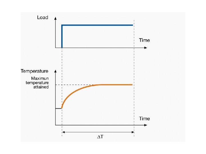
CLASSES OF MOTOR DUTY 1. Continuous Duty (Constant load torque) • The motor is running long enough and the electric motor temperature reaches the steady state value. • Motors are used in paper mill drives, compressors, conveyors, centrifugal pumps and fans
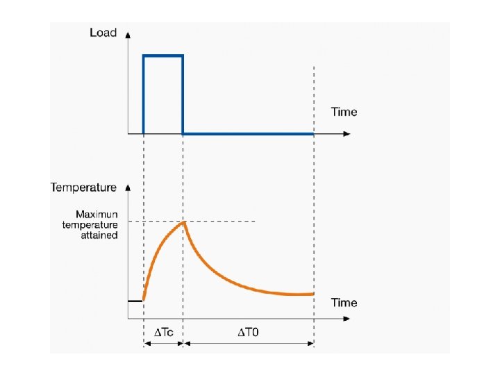
2. Short Time Duty: • In these motors, the time of operation is very low and the heating time is much lower than the cooling time. • The motor cools off to ambient temperature before operating again. These motors are used in crane drives, drives for house hold appliances, valve drives etc.
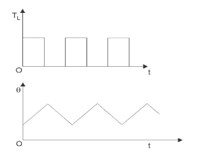
3. Intermittent Periodic Duty • Here the motor operates for some time and then there is rest period. • In both cases, the time is insufficient to raise the temperature to steady state value or cool it off to ambient temperature. • In this duty, heating of machine during starting and braking operations are negligible • pressing, cutting and drilling machine drives.
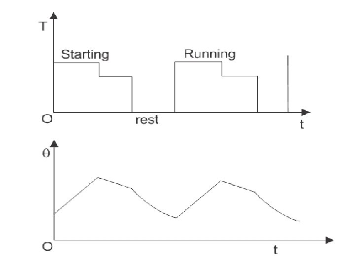
4. Intermittent Period Duty with Starting • In this type of duty, there is a period of starting, which cannot be ignored and there is a heat loss at that time. • After that there is running period and rest period which are not adequate to attain the steady state temperatures. • This motor duty class is widely used in metal cutting and drilling tool drives, mine hoist etc
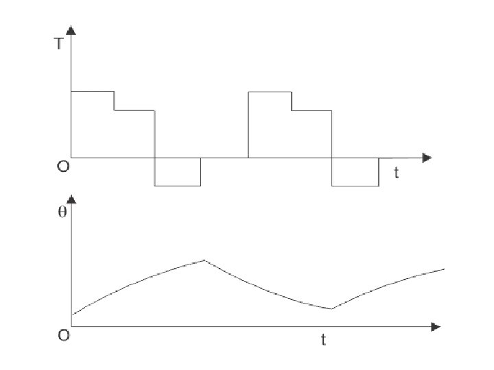
5. Intermittent Periodic Duty with Starting and Braking • In this type of drives, heat loss during starting and braking cannot be ignored. • The corresponding periods are starting period, operating period, braking period and resting period are being too short to reach their steady state temperature value. • This type of duty can be accomplished by single phase/ three phase induction motors and DC shunt motors, DC series motors, DC compound motors, universal motors.
6. Continuous Duty with Intermittent Periodic Loading • In this type of motor duty, everything is same as the periodic duty but here a no load running period occurs instead of the rest period. • Pressing, cutting are the examples of this system.
7. Continuous Duty with Starting and Braking: It is also a period of starting, running and braking and there is no resting period. The main drive of a blooming mill is an example. 8. Continuous Duty with Periodic Speed Changes: In this type of motor duty, there are different running periods at different loads and speeds. But there is no rest period and all the periods are too short to attain the steady state temperatures. Ex: Variable speed drives
7. Continuous Duty with Starting and Braking: It is also a period of starting, running and braking and there is no resting period. The main drive of a blooming mill is an example. 8. Continuous Duty with Periodic Speed Changes: In this type of motor duty, there are different running periods at different loads and speeds. But there is no rest period and all the periods are too short to attain the steady state temperatures. Ex: Variable speed drives