Design Issues for a Muon to Electron Conversion


 reaction:")


/ R e(Z=13) For various")


)bound ->")
 (")

- (Regular muon")


 vs. s along beam 5 3 1")


 Events")


 B( + >e+ ) ~ R e")

 • Participation is open, none of the tasks have been parceled out.")
 Free muon decay, Ee(max)=52. 8")
)bound")

- Slides: 36
Design Issues for a Muon to Electron Conversion Experiment A Description of the MECO Approach James Miller, Boston University FNAL, Sept 15, 2006
Outline • Description of the - > e- process • Current and proposed - > e- limits • General design issues • Description of the MECO Experiment (See detailed talks by W. Molzon and P. Souder tomorrow) • Brief mention of PRISM/PRIME Experiment (see talk by Y. Kuno tomorrow)
Muon to electron conversion • Measure rate of the lepton flavor violating (LFV) reaction: neutrinoless muon to electron conversion in the field of a nucleus, relative to the ordinary muon capture rate on a nucleus. • MECO Goal: R e< 10 -16 which is ~ 6000 x better than the current limit from SINDRUM II: R e<6. 1 x 10 -13 R e is the ratio of rates measured in a muonic atom, R e={Rate( -+A(N, Z) > e-+A(N, Z)} / {Rate( -+A(N, Z) > n +A’(N+1, Z-1)} L =+1, Le=0 > L =0, Le=+1 • In SM, suppressed far below experimental accessibility. • Experimentally accessible rates are commonly predicted in new physics models > excellent process to search for new physics.
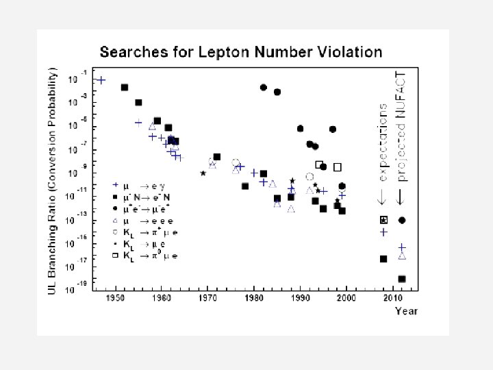
History of Lepton Flavor Violation Searches 1 - N e - N 10 -2 + e+ + e + e+ e- 10 -4 10 -6 10 -8 10 -10 10 -12 K 0 +e. K+ + +e- 10 -14 SINDRUMI I MECO Goal 10 -16 1940 MEG Goal 1950 1960 1970 1980 1990 2000 2010
Muonic Atom Formation and Nuclear Capture A rapid process: low energy - (KE< 30 Me. V) stop in target A(N, Z), undergo atomic cascade arriving primarily in atomic 1 s state • Bohr radii a n 2/(m Z) , BE a m Z 2/n 2 : 200 x smaller radius and 200 x more binding energy than atomic electron > 1 s muon is well inside electron orbits > muon forms hydrogen-like atom • Hydrogenic Radial wavefunction: Rnl(r) a rl Z 3/2 for small r. Prob. of overlap between nucleus and muon wavefunction is proportional to r 2 l. Z 3 which for small r is large only when l=0. • Ordinary Muon Capture Rate - + A(N, Z) > n + A’(N’, Z’) + a + bn + cp: <a>~2, <b>~2, <c>~0. 1 Fundamental process: + p -> n + n Proportional to: (# protons)x(nuclear overlap) ~ Z 4. Capture ~ decay rate for Z=12 • Muon Conversion Rate - + A(N, Z) > A(N, Z) + e Coherent process > proportional to (# nucleons)2 x(nuclear overlap) ~Z 5 > R e a Z > high Z preferred. But… • Nucleus
->e Conversion Rates vs. Z Plot of R e(Z)/ R e(Z=13) For various photon couplings (Rates Normalized to Z=13, Aluminum) Kitano, et al. , PRD 66, 096002 (2002) Aluminum chosen for MECO Nucleus R e(Z) / R e(Al) Bound lifetime Atomic Bind. Energy(1 s) Conversion Energy Prob decay >700 ns Al(13, 27) 1. 0 . 88 s 0. 47 Me. V 104. 97 Me. V 0. 45 Ti(22, ~48) 1. 7 . 328 s 1. 36 Me. V 104. 18 Me. V 0. 16 Au(79, ~197) ~0. 8 -1. 5 . 0726 s 10. 08 Me. V 95. 56 Me. V negligible
SINDRUM II N e N Limit Experience of SINDRUM II carried over to the design of the MECO beam and experimental apparatus SINDRUM II has the Prompt Cosmic Ray best limit on this process Background R e<6. 1 x 10 -13 (in Ti) Expected Signal Muon Decay in Orbit Experimental signature is 105 Me. V e originating in a thin Ti stopping target
Classes of background 1. Prompt: due to beam particles which interact almost immediately when they enter the detector region, producing electrons in the signal region, 100 Me. V<E<106 Me. V, or low energy background. Examples: – – 2. Delayed: due to beam particles which take > few hundred nanoseconds before they produce signals in the detectors. • Examples: – – – 3. Pions: Radiative pion capture, -+A(N, Z) > +X. Very high suppression of pions is required. Major limitation in SINDRUM II. Beam electrons: incident on the target and scattering into the detector region. Need to suppress e with E>100 Me. V In-flight muon decays. Keep p <75 Me. V/c to keep Ee<100 Me. V Antiproton annihilations along beam line or near target- (none in SINDRUM II, potential problem for MECO) Electrons from muon decay in orbit (DIO) Protons, neutrons, gammas from muon capture Photons from radiative muon capture Cosmic Rays- Back/Signal proportional to (run time)/(beam intensity)
Decay of a Muon Bound in Atomic Orbit ( - + N(A, Z))bound -> N(A, Z) + e + n • Decay of a muon bound in an atom is slightly different from ordinary free muon decay… • With nucleus to absorb momentum, neutrinos can carry zero momentum, with electron recoiling off of the nucleus > electron can take almost all of the muon rest energy, and the endpoint energy is the same as a potential conversion electron, but fortunately the probability is very low. (DIO) Free muon decay, endpoint =52. 8 Me. V Ee(max)= (m c 2 Nuclear. Recoil. Energy Atomic. Binding. Energy) For Z=13 (Al), Atomic BE=0. 529 Me. V, Recoil energy=0. 208 Me. V > Ee(max)=104. 96 Me. V Muon decay in Al 1 s bound state, endpoint=104. 96 Me. V
Major Potential Background: Decay of a Muon Bound in Atomic Orbit (DIO, Continued) ( + N(A, Z))bound -> N(A, Z) + e + n • Rate near the maximum energy falls very rapidly. Near endpoint: proportional to (Ee(max)-E)5 • Major potential source of background- Discriminate against it with good electron energy resolution, ~1 Me. V FWHM for MECO Endpoint E (Al)=104. 96 Me. V
Simulation of detected spectrum • Assumptions – Re =1 x 10 -16 – Energy resolution 1 Me. V (FWHM) – Signal region 103. 6<E<105. 1 gives 0. 05 DIO per N >e. N 0. 25 0 10 -4 Log scale Linear scale Acceptance and S/B as Ethresh varied 1
Sources of Background, continued • Radiative muon capture in atomic orbit (RMC)- (Regular muon capture + photon): ( - + A(N, Z))bound > nen + A’(N+1, Z-1) + followed by asymmetric photon conversion in matter, A >e+e-A – Lower endpoint energy than DIO and N->e. N – e- Endpoint energy = Endpoint( >e) - (MA’-MA)c 2 For Al, E max = 102. 5 Me. V (Compare 104. 96 Me. V for N >e. N) P(E > 100. 5 Me. V) = 4 x 10 -9 P( > e+e-, Ee>100. 5 Me. V)=2. 5 x 10 -5 • Radiative capture of pions in atomic orbit (RPC), B. R. ~ 1. 2% Examples: ( - + A(N, Z))bound > + A’*(N+1, Z-1) ( - + A(N, Z))bound > + X followed by asymmetric A > e+e A conversion in matter – Maximum energy ~ 139 Me. V, distribution peaks ~ 110 Me. V. – A potentially serious source of e- background in the 100 -106 Me. V region Ø Pions in the beam line must be greatly suppressed
Backgrounds, continued • Antiprotons: annihilation on the target or in the beam line can produce background electrons. The ’s, which come from 0’s, radiative capture, and other mechanisms, can be very energetic. Pair production, A > Ae+e-, can make electrons 100 -106 Me. V near the conversion electron energy. An 8 Ge. V proton beam is above the antiproton production threshold, but the production cross section is low. (SINDRUM II and TRIUMF experiments used 600 Me. V proton beam and had no antiprotons). Ø antiprotons in the beam line must be highly suppressed • In-flight muon decay: Muons with p>75 Me. V/c can decay to an electron with E>100 Me. V, and need to be suppressed. • Electrons: beam electrons with E> 100 Me. V, especially those which scatter from the stopping target, need to be suppressed.
MECO Pulsed Beam • • In SINDRUM II and TRIUMF >e experiments – Continuous beams of muons were used, fluxes up to few x 107 Hz – Prompt backgrounds (mainly pions) were suppressed by A) vetoing detector events in close time coincidence with signals in beam counters, or B) pions were suppressed using degrader and relying on decay of any remaining slow ’s. – Veto method limits the incident muon rate to ~few x 107 Hz. Beam lines at PSI are limited to ~107 Hz. Implies >1010 seconds of beam would be required to reach the MECO goal of R e< 10 -16. The pions remaining after using the veto or degrader method limits ultimate accuracy ~10 -13 10 -14. MECO approach – No incident beam counters or pion absorbers. – Use an intense pulsed muon beam to suppress prompt background • Stop large flux of muons in a target in a very narrow time bunch (< 100 ns). – 1011 Hz muon stopping rate, injection pulse spacing ~1. 35 s , comparable to muon lifetime of ~. 88 s in atomic orbit in Al • Wait 700 ns after injection until prompt background disappears • Activate detector system from ~ 700 ns until next injection bunch • Attenuate incident beam x 109 between injection bunches (extinction) to suppress prompt background during measurement period. – Build a detector system with high acceptance for e originating in the stopping target in energy range 100 -106 Me. V, low acceptance at lower energies where DIO electrons are copious. – Design a beam line which causes minimal electron background between 100 and 106 Me. V for t >700 ns after injection. Minimize number of particles at other energies which would cause high rates in detectors.
MECO Beam and Detector T B (Tesla) vs. s along beam 5 3 1 m 0 10 20 B=2 T 30 13 m x 0. 25 m rad 4 m x 0. 75 m rad B=5 T B=2. 5 T 10 m x 0. 95 m rad B=1 T
Graded Solenoid Field For adiabatic motion in a straight solenoid with a field gradient, pt 12/B 1= pt 22/B 2 or sin 2(q 1)/B 1= sin 2(q 2)/B 2 • • where sin(q) = pt/p, pt = component of p transverse to B field When the muon spirals from a low field region, B 1, to a high field region, B 2 it will be reflected back when sin 2(q 2)=1, or when sin 2(q 1)=B 1/B 2. pt/p decreases as B decreases > particle movement is enhanced in the direction of decreasing gradient. Effect is acceleration of particle in the direction of decreasing field. – Production Solenoid: Following the MELC scheme: apply a graded field at the primary production target to collect and accelerate muons to downstream direction, and reflect a portion of upstream-going muons + pions back to the downstream direction in order to enhance pion/muon collection efficiency: going downstream, B goes from 5 T to 2. 5 T. – Detector Solenoid: Use graded field at muon stopping target to reflect upstream-going electrons produced there to the downstream direction toward the detectors, to increase acceptance. Going downstream, B goes from 2 T to 1 T. – Transfer Solenoid, which connects the Production Solenoid to the muon stopping target and Detector Solenoid has a small continuous decline of B moving downstream. (Exception is in curved parts of solenoids) This prevents local trapping of charged particles, which could lead to delayed beam particles reaching the stopping target in the measurement window > 700 ns after injection.
Charged particle motion in a toroid Drift Property • For a toroid, charged particles spiraling around the B-field lines drift perpendicular to the toroid bend plane. For R= toroid bending radius, s =distance of travel along the particle’s central orbit, ppar=component of p parallel to B, pperp=component of p perpendicular to B, the vertical displacement is: • Unwanted positively charged particles and high-energy negatively charged particles are displaced vertically after passing curved solenoid portions in the Transport Solenoid and are collimated away.
Production Solenoid • 4 m long x 0. 75 radius • 0. 30 radius inside radiation/heat shield is available for particle transport Transport solenoid downstream 12 • 20 x 10 protons/s, bunch spacing 1. 35 s, 0. 5 s beam, 0. 5 s AGS refill • Protons enter at a 100 angle, toward the upstream direction to reduce background particle flux into transport line • Water-cooled platinum or gold target, 0. 4 cm radius x 16 cm long • B-field tapers going downstream from 5 T to 2. 5 T to capture low-E pions and B=2. 5 T muons toward the transport solenoid (and reflect a portion of those headed upstream) upstream B=5 T
Transport Solenoid • Selects in momentum range B=2. 5 T 13 m x 0. 25 m radius <. 08 Ge. V/c • eliminates electrons >100 Me. V • Absorbs +, e+ , p, pbar, pi+ Components include: B=2. 0 T • Vacuum system • Collimators • Thin beryllium Pbar absorbing window • Neutron absorbers • Stopping Target: 17 x. 02 cm Al disks ~8 cm radius, 5 cm spacing
Detector Solenoid • 10 m long x 0. 95 m radius • Detector solenoid is evacuated to avoid: scattering of background and signal particles; capture of muons in residual gas downstream of stopping target • B graded from 2 T to 1 T in first 4 m in target region • Al target is in a graded field in order to reflect portion of upstream-going electrons back toward detector modify the trajectories of beam electrons with E>100 Me. V to have helix radii< 38 cm so that they do not hit the detector • B=1 T, uniform to 0. 2% in tracking region, 1. 0 % in calorimeter region to obtain necessary energy resolution • Thin low-Z shields around the target absorb protons from muon capture • Central region r<38 cm of detectors is free of material. Charged particles from target with pt<55 Me. V/c pass without interacting to downstream beam dump • Specially enclosed beam dump minimizes particle albedo B=1 T B=2 T
Magnetic Spectrometer for Conversion Electron Momentum Measurement Sample event- Electron starts upstream, reflects in field gradient Longitudinal straw option: Straws: 2. 6 m length 5 mm dia. , 25 m wall thickness to minimize multiple scattering – 2800 total tracker will intercept between 2 and 3 helical turns
Cross section of longitudinal tracker Note: <0. 3% of e- from DIO have pt>55 Me. V/c • Geometry: Octagon with eight vanes, each ~30 cm wide x 2. 6 m long • Straws: 2. 9 m length 5 mm dia. , 25 mm wall thickness to minimize multiple scattering – 2800 total pt=105 Me. V/c • Three layers per plane, outer two resistive, inner conducting • Pads: 30 cm 5 mm wide cathode strips affixed to outer straws - 16640 total pads • Position Resolution: 0. 2 mm (r, f) 1. 5 mm (z) per hit is goal • Energy loss and straggling in the target and multiple scattering in the chambers dominate energy resolution of 1 Me. V FWHM target pt=55 Me. V/c pt=91 Me. V/c
Alternative: Transverse Tracker Geometry: 18 Modules of three planes each, 30° rotation between successive planes Straws: 70 – 130 cm length 5 mm diameter, 15 or 25 m thickness 12960 total straws One layer plane, all straws are conducting Baseline: no z-coordinate, charge division was being considered 136 cm Position Resolution: 0. 2 mm (x, y) Readout Channels: 13 k L and T tracker performances are similar in simulations, and more prototype work is needed to decide on the best option.
Calorimeter • Function: provide initial trigger to system (E>75 Me. V gives trigger rate ~1 k. Hz), and secondary position and energy information to clean up tracks • 1024 Pb. WO 4 crystals, 3. 75 x 12 cm 3 arranged in four vanes. Density 8. 3 g/cm 3, Rad. Length 0. 89 cm, R(moliere)=2. 3 cm, decay time 25 ns • Each crystal is equipped with two large area Avalanche Photo. Diodes: gives larger light yield and allows rejection of charged particles traversing photodiode • Both the front end electronics (amplifier/shapers) and the crystals themselves are cooled to -240 C to improve Pb. WO 4 light yield and reduce APD dark current. • Single crystal performance has been demonstrated with cosmic rays: 38 p. e. /Me. V, electronic noise 0. 7 Me. V, for electrons, s~5 -6 Me. V at 100 Me. V, sposition<1. 5 cm
Cosmic Ray Veto and Shielding • Passive shielding: heavy concrete plus 0. 5 m magnet return steel. Latter also shields CRV scintillator from neutrons coming from stop target. • Hermetic active veto: Three overlapping layers of scintillator consisting of 10 cm x 1 cm x 4. 7 m strips • Goal: Inefficiency of active shielding <10 4 • Cost-efficient solution: MINOS approachextruded rather than cast scintillator, read out with 1. 4 mm dia. wavelength-shifting fiber. • Use multi-anode PMT readout
MECO beam rates and sensitivity Probability Rate (proton flux= 2 x 10¹³ Hz) Events (run time= 2 x 10⁷ seconds, total protons=4 x 10²⁰) Prob. Muon stopped in target per proton 0. 0025 0. 5 x 10¹¹ Hz 1 x 10¹⁸ Prob. capture (Al target) 0. 60 3 x 10¹⁰ Hz 6 x 10¹⁷ Fraction of captures in detector time window 0. 45 (> 700 ns ) 1. 4 x 10¹⁰ Hz 3 x 10¹⁷ Track fitting and selection criteria 0. 19 2. 5 x 10⁹ Hz 5 x 10¹⁶ Detected events for R e=10 -16 2. 5 x 10 -7 Hz 5 > single-event sensitivity 2 x 10 -17 Estimated background 0. 45
Backgrounds (Extinction ~ 10 -9, energy resolution 1 Me. V FWHM, 4 x 10²⁰ protons)
PRISM=Phase Rotated Intense Slow Muon source, PRIME=PRISM Mu e, FFAG= Fixed-Field Alternating Gradient synchrotron
Comparison of MECO and PRISM/PRIME MECO PRISM/PRIME R e goal <10 16 <10 18 Proton beam 8 Ge. V, 40 x 1012 Hz, ~1 MHz bunch rate 50 Ge. V(JPARC), 100 x 1012 Hz, ~10 -100 Hz bunch rate (JPARC and FFAG cycle limits) Muon momentum <77 Me. V/c 68 Me. V/c +- 3% > thin target Muon stop rates . 5 x 10¹¹ Hz, 2 year run 1011 to 1012 Hz, 5 year run Extinction <10 9, use internal and external kickers <10 10, FFAG suppresses pions, etc. to high order Target Al or perhaps Ti Ti or higher Z (minimal detector measurement delay) Detector displaced downstream from stopping target in a straight solenoid FWHM<1 Me. V Target and detector separated by momentum-selecting toroid and line-of sight shielding FWHM<0. 3 Me. V
Comparison with + >e+ N >e-N (+) B( + >e+ ) ~ R e for non-photonic processes (+) Far less background at the signal energy than + >e+ and no accidental coincidences • Requires special muon source • MECO: R e<10 -16 • PRISM/PRIME: R e<10 -18 + >e+ (+) B( + >e+ )=200 300 x R e for photonic processes (-) Signal: coincidence of back-to-back e+ and . Large accidental background rate: E(e+) = E( ) ~ 52. 83 Me. V, where there is a huge background of positrons from ordinary muon decay, + >e+n ne, . (+) Low-energy muon flux, + (surface beam) > • Requires state-of-the-art detector • Current limit BR( + >e+ )<1. 2 x 10 12 • MEG (PSI) goal: BR<10 -13. Long-term with upgrade, BR<10 -14 (+) Funded and under construction
Summary • The physics potential of N >e. N is excellent. • The MECO Beam line magnet systems received funding priority, and an advanced design was produced at MIT. • The detector systems are at the detailed conceptual stage- no potential show-stoppers are seen. A very good detector is needed, but no new inventions are required. Some initial prototype work has been done for the trackers, calorimeters and cosmic ray veto counters. • Groups were awaiting funding to build prototypes when the project was cancelled- so there is lots of hands-on development work to do. • A lot of detailed simulation work has been done, but more is needed. For example with the detailed magnet design, we can study the cost drivers in detail and perhaps find some savings, or more studies of backgrounds and shielding, L vs. T trackers, etc. • The MECO concept is a viable candidate experimental arrangement, with many man-years of design effort invested, and with many successful detailed reviews. • There is the possibility that the design could be modified to improve performance and/or to reduce cost.
Summary (Continued) • Participation is open, none of the tasks have been parceled out. • There is plenty of interesting development work to do. • You are invited to join in!
Distribution of electron energies from decay in orbit (DIO) Free muon decay, Ee(max)=52. 8 Me. V Bound muon decay A Aluminum 1 s state l energy=104. 96 u Endpoint Lifetime=0. 88 s m i n DIO contribution to R e negligible, need detector electron energy resolution • To keep <1 Me. V u (FWHM) for 100 -106 Me. V electrons, with minimal high-side tails. • Detector m acceptance needs to be high for 100 -106 Me. V electrons, but to control rates needs to be minimized to avoid copious low energy electrons. • Backgrounds need to be eliminated between 100 -106 Me. V
Major Background: Decay of a Muon Bound in Atomic Orbit ( + N(A, Z))bound > N(A, Z) + e + n (DIO) • With nucleus to absorb momentum, neutrinos can carry zero momentum, with electron recoiling off of the nucleus > endpoint energy same as a potential conversion electron Ee(max)=m c 2 -Recoil-Atomic. BE For Z=13 (Al), Atomic BE=0. 529 Me. V, Recoil energy=0. 208 Me. V > Ee(max)=104. 96 Me. V • Rate near the maximum energy falls very rapidly. Near endpoint: proportional to (Ee(max)-E)5 Most important potential source of background- Discriminate against it by measuring electron energy to better than ~1 Me. V FWHM. • Accept events from 103. 6 -105. 1 Me. V > 0. 05 DIO/( N >e. N) if R e~10 -16 Endpoint E (Al)=104. 96 Me. V
Cosmic Ray Veto and Shield • Passive shielding: heavy concrete plus 0. 5 m magnet return steel • Inefficiency of active + passive shielding <10 4 • Three overlapping layers of scintillator