CSE 298 CSE 300 RESEARCH AND DEVELOPMENT OF
- Slides: 80
CSE 298 CSE 300 RESEARCH AND DEVELOPMENT OF A DISTRIBUTED OBJECT COMPUTING SYSTEM USING THE UNIFIED MODELING LANGUAGE AND EXPLORATION OF UML SUPPORT FOR DOC Research and Work By: Hector N. Echegoyen Oliver Scheck Gowri Shankar Hector. Echegoyen@otis. com oliverscheck@email. com gowri@engr. uconn. edu DOC/UML. 1
CSE 298 CSE 300 Overview of Presentation m m m Objectives of the Project Overview of Distributed Banking Application q Modeling and Development plan employed q Description of the components of the application q Demo Brief Introduction to UML and DOC Description and Evaluation of DOC support provided by a few UML modeling tools. Proposals for enhancements to UML/ROSE based on the experiences gained during the project. Future work and conclusion DOC/UML. 2
CSE 298 CSE 300 Objective m Explore UML Modeling techniques/constructs and identify support to DOC. m Employ ROSE to Model and develop a Distributed Banking Application ( with RMI distribution ) m Identify key distribution issues relating to OOM m Explore a few UML modeling tools to identify DOC support. m Suggest enhancements to UML through the experience gained during the project DOC/UML. 3
CSE 298 CSE 300 PROJECT DEVELOPMENT PLAN m m m Exploration Of UML was Done First Decided To Implement Prototype Of DOC App In JAVA Usage Of ROSE Tool Vital To The Process Followed By Suggestions To UML Enhancements In DOC Research Of What Other Tools Offer To Support DOC Application Development Suggestions To ROSE Tool Enhancements To Support DOC/UML. 4
CSE 298 CSE 300 EXPLORATION OF UML m m UML Books and Internet Links Looked At Every Single Diagram Found Direct UML Support For DOC In Two Diagrams q Interfaces (Class & Component) q Deployment Diagram Sequence Diagrams were Useful To Depict Client Server Transactions DOC/UML. 5
CSE 298 CSE 300 HOW DOES IT ALL WORK? m m m m Book Concepts - “Instant UML, The Unified Modeling Language User’s Guide”- OK. How Would a Real Application Use Them? Drawing From Experience. Worth it? Client-Server Application - Banking Had To Closely Resemble Real World DOC Mechanism Use of a Modeling Tool was Vital to The Process Code Generation and Implementation Draw Conclusions from there and Move on to the Next Phase DOC/UML. 6
CHOICE OF PROGRAMMING LANGUAGE CSE 298 CSE 300 m m JAVA was the language of choice q Ease of use q Prior experience working with JAVA Found JAVA Features And Components To Directly Support DOC q Object Serialization q Remote Method Invocation DOC/UML. 7
CSE 298 CSE 300 CHOICE OF MODELING TOOL m m Decided On Rational Rose 98 q Team had some experience with it q Fairly stable q Recognized and used at companies for real development and code generation not just modeling Had to set up the tool for development in a team environment DOC/UML. 8
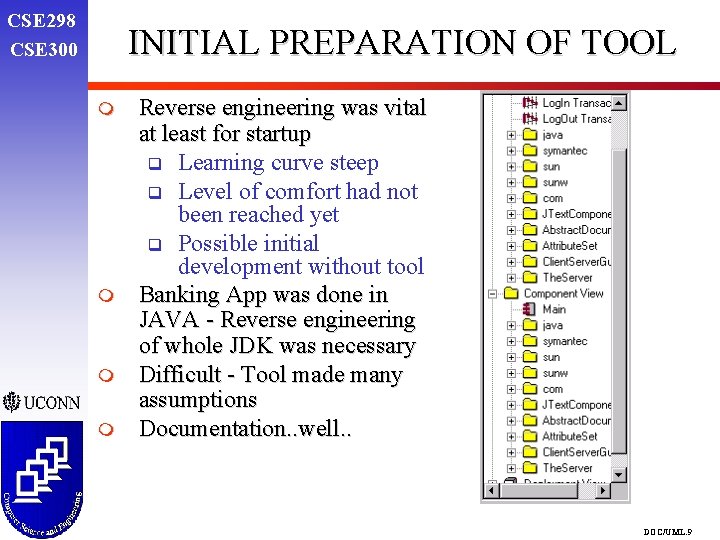
CSE 298 CSE 300 INITIAL PREPARATION OF TOOL m m Reverse engineering was vital at least for startup q Learning curve steep q Level of comfort had not been reached yet q Possible initial development without tool Banking App was done in JAVA - Reverse engineering of whole JDK was necessary Difficult - Tool made many assumptions Documentation. . well. . DOC/UML. 9
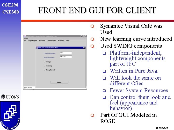
CSE 298 CSE 300 FRONT END GUI FOR CLIENT m m Symantec Visual Café was Used New learning curve introduced Used SWING components q Platform-independent, lightweight components part of JFC q Written in Pure Java. q Will look the same on different OSes q Fewer System Resources q Can control their look and feel (appearance and behavior) Part Of GUI Modeled in ROSE DOC/UML. 10
INITIAL RESEARCH AND DESIGN MEETINGS CSE 298 CSE 300 m m m Agreed to do DOC research concurrently with App design Initial Issues we looked for in our research q Key distribution issues about DOC q What issues were supported by ROSE q Suggestions of enhancements to tools supporting UML q Look for other tools with support for DOC Discussion on definition of Banking System Extent of functionality to be implemented DOC issues to consider during transactions - what makes sense for which scenario. Use Cases? DOC/UML. 11
CSE 298 CSE 300 BEHAVIORAL MODELING SYSTEM USE CASE DOC/UML. 12
SYSTEM USE CASE DESCRIPTION CSE 298 CSE 300 m m m m Hard concept to grasp initially Almost self-explanatory - Focus on functionality of system with interaction of Actors Identified Four major Actors Major functionality and relations to Actors also identified Drew clear definitions of operations for each actor Helped to identify the need for some sort of Role based security (i. e. Customer actor doesn’t perform Audits) Actors directly linked to roles? Wrote Case Scenarios Of Major functions DOC/UML. 13
CSE 298 CSE 300 ARCHITECTURAL MODELING DEPLOYMENT DIAGRAM DOC/UML. 14
DEPLOYMENT DIAGRAM DESCRIPTION CSE 298 CSE 300 m m m To get an idea of how the system would be distributed Concept of more than one type of Bank Server Questions: What kind of functionality is distributed where? Where is security, servers or clients, both? Where should we deploy objects, and which object? Servers handling multiple clients and/or server transactions at the same time How to make our system Generic so that we can run all possible scenarios DOC/UML. 15
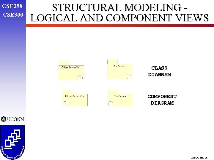
CSE 298 CSE 300 STRUCTURAL MODELING LOGICAL AND COMPONENT VIEWS CLASS DIAGRAM COMPONENT DIAGRAM DOC/UML. 16
CSE 298 CSE 300 INITIAL LOGICAL VIEW OF CLIENT DOC/UML. 17
CSE 298 CSE 300 INIT LOCAL SERVER SIMULATOR AND CLIENT COMP MODEL DOC/UML. 18
CSE 298 CSE 300 INITIAL LOGICAL VIEW OF THE SERVER SIMULATOR DOC/UML. 19
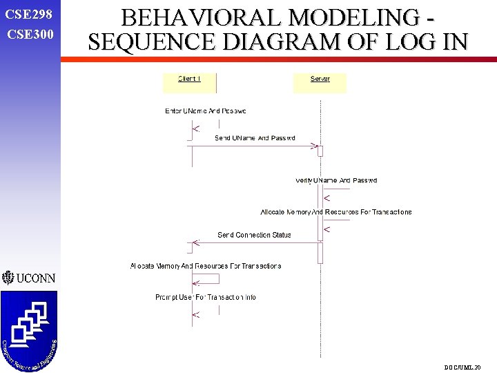
CSE 298 CSE 300 BEHAVIORAL MODELING SEQUENCE DIAGRAM OF LOG IN DOC/UML. 20
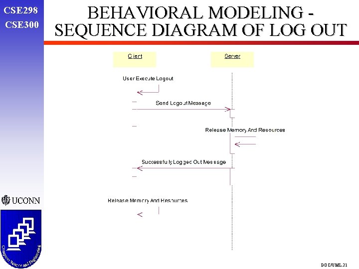
CSE 298 CSE 300 BEHAVIORAL MODELING SEQUENCE DIAGRAM OF LOG OUT DOC/UML. 21
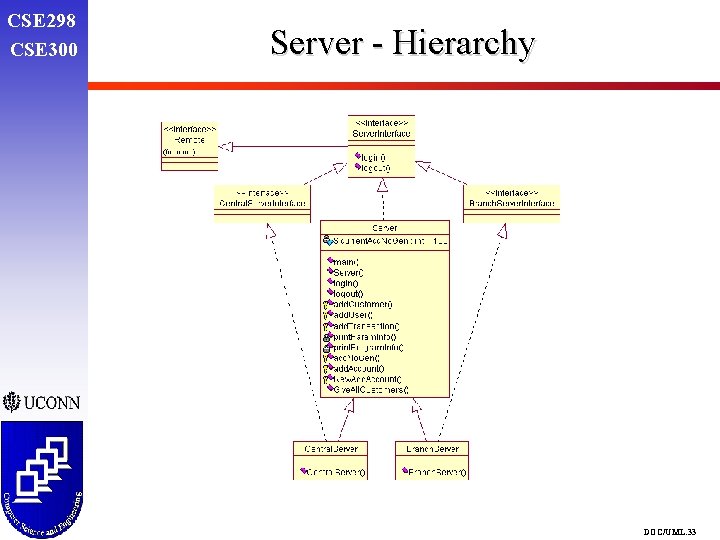
CSE 298 CSE 300 FINAL APPLICATION MODELS AND DEPLOYMENT m m Each of us to explain his/her own piece in detail q Hector - Client GUI and App q Oliver - Main Server Transaction and Interface Hierarchy q Gowri - Main Server Banking Application Only a Prototype - Not a full fledge application. Demo is limited to a couple of transactions. Goal is to prove Java RMI Concepts, Interfaces, UML support of them and know how they work in a Real World App After this phase, ready to jump to the Analysis phase DOC/UML. 22
CSE 298 CSE 300 FINAL DEVELOPMENT - APPLET AND CONNECTION DOC/UML. 23
CSE 298 CSE 300 FINAL DEVELOPMENT - MAIN CLIENT APPLICATION DOC/UML. 24
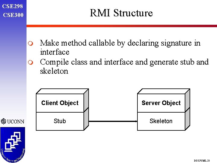
CSE 298 CSE 300 RMI Structure m m Make method callable by declaring signature in interface Compile class and interface and generate stub and skeleton Client Object Server Object Stub Skeleton DOC/UML. 25
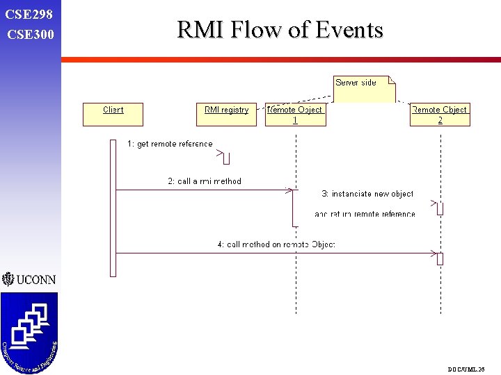
CSE 298 CSE 300 RMI Flow of Events DOC/UML. 26
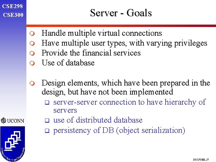
CSE 298 CSE 300 Server - Goals m m m Handle multiple virtual connections Have multiple user types, with varying privileges Provide the financial services Use of database Design elements, which have been prepared in the design, but have not been implemented q server-server connection to have hierarchy of servers q use of distributed database q persistency of DB (object serialization) DOC/UML. 27
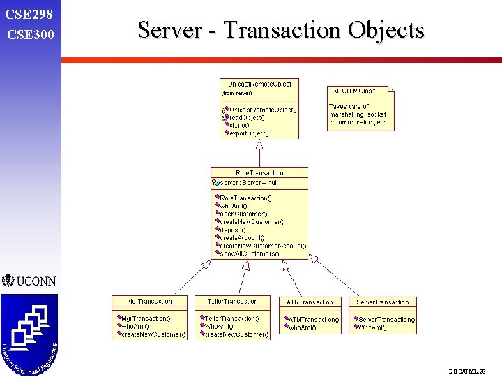
CSE 298 CSE 300 Server - Transaction Objects DOC/UML. 28
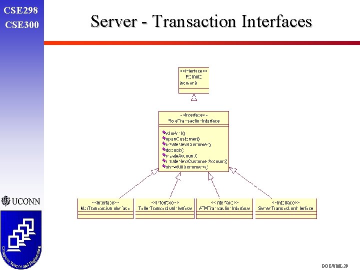
CSE 298 CSE 300 Server - Transaction Interfaces DOC/UML. 29
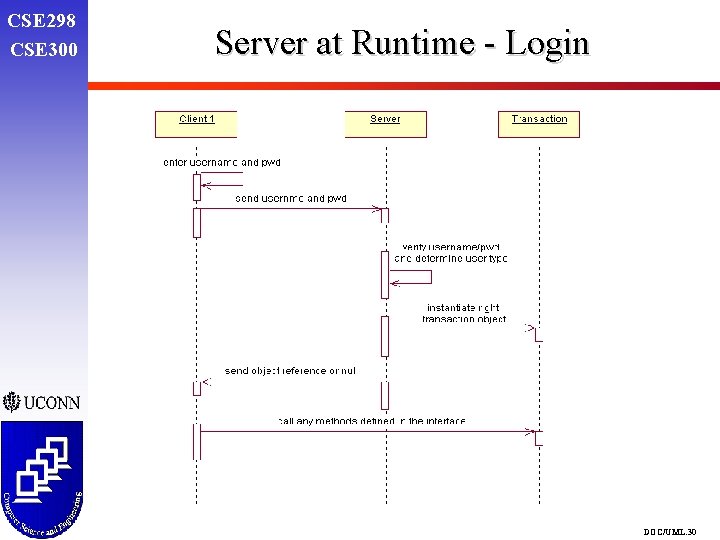
CSE 298 CSE 300 Server at Runtime - Login DOC/UML. 30
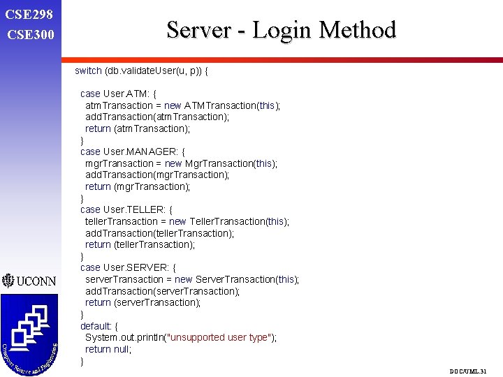
CSE 298 CSE 300 Server - Login Method switch (db. validate. User(u, p)) { case User. ATM: { atm. Transaction = new ATMTransaction(this); add. Transaction(atm. Transaction); return (atm. Transaction); } case User. MANAGER: { mgr. Transaction = new Mgr. Transaction(this); add. Transaction(mgr. Transaction); return (mgr. Transaction); } case User. TELLER: { teller. Transaction = new Teller. Transaction(this); add. Transaction(teller. Transaction); return (teller. Transaction); } case User. SERVER: { server. Transaction = new Server. Transaction(this); add. Transaction(server. Transaction); return (server. Transaction); } default: { System. out. println("unsupported user type"); return null; } DOC/UML. 31
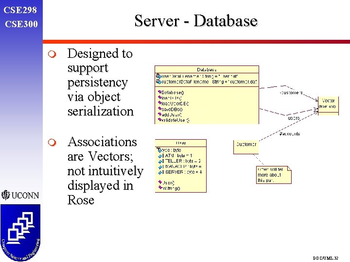
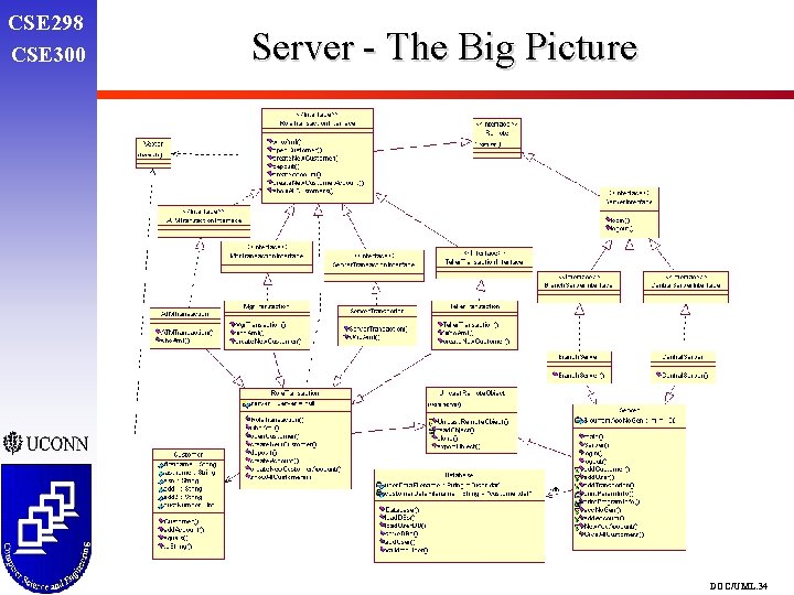
CSE 298 CSE 300 Server - Database m Designed to support persistency via object serialization m Associations are Vectors; not intuitively displayed in Rose DOC/UML. 32
CSE 298 CSE 300 Server - Hierarchy DOC/UML. 33
CSE 298 CSE 300 Server - The Big Picture DOC/UML. 34
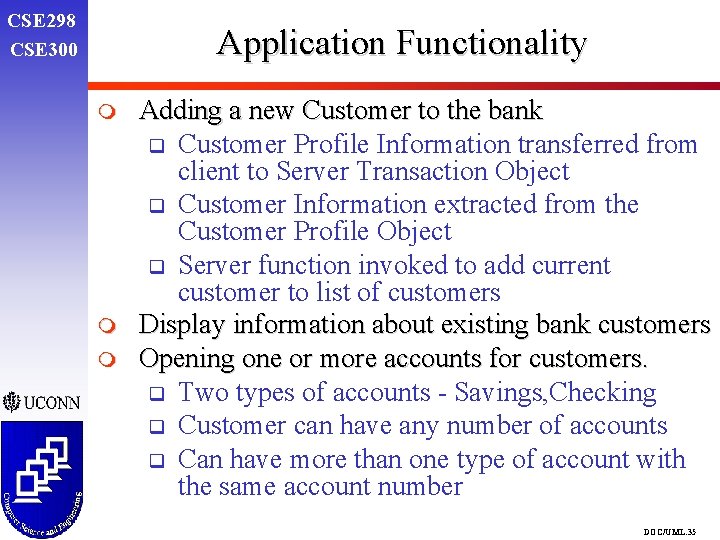
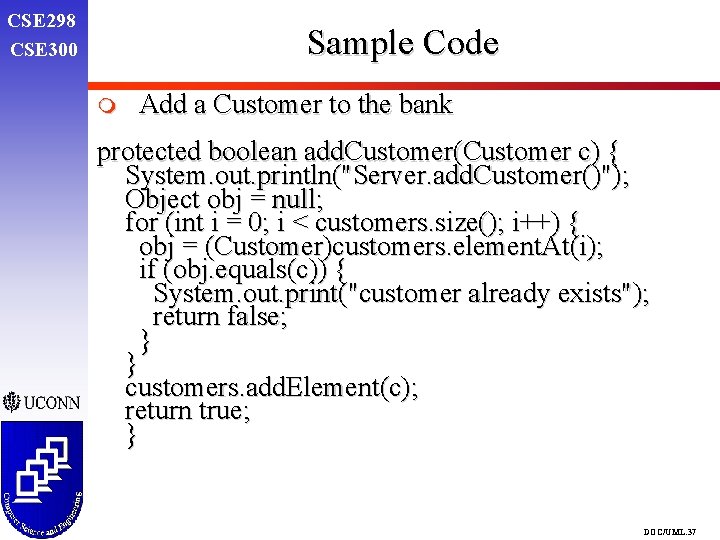
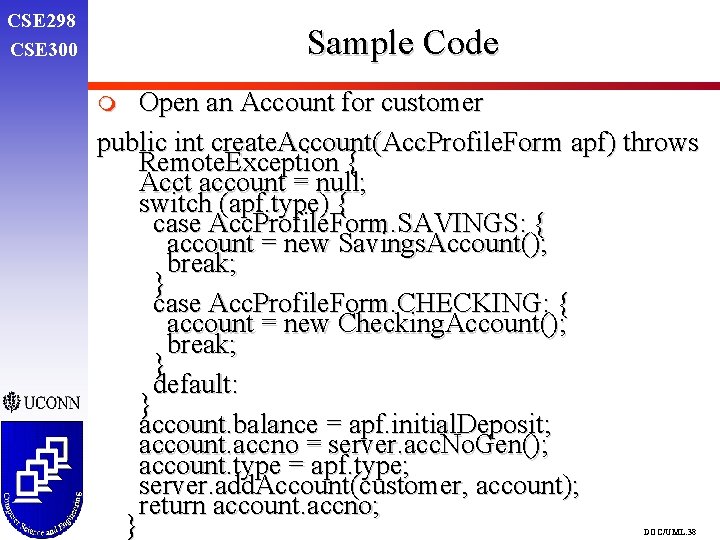
CSE 298 CSE 300 Application Functionality m m m Adding a new Customer to the bank q Customer Profile Information transferred from client to Server Transaction Object q Customer Information extracted from the Customer Profile Object q Server function invoked to add current customer to list of customers Display information about existing bank customers Opening one or more accounts for customers. q Two types of accounts - Savings, Checking q Customer can have any number of accounts q Can have more than one type of account with the same account number DOC/UML. 35
CSE 298 CSE 300 SERVER APPLICATION HIERARCHY DOC/UML. 36
CSE 298 CSE 300 Sample Code m Add a Customer to the bank protected boolean add. Customer(Customer c) { System. out. println("Server. add. Customer()"); Object obj = null; for (int i = 0; i < customers. size(); i++) { obj = (Customer)customers. element. At(i); if (obj. equals(c)) { System. out. print("customer already exists"); return false; } } customers. add. Element(c); return true; } DOC/UML. 37
CSE 298 CSE 300 Sample Code Open an Account for customer public int create. Account(Acc. Profile. Form apf) throws Remote. Exception { Acct account = null; switch (apf. type) { case Acc. Profile. Form. SAVINGS: { account = new Savings. Account(); break; } case Acc. Profile. Form. CHECKING: { account = new Checking. Account(); break; } default: } account. balance = apf. initial. Deposit; account. accno = server. acc. No. Gen(); account. type = apf. type; server. add. Account(customer, account); return account. accno; } m DOC/UML. 38
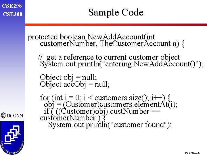
CSE 298 CSE 300 Sample Code protected boolean New. Add. Account(int customer. Number, The. Customer. Account a) { // get a reference to current customer object System. out. println("entering New. Add. Account()"); Object obj = null; Object acc. Obj = null; for (int i = 0; i < customers. size(); i++) { obj = (Customer)customers. element. At(i); if ( ((Customer)obj). cust. Number == customer. Number ) { System. out. println("customer found"); DOC/UML. 39
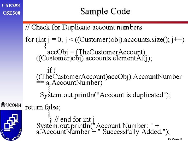
CSE 298 CSE 300 Sample Code // Check for Duplicate account numbers for (int j = 0; j < ((Customer)obj). accounts. size(); j++) { acc. Obj = (The. Customer. Account) ((Customer)obj). accounts. element. At(j); if ( ((The. Customer. Account)acc. Obj). Account. Number == a. Account. Number) { System. out. println("Account is duplicated"); return false; } } // end for int j System. out. println("Account Number: " + a. Account. Number + " Successfully Added. "); DOC/UML. 40
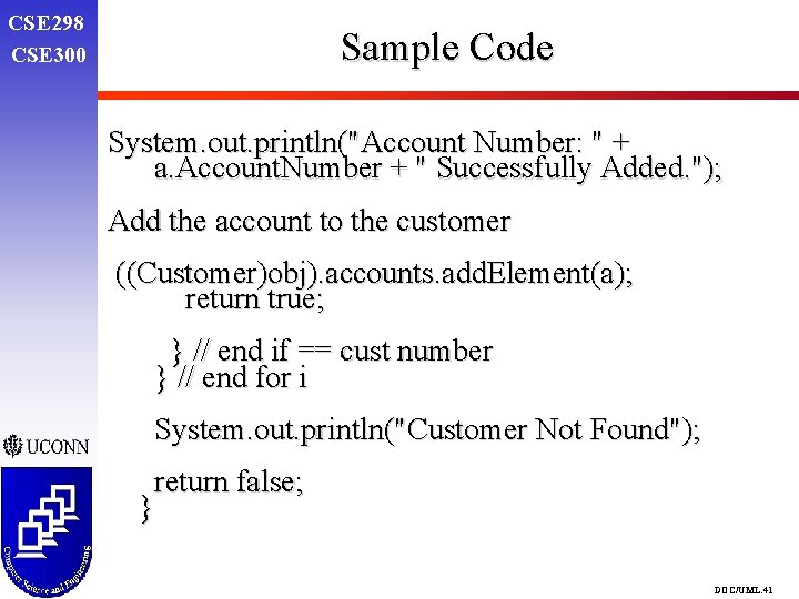
CSE 298 CSE 300 Sample Code System. out. println("Account Number: " + a. Account. Number + " Successfully Added. "); Add the account to the customer ((Customer)obj). accounts. add. Element(a); return true; } // end if == cust number } // end for i System. out. println("Customer Not Found"); return false; } DOC/UML. 41
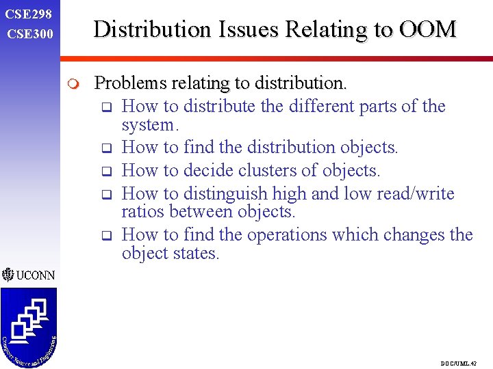
CSE 298 CSE 300 Distribution Issues Relating to OOM m Problems relating to distribution. q How to distribute the different parts of the system. q How to find the distribution objects. q How to decide clusters of objects. q How to distinguish high and low read/write ratios between objects. q How to find the operations which changes the object states. DOC/UML. 42
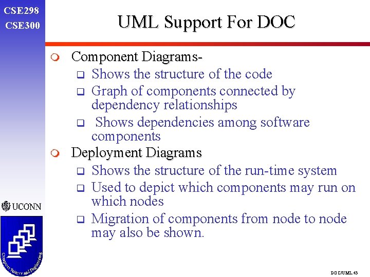
CSE 298 CSE 300 UML Support For DOC m m Component Diagramsq Shows the structure of the code q Graph of components connected by dependency relationships q Shows dependencies among software components Deployment Diagrams q Shows the structure of the run-time system q Used to depict which components may run on which nodes q Migration of components from node to node may also be shown. DOC/UML. 43
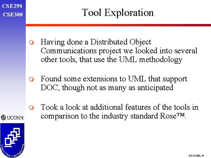
CSE 298 CSE 300 Tool Exploration m Having done a Distributed Object Communications project we looked into several other tools, that use the UML methodology m Found some extensions to UML that support DOC, though not as many as anticipated m Took a look at additional features of the tools in comparison to the industry standard Rose™. DOC/UML. 44
CSE 298 CSE 300 Softmodeler - A Next Generation UML Modeling Tool m Exploration of the capabilities of Softmodeler m Identify support to DOC m Suggest enhancements to UML/Rose through the exploration of Softmodeler. DOC/UML. 45
CSE 298 CSE 300 Capabilites of Softmodeler m m m Supports three important technological trends q Software Components q Distributed Computing q OO Technology Supports the basic UML Constructs q Use Case Diagrams q Object Diagrams q Class Diagrams q Sequence Diagrams No support for q State Diagrams q Activity Diagrams DOC/UML. 46
CSE 298 CSE 300 Features Supporting DOC m True Component Design m Distribution Modeling with support for RMI and CORBA Distribution m Code Generation of Enterprise Java Beans and Java Beans. m Simulation of models during the analysis and design stages. DOC/UML. 47
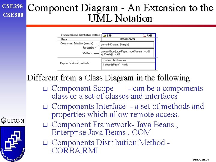
CSE 298 CSE 300 Component Design and Distribution m Provides special notation for defining components m supports component distribution modeling m Allows reuse of existing models of components m Automatic generation of Enterprise Java Beans and Java Beans code m Creation of visual graphical component models from existing EJB and JB source code. m Produces required distribution code (CORBA, Java RMI) DOC/UML. 48
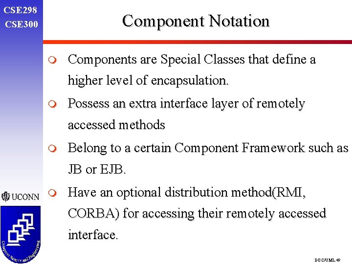
CSE 298 CSE 300 Component Notation m Components are Special Classes that define a higher level of encapsulation. m Possess an extra interface layer of remotely accessed methods m Belong to a certain Component Framework such as JB or EJB. m Have an optional distribution method(RMI, CORBA) for accessing their remotely accessed interface. DOC/UML. 49
CSE 298 CSE 300 Component Diagram - An Extension to the UML Notation Different from a Class Diagram in the following q Component Scope - can be a components class or a set of classes and interfaces q Components Interface - a set of methods and properties which allow remote access. q Component Framework- Java Beans , Enterprise Java Beans , COM q Components Distribution Method CORBA, RMI DOC/UML. 50
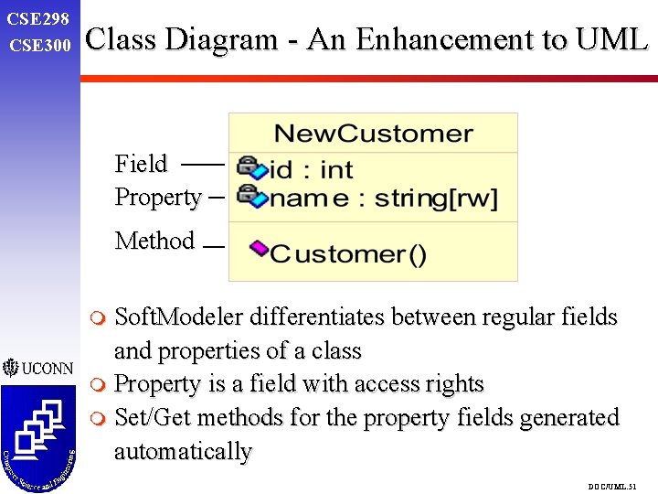
CSE 298 CSE 300 Class Diagram - An Enhancement to UML Field Property Method m Soft. Modeler differentiates between regular fields and properties of a class m Property is a field with access rights m Set/Get methods for the property fields generated automatically DOC/UML. 51
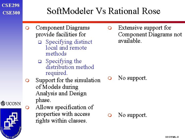
CSE 298 CSE 300 Soft. Modeler Vs Rational Rose m m m Component Diagrams provide facilities for q Specifying distinct local and remote methods q Specifying the distribution method required. Support for the simulation of Models during Analysis and Design phase. Allows specification of properties with access rights within classes. m Extensive support for Component Diagrams not available. m No support. DOC/UML. 52
CSE 298 CSE 300 Soft. Modeler Vs Rational Rose ( Contd. ) m Doest not support state diagrams and Activity Diagrams. m Supports all constructs defined in the UML Notation. DOC/UML. 53
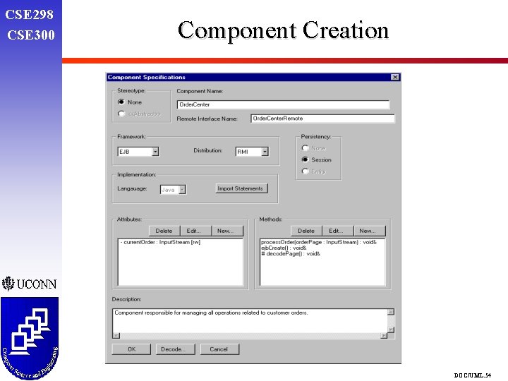
CSE 298 CSE 300 Component Creation DOC/UML. 54
CSE 298 CSE 300 Objec. Time Developer™ m m m Product of Objec. Time Limited http: //www. objectime. com/ Versions for C, C++ Consider themselves as the leading provider of software engineering tools and middleware for developers of distributed systems This product has been incorporated in Rational Rose® Real. Time Uses extensions on UML to incorporate real-time aspects, methodology call ROOM (part of UMLRT) DOC/UML. 55
CSE 298 CSE 300 Objec. Time Developer™ - Features m m m Different levels of views for developers and customers Executable modeling capability for understanding complex, real-time systems designs q tracing messages visually and debugging using graphics q build model from design, load it to target platform, control and animate them from the development platform generates entire applications, not only headers and skeletons, by using formal methods that allow automatisation DOC/UML. 56
CSE 298 CSE 300 Objec. Time Developer™ - Features m Integrates smoothly with other developement tools and operating systems (esp. real-time operating systems m Stated on their web page: ROOM forms the basis for UML-RT, a set of realtime extensions to UML, which is soon to be an OMG standard for general purpose software development. DOC/UML. 57
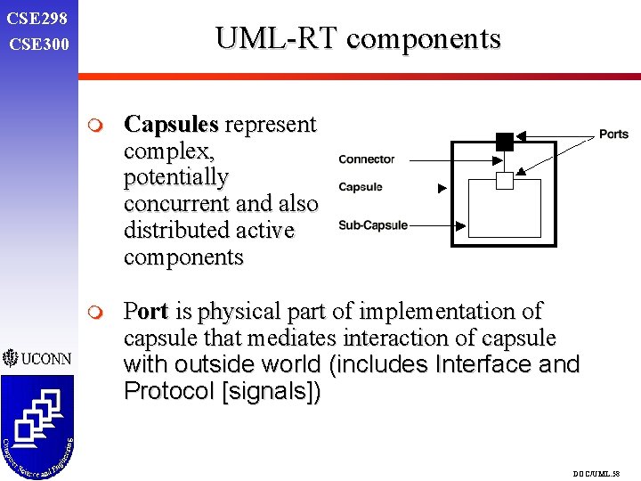
CSE 298 CSE 300 UML-RT components m Capsules represent complex, potentially concurrent and also distributed active components m Port is physical part of implementation of capsule that mediates interaction of capsule with outside world (includes Interface and Protocol [signals]) DOC/UML. 58
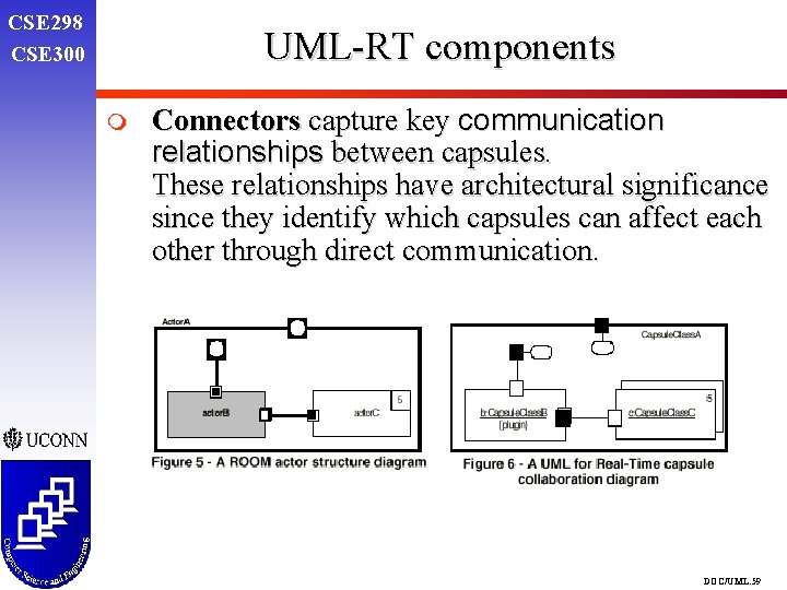
CSE 298 CSE 300 UML-RT components m Connectors capture key communication relationships between capsules. These relationships have architectural significance since they identify which capsules can affect each other through direct communication. DOC/UML. 59
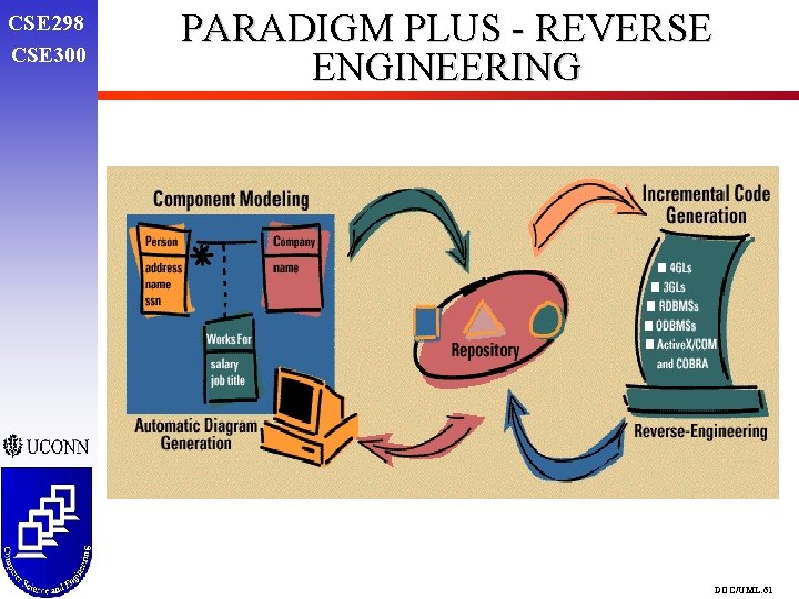
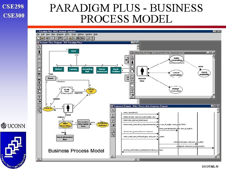
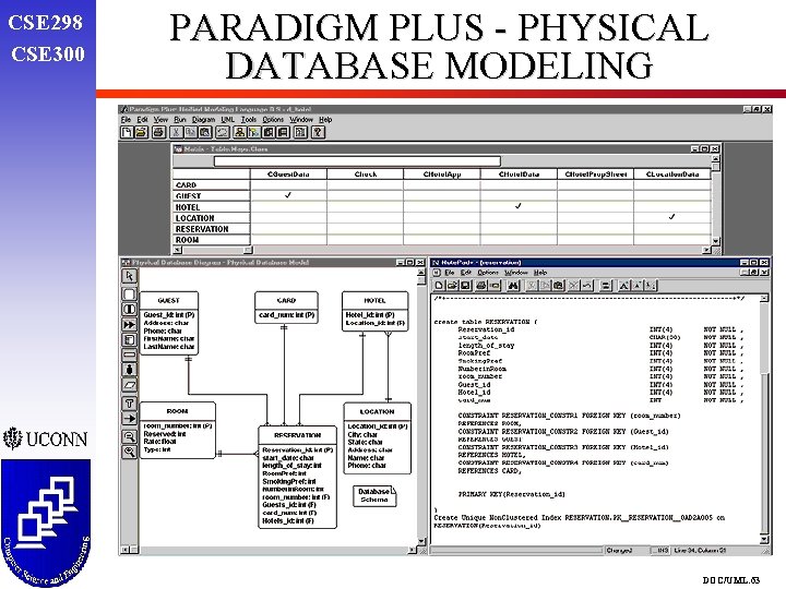
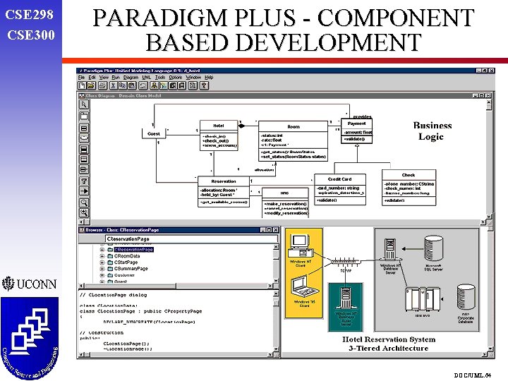
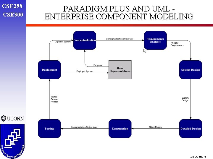
RESEARCH OF UML TOOLS PARADIGM PLUS CSE 298 CSE 300 m m m Enterprise Component Modeling (ECM: share and reuse of components across projects) Models Business Processes Object Repository for component sharing and reuse and to reverse engineer legacy software Fully integrated business process modeling, object modeling, and physical database modeling OOCL (Object Oriented Change and Learning). Business managers capture, model, and communicate corporate strategies to development teams by mapping business requirements directly into use-case, object, and physical database models. DOC/UML. 60
CSE 298 CSE 300 PARADIGM PLUS - REVERSE ENGINEERING DOC/UML. 61
CSE 298 CSE 300 PARADIGM PLUS - BUSINESS PROCESS MODEL DOC/UML. 62
CSE 298 CSE 300 PARADIGM PLUS - PHYSICAL DATABASE MODELING DOC/UML. 63
CSE 298 CSE 300 PARADIGM PLUS - COMPONENT BASED DEVELOPMENT DOC/UML. 64
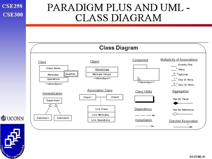
CSE 298 CSE 300 PARADIGM PLUS AND UML CLASS DIAGRAM DOC/UML. 65
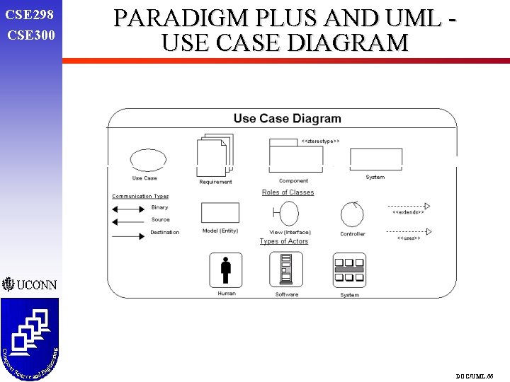
CSE 298 CSE 300 PARADIGM PLUS AND UML USE CASE DIAGRAM DOC/UML. 66
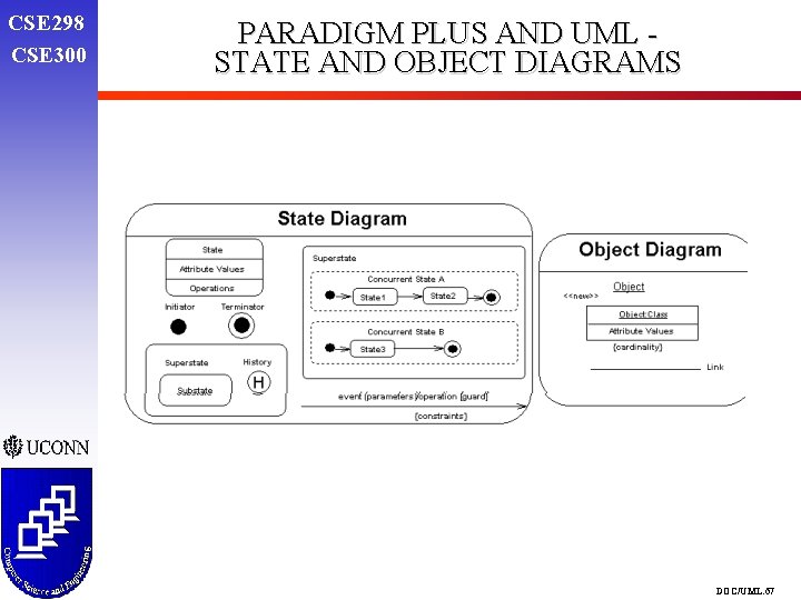
CSE 298 CSE 300 PARADIGM PLUS AND UML STATE AND OBJECT DIAGRAMS DOC/UML. 67
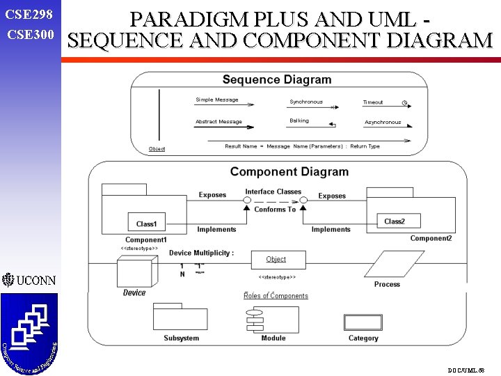
CSE 298 CSE 300 PARADIGM PLUS AND UML SEQUENCE AND COMPONENT DIAGRAM DOC/UML. 68
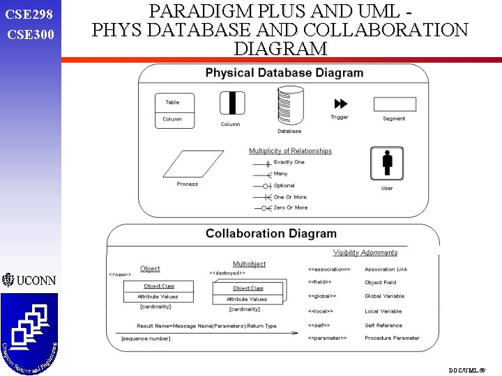
CSE 298 CSE 300 PARADIGM PLUS AND UML PHYS DATABASE AND COLLABORATION DIAGRAM DOC/UML. 69
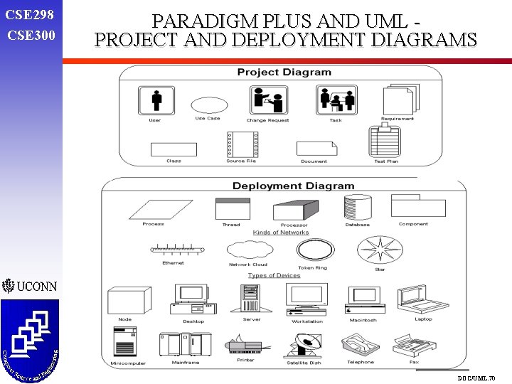
CSE 298 CSE 300 PARADIGM PLUS AND UML PROJECT AND DEPLOYMENT DIAGRAMS DOC/UML. 70
CSE 298 CSE 300 PARADIGM PLUS AND UML ENTERPRISE COMPONENT MODELING DOC/UML. 71
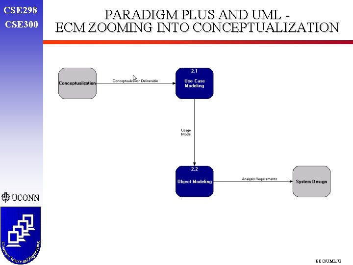
CSE 298 CSE 300 PARADIGM PLUS AND UML ECM ZOOMING INTO CONCEPTUALIZATION DOC/UML. 72
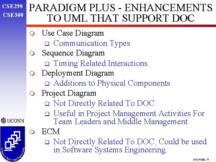
CSE 298 CSE 300 PARADIGM PLUS - ENHANCEMENTS TO UML THAT SUPPORT DOC m m m Use Case Diagram q Communication Types Sequence Diagram q Timing Related Interactions Deployment Diagram q Additions to Physical Components Project Diagram q Not Directly Related To DOC q Useful in Project Management Activities For Team Leaders and Middle Management ECM q Not Directly Related To DOC. Could be used in Software Systems Engineering. DOC/UML. 73
CSE 298 CSE 300 Together® m m Product of Object International, Inc. http: //www. oi. com/ Together/J & Together/C++ President and founder Peter Coad q Coad conducts workshops and performs corporate consultations q publishes books on modeling q provides extensions to UML q tries to propagate his own model called “Coad Object Model” and Archetypes DOC/UML. 74
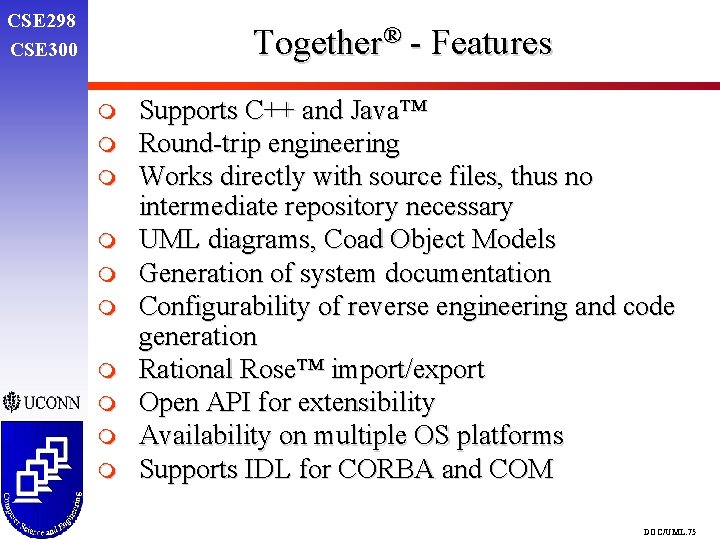
CSE 298 CSE 300 Together® - Features m m m m m Supports C++ and Java™ Round-trip engineering Works directly with source files, thus no intermediate repository necessary UML diagrams, Coad Object Models Generation of system documentation Configurability of reverse engineering and code generation Rational Rose™ import/export Open API for extensibility Availability on multiple OS platforms Supports IDL for CORBA and COM DOC/UML. 75
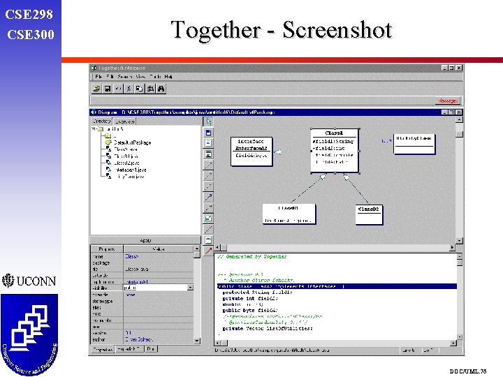
CSE 298 CSE 300 Together - Screenshot DOC/UML. 76
CSE 298 CSE 300 Coad’s Extension to UML m 4 basic “Archetypes” q moment-interval q role q category-entry-like description q party, place or thing m Use of color, because … q psychology behind colors m His Archetypes are actually Patterns DOC/UML. 77
CSE 298 CSE 300 Future Work m m Completion of Application Functionality q Server hierarchy with branch and central server q Distributed DB q Client GUI adapted to new functionality Explore more UML modeling tools to identify further support to DOC/UML. 78
CSE 298 CSE 300 IDENTIFICATION OF ENHANCEMENTS TO UML TO SUPPORT DOC m m Object Deployment q Placing the objects at the right places (C or S) q Ongoing work at UCONN q To be incorporated into the design phase of the model Simulation Capabilities In Deployment Diagrams q Formal Methods, Mathematical Equations, Node Constraints, Connections, Traffic Reports, Line Capacity Maximization, Statistics and Run Time Simulation q Script of Events to generate activity in a DOC System q Lots Of CPU DOC/UML. 79
CSE 298 CSE 300 Conclusions m m Experience gained from the Project q Knowledge about UML notation q Opportunity to model using Rational Rose q Java RMI q More DOC support provided by other tools q Team-work Enhancements to UML that support DOC q Use Case, Deployment and Sequence Diagram additions to UML by Paradigm Plus q Extensions to the Component Diagram, Class Diagram provided by Soft. Modeler q UML-RT as found in Rose for Real-Time DOC/UML. 80