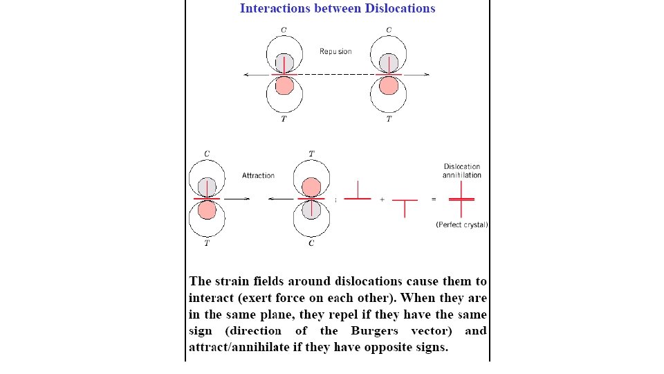
Crystal Imperfection TYPES OF IMPERFECTIONS Vacancy atoms Interstitial


 added to host (A): •")


 change from one")
")
 Perfect crystal. (b) Edge dislocation. (c) Screw dislocation.")

 • Example: add Zn")


- Slides: 35
Crystal Imperfection
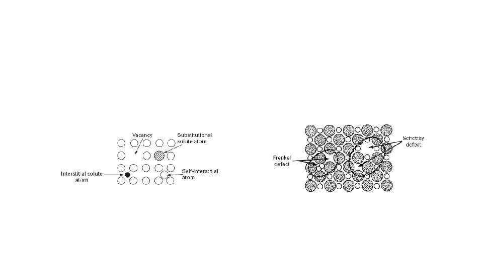
TYPES OF IMPERFECTIONS • Vacancy atoms • Interstitial atoms • Substitutional atoms Point defects • Dislocations Line defects • Grain Boundaries Area defects
Dimensional Range for Different Classes of Defects
EQUIL. CONCENTRATION: POINT DEFECTS • Equilibrium concentration varies with temperature!
MEASURING ACTIVATION ENERGY • • We can get Q from an experiment. • Replot it. . .
ESTIMATING VACANCY CONC. • Find the equil. # of vacancies in 1 m of Cu at 1000 C. • Given:
DEFECTS IN CERAMIC STRUCTURES • Frenkel Defect --a cation is out of place. • Shottky Defect --a paired set of cation and anion vacancies. Adapted from Fig. 13. 20, Callister 5 e. (Fig. 13. 20 is from W. G. Moffatt, G. W. Pearsall, and J. Wulff, The Structure and Properties of Materials, Vol. 1, Structure, John Wiley and Sons, Inc. , p. 78. ) See Fig. 12. 21, Callister 6 e.
POINT DEFECTS IN ALLOYS Two outcomes if impurity (B) added to host (A): • Solid solution of B in A (i. e. , random dist. of point defects) OR Substitutional alloy (e. g. , Cu in Ni) Interstitial alloy (e. g. , C in Fe) • Solid solution of B in A plus particles of a new phase (usually for a larger amount of B) Second phase particle --different composition --often different structure.
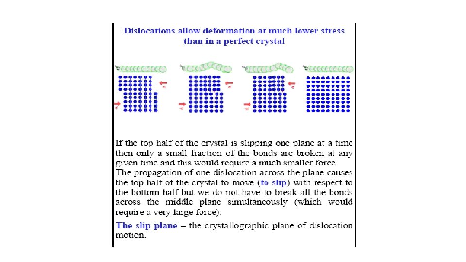
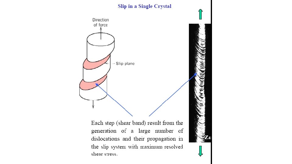
LINE DEFECTS Dislocations: • are line defects, • cause slip between crystal plane when they move, • produce permanent (plastic) deformation. Schematic of a Zinc (HCP): • before deformation • after tensile elongation slip steps
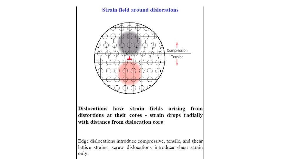
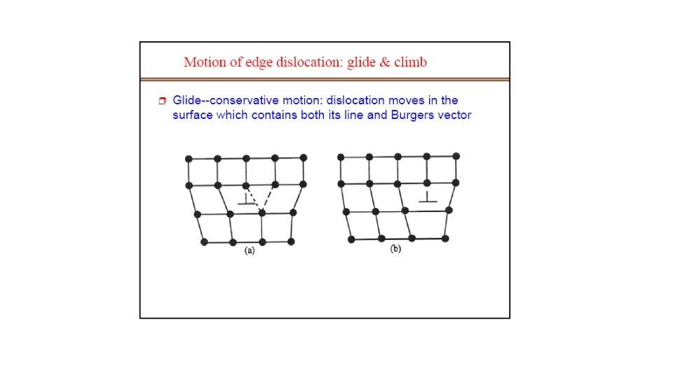
BOND BREAKING AND REMAKING • Dislocation motion requires the successive bumping of a half plane of atoms (from left to right here). • Bonds across the slipping planes are broken and remade in succession. Atomic view of edge dislocation motion from left to right as a crystal is sheared. (Courtesy P. M. Anderson)
DISLOCATIONS & MATERIALS CLASSES • Metals: Disl. motion easier. -non-directional bonding -close-packed directions for slip. electron cloud • Covalent Ceramics (Si, diamond): Motion hard. -directional (angular) bonding • Ionic Ceramics (Na. Cl): Motion hard. -need to avoid ++ and -neighbors. ion cores
DISLOCATION MOTION • Produces plastic deformation, • Depends on incrementally breaking bonds. Plastically stretched zinc single crystal. Adapted from Fig. 7. 9, Callister 6 e. (Fig. 7. 9 is from C. F. Elam, The Distortion of Metal Crystals, Adapted from Fig. 7. 1, Callister 6 e. (Fig. 7. 1 is adapted from A. G. Guy, Essentials of Materials Science, Mc. Graw-Hill Book Company, New York, 1976. p. 153. ) • If dislocations don't move, deformation doesn't happen! Oxford University Press, London, 1935. ) Adapted from Fig. 7. 8, Callister 6 e.
DISLOCATIONS & CRYSTAL STRUCTURE • Structure: close-packed planes & directions are preferred. view onto two close-packed planes. • Comparison among crystal structures: FCC: many close-packed planes/directions; HCP: only one plane, 3 directions; BCC: none • Results of tensile testing. Mg (HCP) tensile direction Al (FCC)
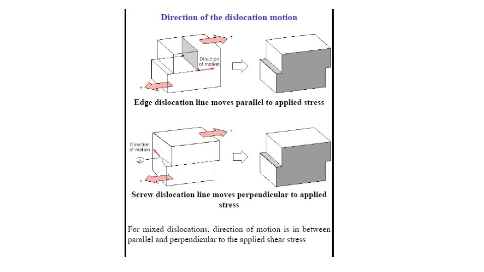
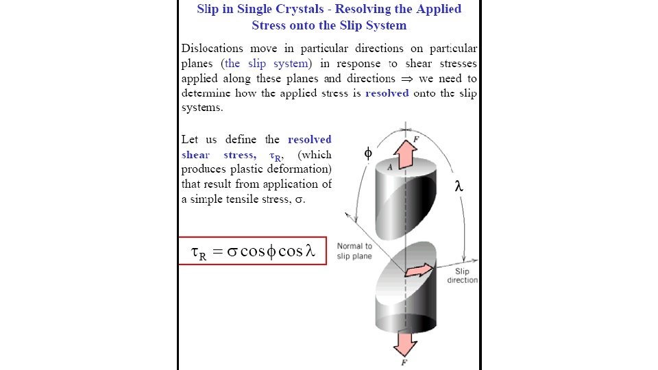
STRESS AND DISLOCATION MOTION • Crystals slip due to a resolved shear stress, t. R. • Applied tension can produce such a stress. slip plane normal, ns n p sli rec di tio n o i p t sli rec di p sli rec di tio n
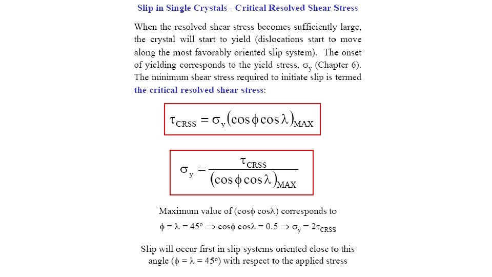
CRITICAL RESOLVED SHEAR STRESS • Condition for dislocation motion: • Crystal orientation can make it easy or hard to move disl.
DISL. MOTION IN POLYCRYSTALS • Slip planes & directions (l, f) change from one crystal to another. Adapted from Fig. 7. 10, Callister 6 e. (Fig. 7. 10 is courtesy of C. Brady, National Bureau of Standards [now the National Institute of Standards and Technology, Gaithersburg, MD]. ) • t. R will vary from one crystal to another. • The crystal with the largest t. R yields first. • Other (less favorably oriented) crystals yield later. 300 mm
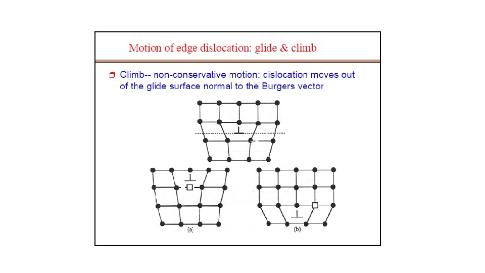
Formation of Point Defects Formation of point defects by the annihilation of dislocations. (a) Row of vacancies. (b) Row of interstitials.
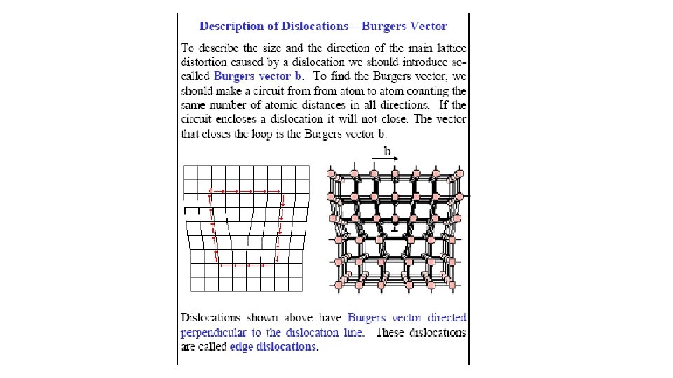
Edge and Screw Dislocations . (a) Perfect crystal. (b) Edge dislocation. (c) Screw dislocation.
Strengthening mechanisms • Pure metals have low resistance to dislocation motion, thus low yield strength. • Increase the resistance by strengthening: • Solution strengthening • Precipitate strengthening • Work hardening
Solution strengthening • Add impurities to form solid solution (alloy) • Example: add Zn in Cu to form brass, strength increased by up to 10 times. Cu Cu Zn Cu Cu Bigger Zn atoms make the slip plane “rougher”, thus increase the resistance to dislocation motion.
Work-hardening • Dislocations interact and obstruct each other. • Accounts for higher strength of cold rolled steels. UTS YU YL × Strain hardening f
AREA DEFECTS: GRAIN BOUNDARIES Grain boundaries: • • are boundaries between crystals. are produced by the solidification process, for example. have a change in crystal orientation across them. impede dislocation motion. Metal Ingot Schematic Adapted from Fig. 4. 7, Callister 6 e. ~ 8 cm Adapted from Fig. 4. 10, Callister 6 e. (Fig. 4. 10 is from Metals Handbook, Vol. 9, 9 th edition, Metallography and Microstructures, Am. Society for Metals, Metals Park, OH, 1985. )
SUMMARY • Point, Line, and Area defects arise in solids. • The number and type of defects can be varied and controlled (e. g. , T controls vacancy conc. ) • Defects affect material properties (e. g. , grain boundaries control crystal slip). • Defects may be desirable or undesirable (e. g. , dislocations may be good or bad, depending on whether plastic deformation is desirable or not. )