COUPLINGS Couplings are mechanical devices which connect one


 coupling with pins.")


- Slides: 56
COUPLINGS Couplings are mechanical devices which connect one shaft to another or to couple a drive shaft to a driven shaft. Shaft coupling are used in machinery for next purposes. 1. To provide for the connection of shafts of units that are manufactured separately, such as a motor and a generator, and to provide for disconnection for repairs or alterations, 2. To provide for misalignment of the shafts or to introduce mechanical flexibility. 3. To reduce the transmission of shock loads from one shaft to another. 4. To introduce protection against overloads. 5. T o alter the vibration characteristics of rotating units.
Objective of this chapter: 1. Describe rigid couplings and flexible couplings. 2. Describe several types of couplings. 3. Describe retaining rings and other means of locating elements on shafts. 4. Specify suitable seals for shafts and other types of machine elements. There are two general types of couplings: rigid and flexible.
Shaft couplings is used under the following conditions. 1. With shafts having collinear axes, that is axes in the same straight line. Rigid flexible couplings are used. 2. With shafts having intersecting axes, in which case a universal coupling is employed. 3. With shafts whose axes are parallel and at a relatively small distance apart. Here the double slider crank principle of mechanism is used.
Rigid Couplings • Coupling has no flexibility or resilience, and used for the shafts that are to be connected to be in good alignment, both laterally and angularity, in order to avoid excessive loads on the coupling, on the shafts, or on the shaft bearings. Alignment of shaft center lines
Some commonly used types of rigid couplings (there is a large variety of rigid couplings in use) Sleeve or Muff coupling Sleeve (Muff) couplings with key
Sleeve (Muff) coupling with pins.
• Sleeve coupling is hollow cylinder which is fitted over the ends of the two shafts to be connected and is then keyed there to by a sunk key. • The three links acting as a single rigid member. • Securing the joint made with the help pressure fits, screws and pins. • The coupling is simple in design and manufacture. • The disadvantages of the sleeve coupling are the difficulty in disassembly that is either the sleeve must be shifted along the shaft at least half its length or the shafts must be drawn apart to free the entire length of the coupling. • The necessity for highly accurate axial of the shafts since misalignment of shaft axes due to negligent assembly, or deformation under load, gives rise to forces that deflect the shafts.
• The material of the sleeve is usually cast iron. • The sleeve and key of this coupling must safely resist the torsional moment, Mt of the shaft. • The effective length of the key to be used in the crosssectional area, should provide the resistance of the key. • Often the coupling key is made in two parts, so one in each shaft. • The taper pin is checked for induced shear stress that less than the allowable shear stress of the pin.
Couplings for small diameter of shafts Small diameters of shafts are usually d ≤ 10 mm. Moment from shaft to shaft transmitted by: 1. The friction force between screw and shaft surfaces 2. Surface geometry of a shaft that play role of the stopper 3. The friction force between shafts and collets Couplings with screw and bolt
Coupling with collets
Clamp Coupling • Clamp coupling is a compression coupling • Coupling is made in two parts, that fit the shaft and are finished off around the periphery and on both ends. Its construction permits of its being readily assembled and removed which distinct advantage. • The two halves of the coupling are clamped tightly against the surface of the shaft ends by through bolts and the torsional moment is transmitted by friction. • In large couplings a key is incorporated between the shafts and coupling transmits the main torsional moment
Clamp or Compression Coupling
The torsional moment is transmitted only through friction between the shafts and coupling halves or through a key • Clamping load on the shaft due to z number of bolts P = (z)(π/4)dc 2*st. where z is the number of effective bolts for each shaft. dc = diameter of the bolt used for clamping. st= allowable tensile stress in the bolt. • Tangential force of shaft will be T = μP = μ*(π/4)(dc 2 *st *z) μ = coefficient of friction between the shaft and sleeve material. An average value of μ = 0. 3.
• The torsioinal moment transmitted by the coupling M = T *d/2 = μ*(π/4)(dc 2 *st *z)(d/2) = μ*(π/8)(dc 2 *st *z)d d = diameter of shaft. • Torsional moment M must be equal to the torsional moment Mt to be transmitted by the coupling M = Mt • Power transmitted by the coupling W = angular velocity if a shaft = Mt (Nm/s)
Flange coupling • A rigid flange coupling consists of two cast iron flanges are mounted and keyed on the ends of each shaft and are drawn together by a series of bolts. • For more accurate connection, on the ends of the flange couplings machined the centering surfaces. • The bolts holding the flanges together are sometimes reduced in diameter so that they would readilybreak or shear off in the event of a damaging overload that to serve as a safety device.
Rigid coupling Cutaway view
• The load path is then from the driving shaft to its flange, through the bolts, into the mating flange, and out to the driven shaft. • The torque places the bolts in shear. • The total shear force on the bolts depends on the radius of the bolt circle, Dbc/2, and the torque, T. That is, F = T/(Dbc/2) = 2 T/Dbc • Letting N be the number of bolts, the shear stress in each bolt is Letting the stress equal the design stress in shear and solving for the bolt diameter,
Flexible Couplings • Flexible couplings are designed to transmit torque smoothly while permitting some axial, radial, and angular misalignment. • The flexibility is such that when misalignment does occur, parts of the coupling move with little or no resistance. Thus, no significant axial or bending stresses are developed in the shaft. • Many types of flexible couplings are available commercially. • The degree of misalignment that can be accommodated by a coupling should be obtained from the catalog data, • Couplings may allow parallel misalignment 0. 127 0. 762 mm or more. • Typical allowable angular misalignment is ± 3°. • Axial movement allowed (end float) is up to 0. 762 mm for many types of couplings.
The flexible couplings have designed by two categories 1. Couplings with incorporated flexible members that anticipates both misalignment and impact. Couplings bring to bear on the shafts and bearings an additional load, which depends on the rigidity of the coupling and relative shift if the connected shafts. 2. Couplings with cinematical flexibility by the use of rigid members in which constraint is absent in certain directions. These couplings re rigid slip couplings and universal joint couplings and should be lubricated. Couplings can be used for any velocities and load and cause comparatively small additional loads on shafts and bearings.
Rigid slip flexible coupling. Pressure distribution on the tongue sides Proportions: d 1 = 2 d, D = (3 – 4)d. h = t/2. t = D/6 or 0. 45 d. w = t/2. t 1 = 0. 75 d, l = 1. 75 d.
• A coupling can be used for shafts which are not in alignment but whose axes are parallel upto the extent of 0. 05 times the shaft diameter. • This type of coupling also minor axial misalignment of shafts can be compensated. • The coupling consists of two flanges keyed or screwed to the shafts and the flanges have the slots on the face surface. A cylindrical piece called disc with a tongues a and b are at right angle to each other running across each flat face. • The tongues a and b fit into the slot of the right and left handed flange and allows for horizontal and vertical relative motion of the parts. The resultant of these two components of motion will accommodate lateral misalignment of the shafts as they rotate.
• The design of the slip coupling is based on the allowable pressure between the faces of the slots and the tongues (from a maximum value p at the periphery of the coupling to zero at the center line). The allowable pressure p must not exceed 8. 5 N/mm 2 for normal misalignment. • Distance to the pressure area centroid from the center line l = (2/3 * 1/2 )D= 1/3 D where D is the diameter of the disc. • Total pressure on each side F = (1/4) p. Dh • where p is the maximum allowable pressure and h is depth of the slot or tongue.
• The torsional moment transmitted Mt = 2 F * l=2* 1/4 p. Dh * 1/3 D= 1/6 p. D 2 h • Then the power, which can be transmitted by this coupling. P = 2πn(rev/min)Mt(Nm)/60 = 2πn/60 *1/ 6 p. D 2 h = πp. D 2 h n/180 (w) n = speed of the shaft.
Pin Type Flexible Coupling The coupling flanges are made from cast iron or steel forgings or steel castings. Pins are made from normalized steel.
• The flexible rubber bushed coupling is the simplest and commonest type of coupling. • Couplings are transmitted motion from one half of flange to the other half by means of pins or bolts. • The pins are rigidly bolted to one flange and loosely fitted in the corresponding holes of the other flange. • A flexible coupling is used, where the driving and driven units are mounted on a common base plate, where excessive misalignment is not likely. • A coupling makes up for the parallel misalignment of shafts upto 0. 5 mm, angular misalignment upto 1. 5 o and axial displacement.
• A coupling can drive in either direction, absorb impulses, shocks and vibrations. Rubber, leather or some other material covers the pins. • The driving pins are easily removable, either shaft may be removed without having to be shifted endwise. • Couplings are made with capacities 12000 k. W at 2500 rev/min. • The coupling halves are mounted with axial clearance. • For this coupling, it is necessary to reduce the bearing pressure on the rubber bushes which are the main feature of design.
• The different stresses acting over the pin will be 1. Bearing Stress on the rubber bushes. The force F applied at each pin to transmit the given torsional moment is, F= Mt/(N*R) where Mt is the torsional moment R is the radius of the pitch circle N is the number of pins used, (obtained by relation N = (d/25) +3 (mm)
• The outer diameter of the rubber bush d 1 = diameter of pin + 2 thickness of brass sleeve +2 thickness of rubber bush. • The rubber bushes are available in thickness of 6 – 9 mm • The thickness of brass sleeve may be taken as 1. 5 mm. • Projected area A = p*d 1*l where l is the length of the bush, p is the bearing pressure A suitable value for p, having regard to the life and durability of the rubber will be 0. 35 N/mm 2 Relation of A projected area can give the length of the blush.
2. Shear Stress • The threaded portion of the pin on which the nut is to be tightened should be as short as possible, so that shear can be taken by the unthreaded neck. • Shear stress due to the transmitted torsional moment Mt on diameter do will be, Ss = F /area of neck= F/(π/4)do 2 • Check that this value is less than the allowable shear stress,
3. Bending Stress • The pin is not rigidly held in the left hand flange, and the rubber is compressible, the force F at the enlarged end will exert a bending action on the pin. • The length under bending of pin will be l and the longitudinal resistance to bending will be neglected. The type of the loading is distributed. Pin
• The clearance between the flanges is usually kept as 5 9 mm. • The load F on the pin is uniformly distributed on the length (1 -c), therefore the arm under bending moment upto the reduced area = (l-c)1/2 + C = l 1 • Maximum bending moment= F*l 1 • Induced bending stress will be Sb = Fl 1/(π/32)d 03 This value should be less than the allowable bending stress.
4. Initial tightening stresses • Care should be taken during assembly that the nuts are not tightened down unnecessarily. • The proportions of the coupling may now be taken as given below, where d is the shaft diameter, and t 1 is the boss thickness, outer diameter of boss = 2 d length of the boss =1. 5 d diameter of pin do= 0. 5 d/z 1/2 thickness of the right hand side flange= 1/2 t 1+6. 5 mm thickness of the left hand side flange = length of bush C width of the flanges = length of bush + 10 mm
Slip Coupling • A slip coupling is permit relative rotation, or slip, between the driving shaft and the driven shaft. • A slip coupling is a safety device that prevents damage to rotating parts because of overloading. • • The slip begins if the load exceeds by 10 20 % the maximum load the shafts and other parts are designed. • • There are many variations in form of this type of coupling.
Slip coupling
The flanged hub a is keyed to the driving member. The driven member b is composed of a flanged hub with friction discs attached to both sides of the flange. • • A number of springs are loaded by screwing down the nuts, and create the pressure on the friction surfaces that ensures a constant maximum moment of friction transmitted by the coupling. • • In case of an overload, (the Mt torsional moment ≥ Mf friction moment) of the coupling, the discs start to slip. • • Further increase of the torsional moment on the shaft is safe guarded against failure.
• Slip in a coupling occurs frequently, and no measurable wear takes place • It is assumed that the unit pressure p between the discs is uniform and that the axial force Fa is exerted by the springs. • The axial force Fa is given by relation Fa=μ/4 (d 22 -d 12)p where μ is the coefficient of friction that can be increased by lining the coupling disc with friction materials. • The tangential force for two pairs of friction surfaces is Ft=2μ/Fa=2μπ/4 (d 22 -d 12)p = μπ/2 (d 22 -d 12)p The mean radius at which the tangential force will be acting as given by relation rm = (d 2+d 1)/(2*2) = (d 2+d 1)/4
• The frictional torsional moment transmitted by the coupling is Mt= Ftrm= μπ p (d 22 -d 12)*(d 2+d 1)/8 • The torsional moment Mt can be equated to the torsional moment to be transmitted by the coupling. • The bearing pressure p should be as low as possible to increase the life of the coupling. The desirable value for the bearing pressure is p = 0. 4 0. 5 N/mm 2 and ≤ 0. 7 N/mm 2. • The ratio of diameter d 2 and d 1 approximately, d 2/d 1 = 1. 6. • The number of springs ranges from 6 to 16 for a shaft diameter of 55 mm to 160 mm. The axial load (tensile load) coming on all the bolts can be calculated from relation axial force Fa.
Universal Flexible Coupling • In cases where the angular or off set misalignment of the shaft reaches values which cannot be accommodated by flexible couplings, the Hooke's coupling or Universal Flexible coupling applied to good advantage. • • The universal coupling is used for two shafts whose center lines form a large angle, as 50 to 150, or even 450. The joint has no torsional flexibility and can accommodate any parallel misalignment, i. e. , shafts must intersect. • Single universal joints have the disadvantage that the rotational speed of the output shaft is non uniform in relation to the input shaft.
• There are many forms of this coupling Hooke's Coupling or Universal Flexible Coupling.
• When applying a universal joint, it is important to take into account the correction factor. This depends on the working angle between the shafts. • • The pin is in double shear. If Mt is the torsional moment to be transmitted and then diameters of the pin dp is calculated by relation. Mt = π/4 dp 2 *Ss *2 d where Ss is the allowable shear stress in the material of pin • The central piece and the fork of the coupling are made from cast iron and the pins are made of steel. A coupling should be lubricated and protected from dust and dirt.
Universal joint components
Automotive universal joint components
Double universal joint
Chain coupling. Torque is transmitted through a double roller chain. Clearances between the chain and the sprocket teeth on the two coupling halves accommodate misalignment. Elastometric member bonded to steel flanges and hubs The features are that it (1) generally minimizes torsional vibration; (2) cushions shock loads; (3) compensates for parallel misalignment up to 0. 031 mm; (4) accommodates angular misalignment of ± 3°; (5) provides adequate end float, ± 0. 031 mm.
Grid-Flex coupling. Torque is transmitted through a flexible spring steel grid. Flexing of the grid permits misalignment and makes it torsionally resilient to resist shock loads. Gear coupling. Torque is transmitted between crown hobbed teeth from the coupling half to the sleeve. The crown shape on the gear teeth permits misalignment.
Bellows coupling. The inherent flexibility of the bellows accommodates the misalignment. PARA-FLEX coupling. Using an elastomeric element permits misalignment and cushions shocks.
Jaw-Type coupling Types of inserts Assembled coupling Neoprene, Bronze, Polyurethane
RETAINING RINGS AND OTHER MEANS OF AXIAL LOCATION Retaining rings hold assemblies together or hold parts on shafts. • The choice of the means for axial location depends heavily on whether or not axial thrust is transmitted by the element. Many of joining need for axial location affects only due to incidental forces, vibration, handling, and shipping. Although not severe, these forces should not be taken lightly (40 60 N). • The wide variety of means for axial location are the following: Retaining rings, Collars, Shoulders, Spacers, and Locknuts • ·
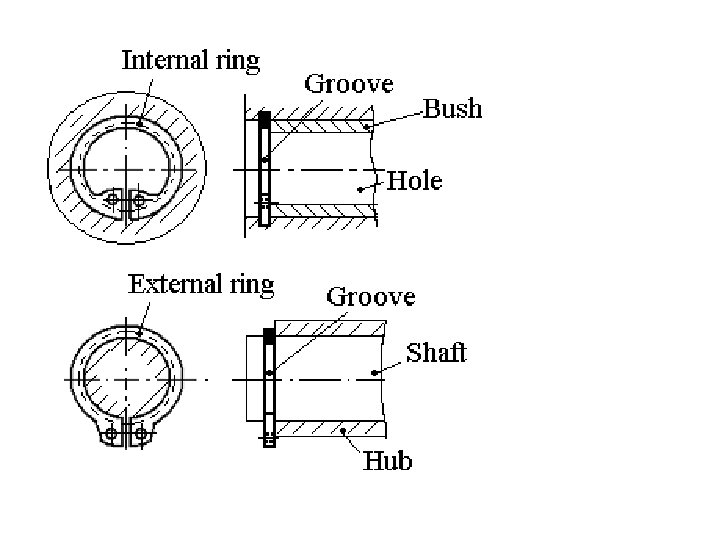
Retaining Rings • Retaining rings are placed on a shaft, in grooves in the shaft, or in a housing to prevent the axial movement of a machine element. • The amount of axial thrust load capacity and the shoulder height provided by the different ring styles also vary. External Internal External Standard retaining rings
Retaining rings applied to a water conditioner mechanism
Collars • A collar is a ring slid over the shaft and positioned adjacent to a machine element for the purpose of axial location. It is held in position, typically, by set screws. The disadvantages are the use of set screws themselves
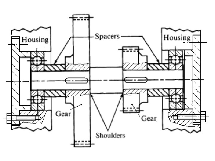
Shoulders • A shoulder is the vertical surface produced when a diameter change occurs on a shaft. Such a design is an excellent method for providing for the axial location of a machine element at least on one side.
Spacer A spacer is similar to a collar in that it is slid over the shaft against the machine element that is to be located. The primary difference is that set screws and the like are not necessary because the spacer is positioned between two elements and thus controls only the relative position between them.
Caution against Overconstraint • One practical consideration in the matter of axial location of machine elements is exercising care that elements are not overconstrained. • Under certain conditions of differential thermal expansion or with an unfavorable tolerance stack, the elements may be forced together so tightly as to cause dangerous axial stresses. • It is desirable to locate only one bearing positively on a shaft and to permit the other to float slightly in the axial direction.