Couplings Clutches and Brakes Couplings and Clutches are

Couplings, Clutches and Brakes • Couplings and Clutches are power and motion transmission elements. • They’re used to transmit power from one shaft to another shaft. • The brake is a frictional device which is used to control the motion.

Classification of Couplings

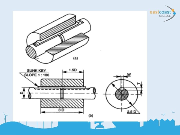
Rigid Couplings • Rigid Couplings are used to connect two shafts which are perfectly in axial alignment. Sleeve or Muff Coupling • It Is the simplest type of rigid coupling which is made from cast iron. • The hollow cylinder (muff) is fitted over the ends of the two shafts with the help of tapered sunk key. • Difficult to assemble when there is no perfect alignment.

Sleeve or Muff Couplings

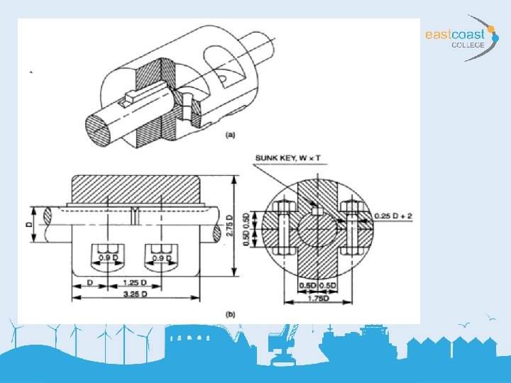
Split Muff Coupling • The muff or sleeve is made into two halves of cast iron. • Both are joined by a nut and bolt. • Assembly and disassembly of the coupling is possible without changing the position of the shaft. • This coupling is used for heavy power transmission at moderate speed.

Split and Muff Coupling

Flange Coupling • This coupling is having two separate cast iron flanges. • The flanges can be of protected type or unprotected type. • The flange couplings are rigid and accurate. • It is used for heavy power transmission at low speed.
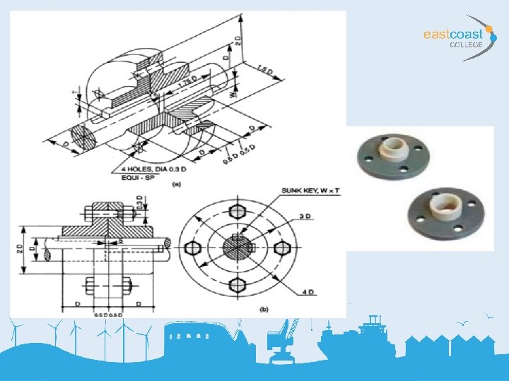

Protected Type Flange Coupling

Flexible Couplings • Flexible couplings are used to protect the driving and driven machines from effect of shocks, excessive stresses due to deflection and vibration which may arise from misalignment of shafts. Bushed pin type flange coupling • This type of coupling allows for imperfect alignment of two joining shaft. • This coupling has pins which works as a coupling bolt. The rubber or leather bushes are used over pins. • Rubber bush absorbs shocks and vibrations during operation. • It is generally used to couple electric motor and machine.

Pin Bush Type Coupling

Pin Bush Type Coupling

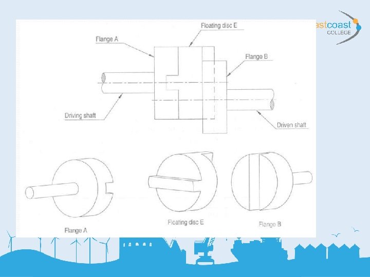
Oldham’s Coupling • Used to connect two parallel shafts whose axis are a small distance apart. • The flanges have projections and a disc is provided with two slots on both sides which are right angle to each other. • The rotation of the drive shaft causes the rotation and sliding of the disc which transmits the motion and power to the driven shaft.

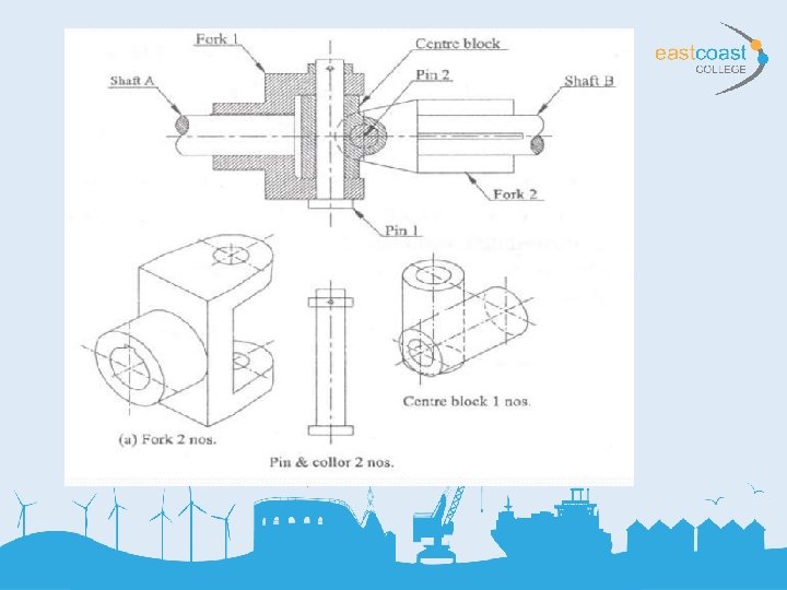
Universal Coupling • This coupling is used to connect two shafts whose axis will intersect. • The angle between the shaft axis may vary slightly during operation. • It is widely used in automobile and machine tools.

Clutches • A Clutch is a form of coupling which is used to transmit the power from a driven shaft or an input shaft to a driven shaft of machine which may be required to start or stop frequently.

Clutches

Jaw and Toothed Clutch • This type of clutch provides engagement without slippage. • The jaw clutch consists of segmental projections or dogs on one flange and corresponding recess on another. • Driving flange is rigidly attached to the end of the driving shaft while the other flange is keyed to the other shaft by feather key so it can slide onto the shaft. • The shifting device is accommodated on the hub of the sliding flange.

Jaw Toothed Clutches

Jaw and Toothed Clutch

Disc Clutch • Consists of 2 flanges, one rigidly keyed to driving shafts and other fitted to driven shaft by feather key or splines. • The amount of torque transmitted depends upon axial pressure, radius of the friction surfaces and coefficient of friction. • Used in particular when large amounts of torque transmission is required.

Disc Clutch

Disc Clutch

Cone Clutch • Consists of an internal cone fixed to the driving member and a moveable cone free to slide axially and keyed to the driven member. • The slope of cone is 8 -15 degrees. • The clutch parts are help together by springs producing required axial force. • Advantage of cone clutch over disc clutch is very simple and required less axial pressure to disengage the clutch.

Cone Clutch

Cone Clutch

Cone Clutch

Centrifugal Clutch • Engagement and disengagement takes place at a certain running speed. • The shoes and held against the hub or spider on the driving shaft by means of suitable springs. • The driven member consists of a cylindrical drum in which shoes slide to make the contact through friction surfaces with inner linings of drum due to centrifugal force on the shoes.

Centrifugal Clutch

Brakes • It is a device by means of which frictional resistance is applied to a moving machine member in order to retard or stop the motion of machine. • Brakes are used in automobiles, trains, vehicles, hoists, elevators, presses, etc. • Brakes absorbs kinetic energy of moving member in automobiles and brakes absorbs potential energy of lowering member in hoists or elevator brake.

Brakes

Block Brake • This Brake consists of blocks which are pressed against the rim of revolving brake wheel or drum. • The friction between the wheel and the blocks tend to prevent the rotation of the wheel. • Examples, single block, railway train, tram. • Double block, electric cranes, bicycle brake.

Block Brakes

Block Brakes

Block Brakes

Band Brake • A band brake consists of a flexible band of leather or steel lined with friction material. • The friction between the band the wheel surface provides the braking force to decrease or stop the motion of the wheel. • This type of brakes are used in civil construction equipment and is used in automobiles as a handbrake.

Simple Band Brakes

Differential Band Brakes

Internal Expanding Shoe Brake • The shoes are housed in the rotating drum. • Disengaged there is sufficient gap between shoes and inner surface of the drum. • The rotation of the cam tends to expand the shoes outwards eliminating the gap and making contact with the inner surface of the drum. • Used in automobiles

Drum Brakes

Drum Brakes
- Slides: 44