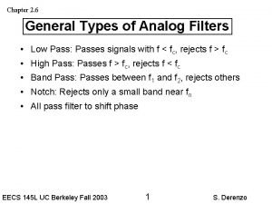
Chapter 12 Filters and Tuned Amplifiers 12 1
- Slides: 51
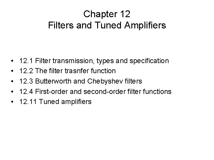
Chapter 12 Filters and Tuned Amplifiers • • • 12. 1 Filter transmission, types and specification 12. 2 The filter trasnfer function 12. 3 Butterworth and Chebyshev filters 12. 4 First-order and second-order filter functions 12. 11 Tuned amplifiers
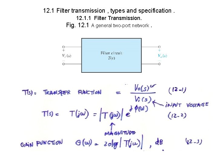
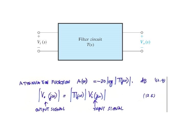
12. 1 Filter transmission , types and specification. 12. 1. 1 Filter Transmission. Fig. 12. 1 A general two-port network.
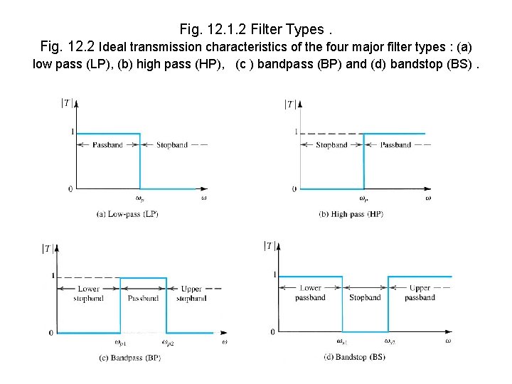
Fig. 12. 1. 2 Filter Types. Fig. 12. 2 Ideal transmission characteristics of the four major filter types : (a) low pass (LP), (b) high pass (HP), (c ) bandpass (BP) and (d) bandstop (BS).
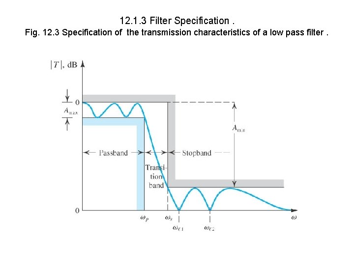
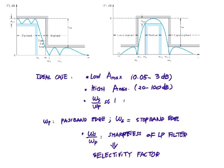
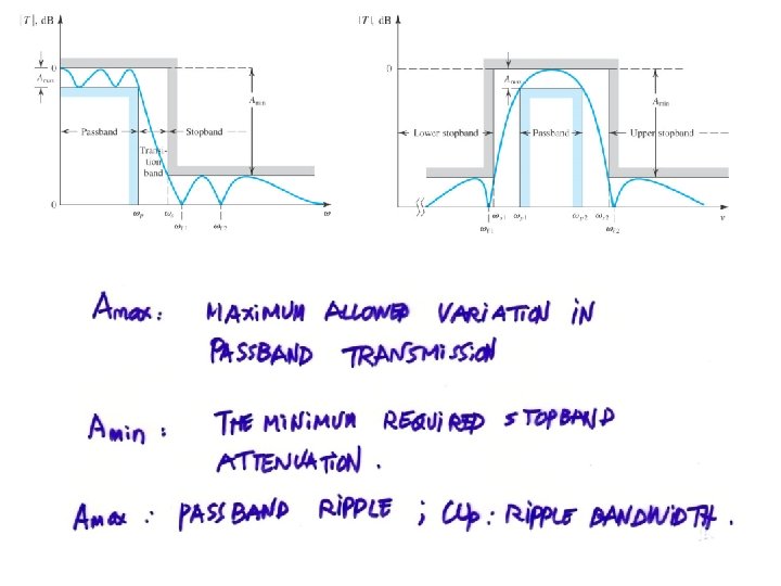
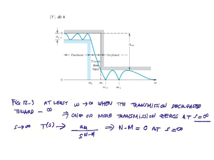
12. 1. 3 Filter Specification. Fig. 12. 3 Specification of the transmission characteristics of a low pass filter.
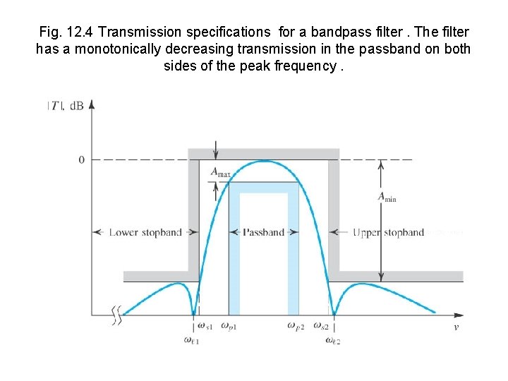
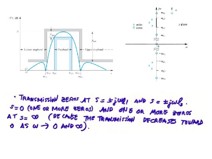
Fig. 12. 4 Transmission specifications for a bandpass filter. The filter has a monotonically decreasing transmission in the passband on both sides of the peak frequency.
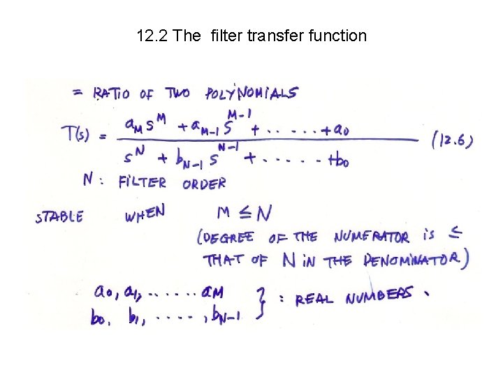
12. 2 The filter transfer function
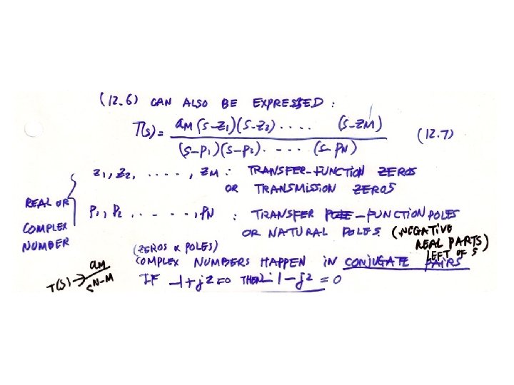
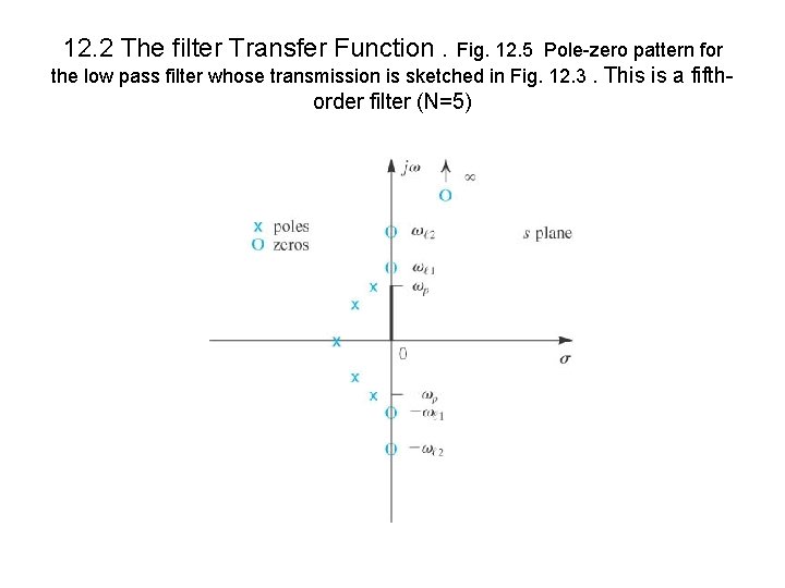
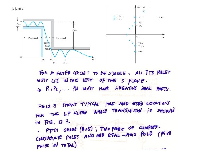
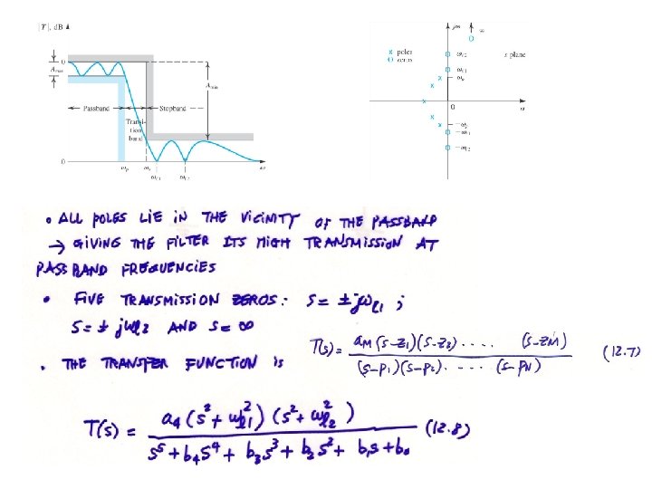
12. 2 The filter Transfer Function. Fig. 12. 5 Pole-zero pattern for the low pass filter whose transmission is sketched in Fig. 12. 3. This is a fifth- order filter (N=5)
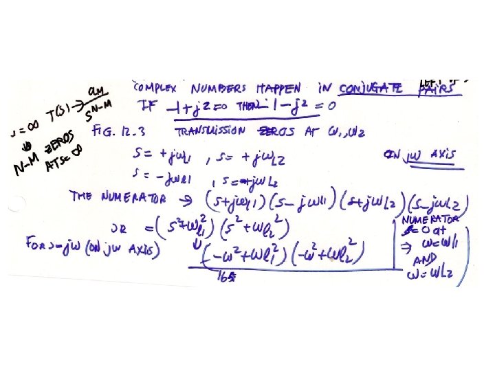
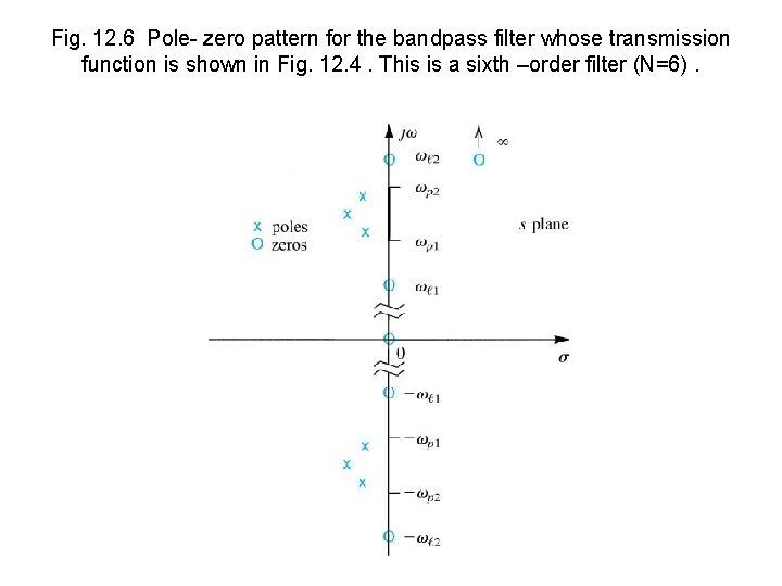
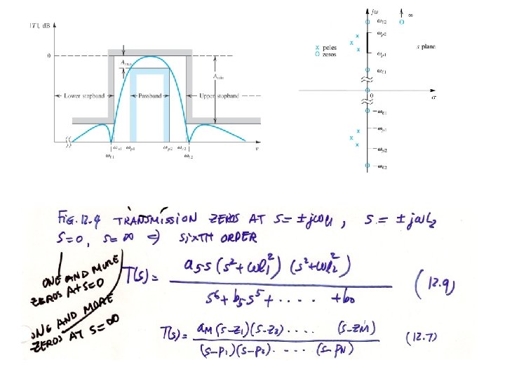
Fig. 12. 6 Pole- zero pattern for the bandpass filter whose transmission function is shown in Fig. 12. 4. This is a sixth –order filter (N=6).
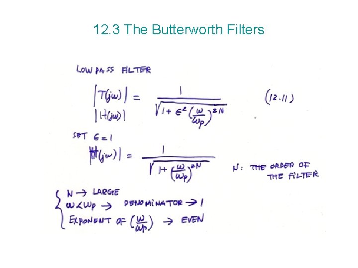
12. 3 The Butterworth Filters
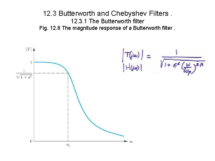
12. 3 Butterworth and Chebyshev Filters. 12. 3. 1 The Butterworth filter Fig. 12. 8 The magnitude response of a Butterworth filter.
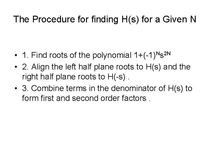
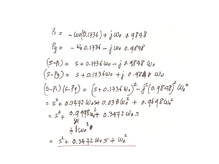
The Procedure for finding H(s) for a Given N • 1. Find roots of the polynomial 1+(-1)Ns 2 N • 2. Align the left half plane roots to H(s) and the right half plane roots to H(-s). • 3. Combine terms in the denominator of H(s) to form first and second order factors.
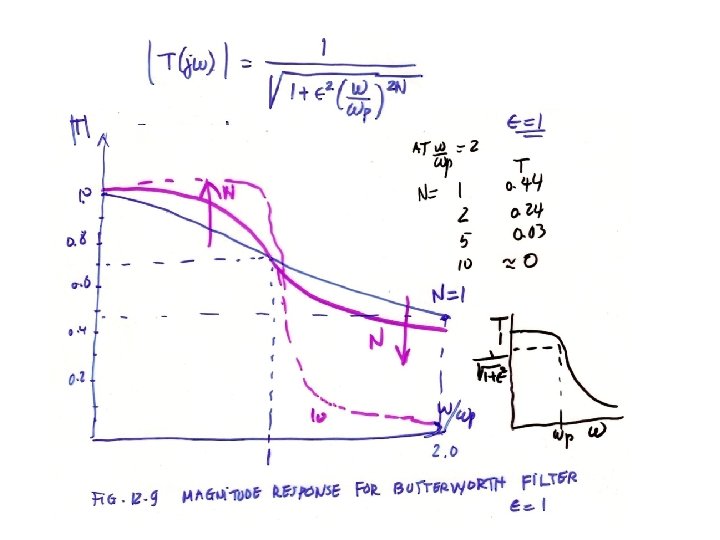
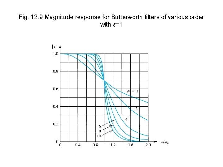
Fig. 12. 9 Magnitude response for Butterworth filters of various order with ε=1
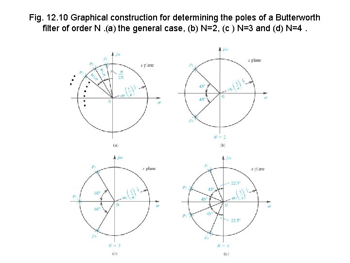
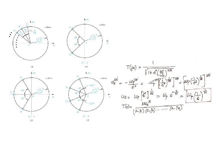
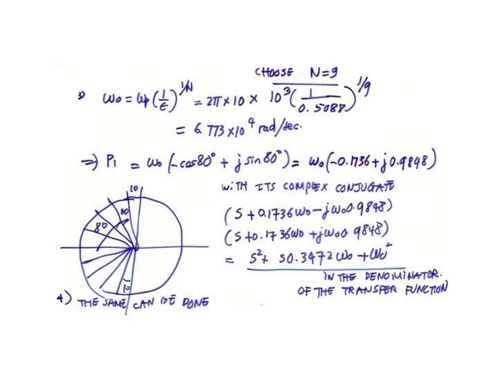
Fig. 12. 10 Graphical construction for determining the poles of a Butterworth filter of order N. (a) the general case, (b) N=2, (c ) N=3 and (d) N=4.
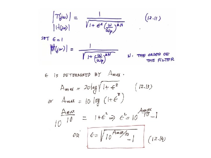
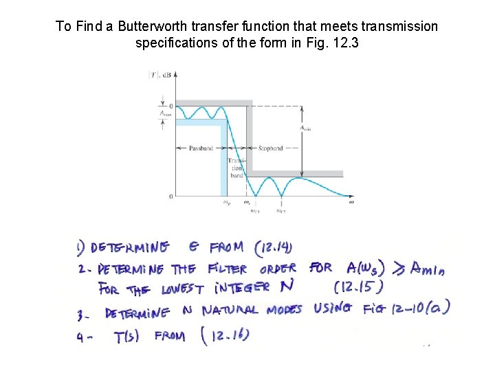
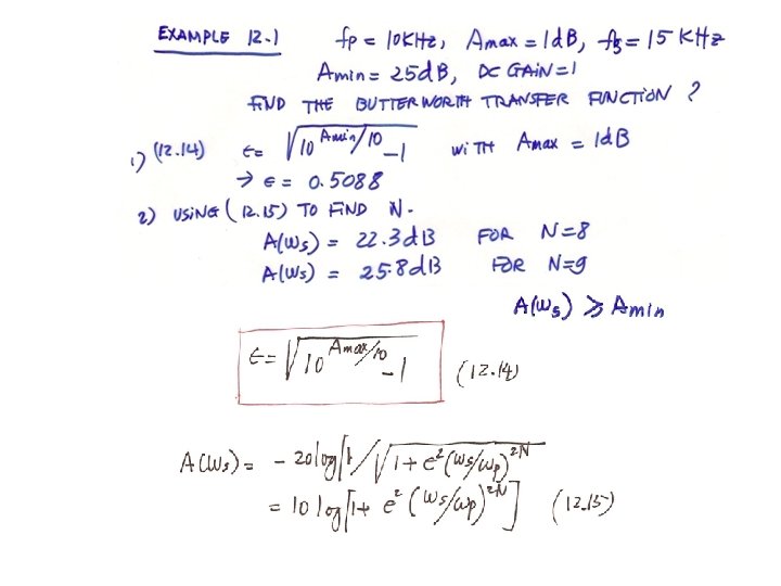
To Find a Butterworth transfer function that meets transmission specifications of the form in Fig. 12. 3
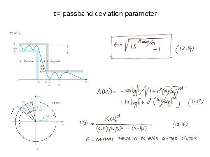
ε= passband deviation parameter
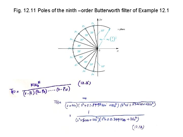
Fig. 12. 11 Poles of the ninth –order Butterworth filter of Example 12. 1
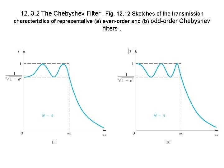
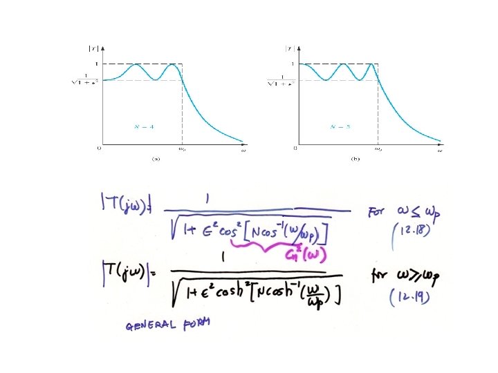
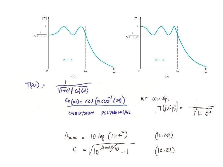
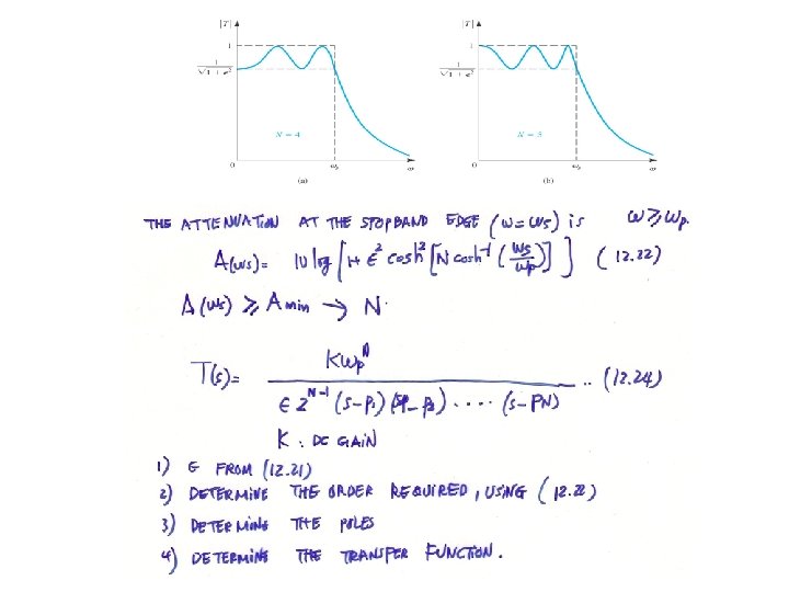
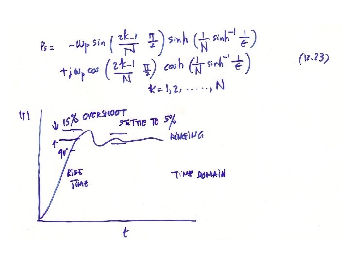
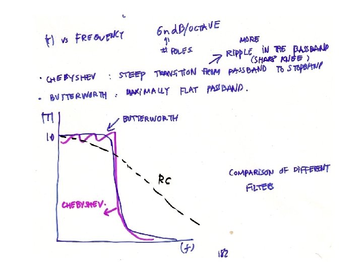
12. 3. 2 The Chebyshev Filter. Fig. 12 Sketches of the transmission characteristics of representative (a) even-order and (b) odd-order Chebyshev filters.
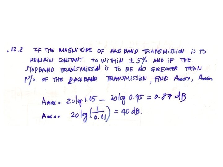
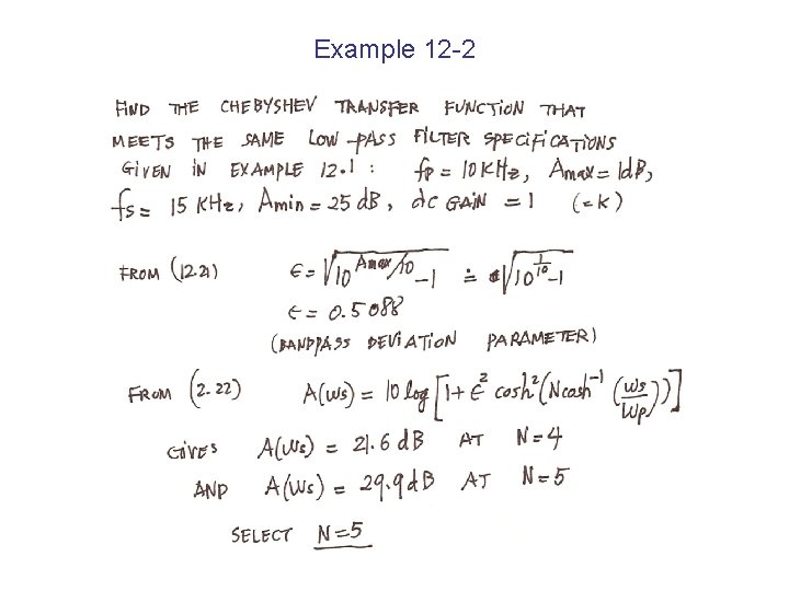
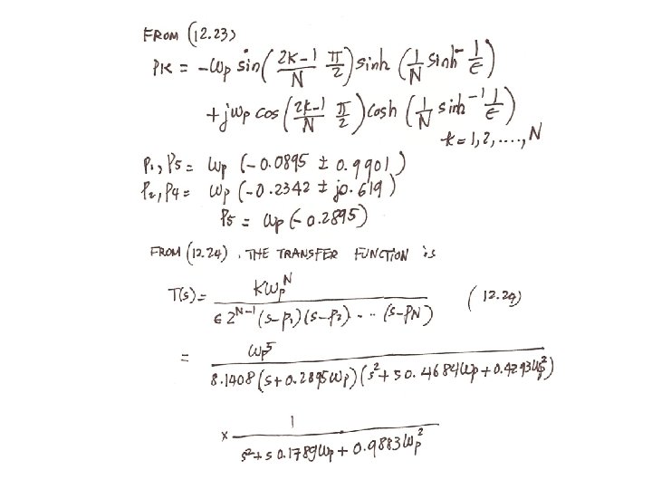
Example 12 -2
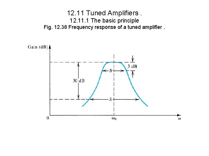
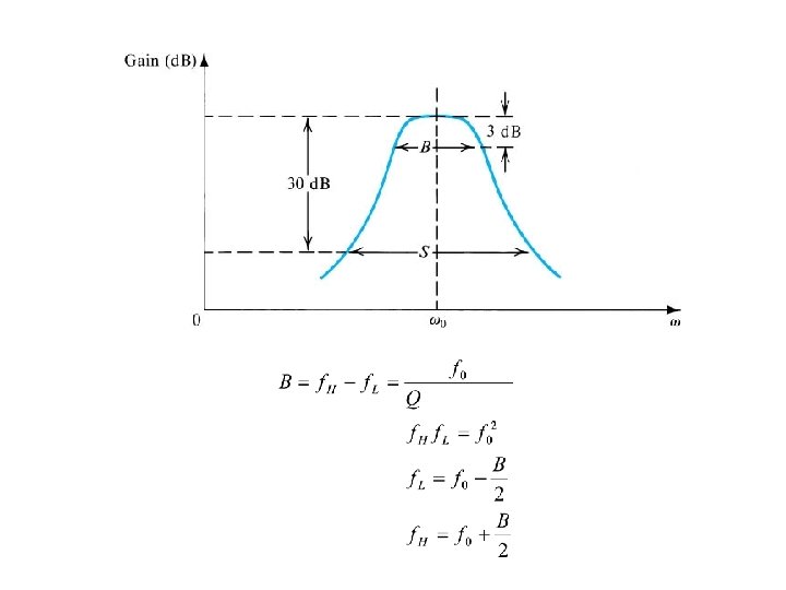
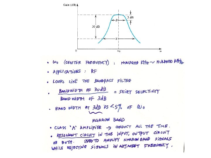
12. 11 Tuned Amplifiers. 12. 11. 1 The basic principle Fig. 12. 38 Frequency response of a tuned amplifier.