Chapter 10 Sound in Ducts Slides to accompany



- Slides: 49
Chapter 10 – Sound in Ducts Slides to accompany lectures in Vibro-Acoustic Design in Mechanical Systems © 2012 by D. W. Herrin Department of Mechanical Engineering University of Kentucky Lexington, KY 40506 -0503 Tel: 859 -218 -0609 dherrin@engr. uky. edu
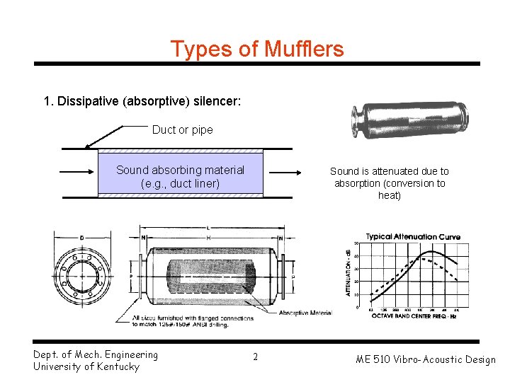
Types of Mufflers 1. Dissipative (absorptive) silencer: Duct or pipe Sound absorbing material (e. g. , duct liner) Dept. of Mech. Engineering University of Kentucky Sound is attenuated due to absorption (conversion to heat) 2 ME 510 Vibro-Acoustic Design
Types of Mufflers 2. Reactive muffler: Sound is attenuated by reflection and “cancellation” of sound waves Compressor discharge details 40 mm Dept. of Mech. Engineering University of Kentucky 3 ME 510 Vibro-Acoustic Design
Types of Mufflers 3. Combination reactive and dissipative muffler: Sound absorbing material Perforated tubes Sound is attenuated by reflection and “cancellation” of sound waves + absorption of sound Dept. of Mech. Engineering University of Kentucky 4 ME 510 Vibro-Acoustic Design
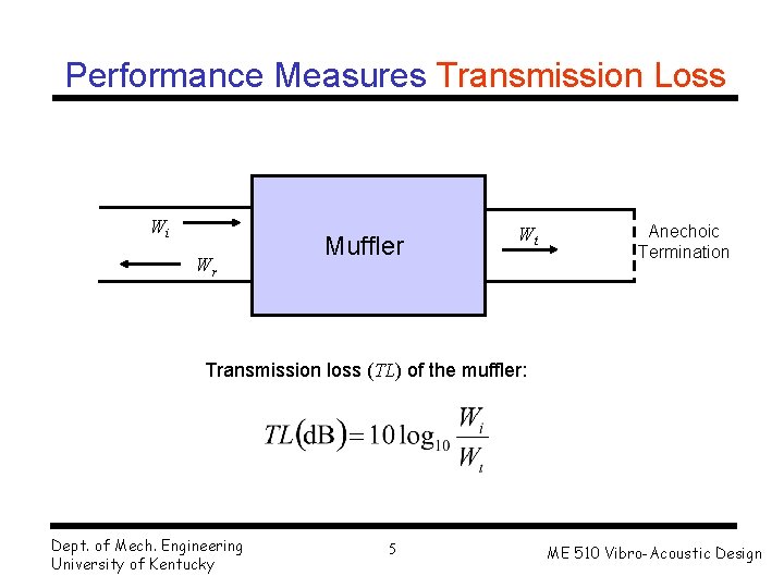
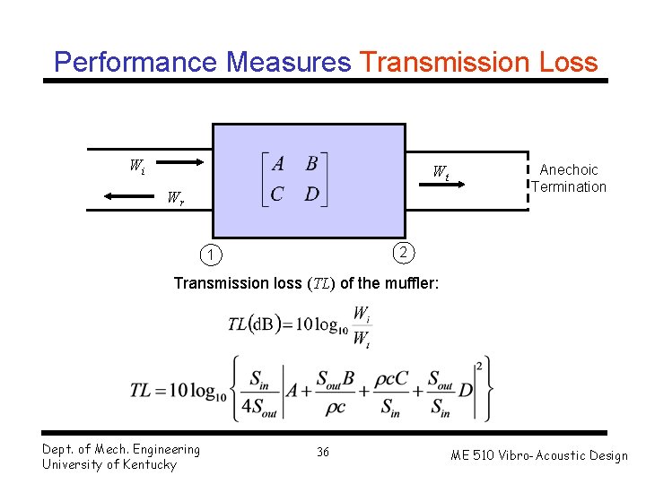
Performance Measures Transmission Loss Wi Wr Muffler Wt Anechoic Termination Transmission loss (TL) of the muffler: Dept. of Mech. Engineering University of Kentucky 5 ME 510 Vibro-Acoustic Design
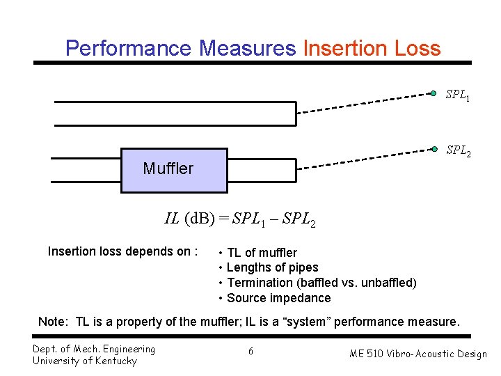
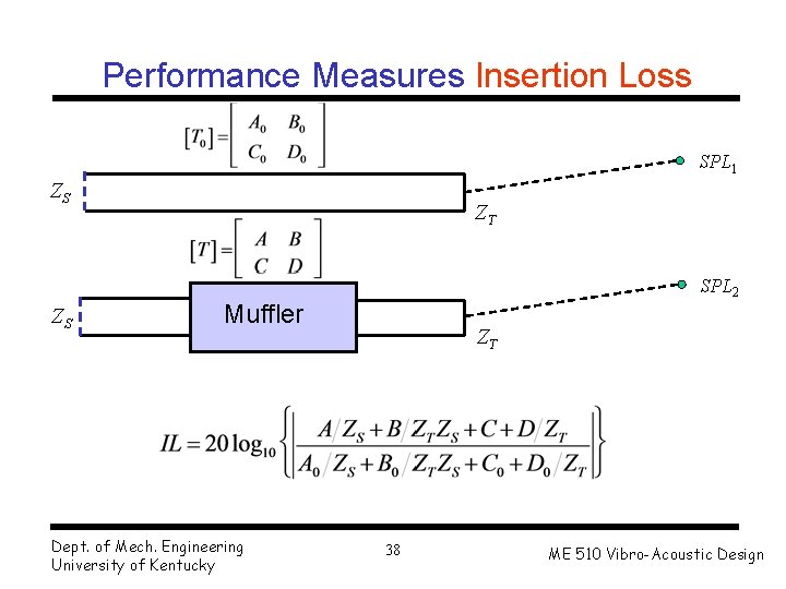
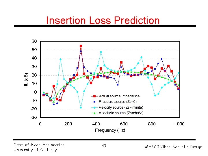
Performance Measures Insertion Loss SPL 1 SPL 2 Muffler IL (d. B) = SPL 1 – SPL 2 Insertion loss depends on : • TL of muffler • Lengths of pipes • Termination (baffled vs. unbaffled) • Source impedance Note: TL is a property of the muffler; IL is a “system” performance measure. Dept. of Mech. Engineering University of Kentucky 6 ME 510 Vibro-Acoustic Design
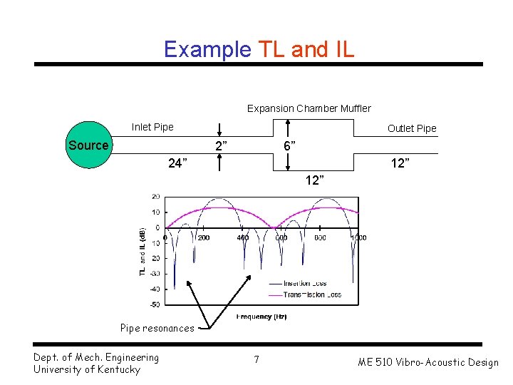
Example TL and IL Expansion Chamber Muffler Inlet Pipe Source Outlet Pipe 2” 6” 24” 12” Pipe resonances Dept. of Mech. Engineering University of Kentucky 7 ME 510 Vibro-Acoustic Design
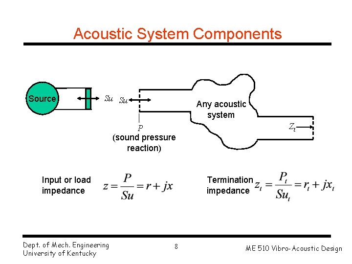
Acoustic System Components Source Su Su Any acoustic system Zt P (sound pressure reaction) Input or load impedance Dept. of Mech. Engineering University of Kentucky Termination impedance 8 ME 510 Vibro-Acoustic Design
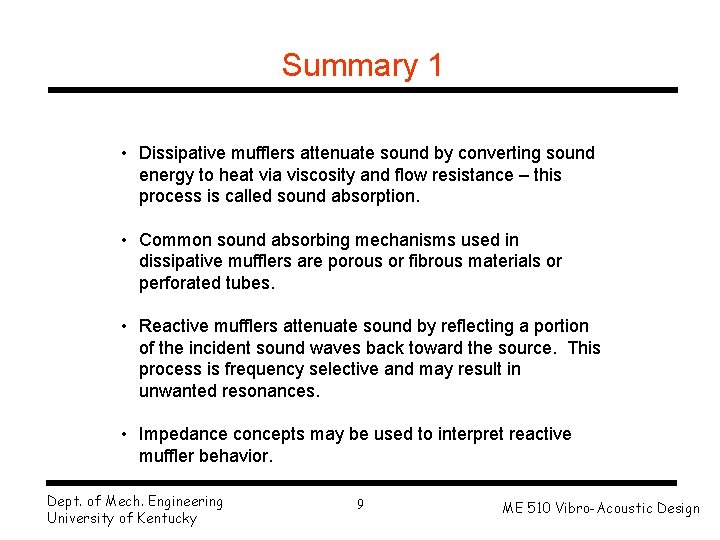
Summary 1 • Dissipative mufflers attenuate sound by converting sound energy to heat via viscosity and flow resistance – this process is called sound absorption. • Common sound absorbing mechanisms used in dissipative mufflers are porous or fibrous materials or perforated tubes. • Reactive mufflers attenuate sound by reflecting a portion of the incident sound waves back toward the source. This process is frequency selective and may result in unwanted resonances. • Impedance concepts may be used to interpret reactive muffler behavior. Dept. of Mech. Engineering University of Kentucky 9 ME 510 Vibro-Acoustic Design
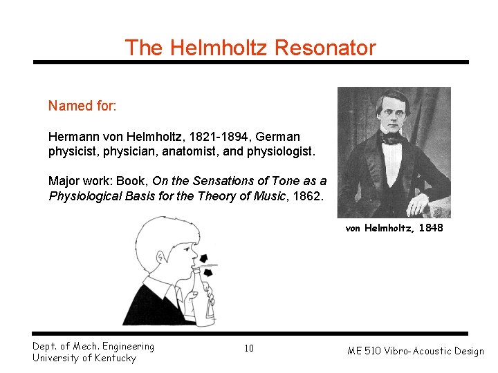
The Helmholtz Resonator Named for: Hermann von Helmholtz, 1821 -1894, German physicist, physician, anatomist, and physiologist. Major work: Book, On the Sensations of Tone as a Physiological Basis for the Theory of Music, 1862. von Helmholtz, 1848 Dept. of Mech. Engineering University of Kentucky 10 ME 510 Vibro-Acoustic Design
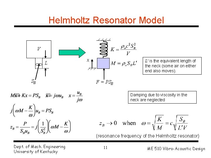
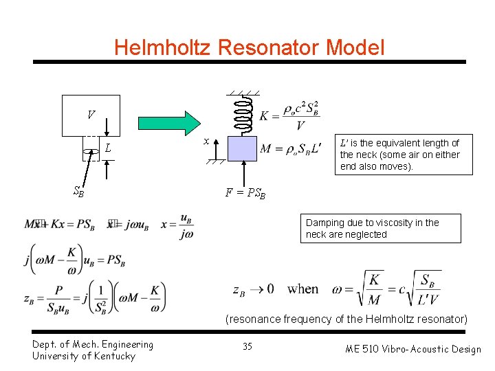
Helmholtz Resonator Model V L SB x L’ is the equivalent length of the neck (some air on either end also moves). F = PSB Damping due to viscosity in the neck are neglected (resonance frequency of the Helmholtz resonator) Dept. of Mech. Engineering University of Kentucky 11 ME 510 Vibro-Acoustic Design
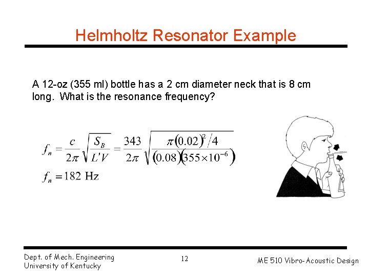
Helmholtz Resonator Example A 12 -oz (355 ml) bottle has a 2 cm diameter neck that is 8 cm long. What is the resonance frequency? Dept. of Mech. Engineering University of Kentucky 12 ME 510 Vibro-Acoustic Design
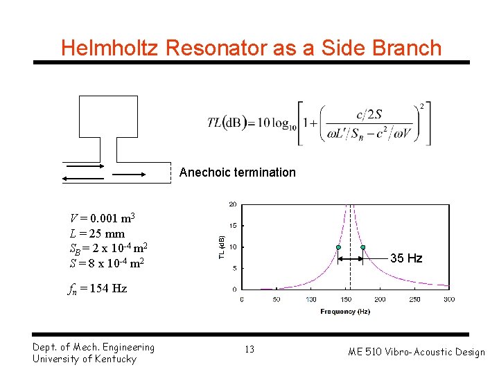
Helmholtz Resonator as a Side Branch Anechoic termination V = 0. 001 m 3 L = 25 mm SB = 2 x 10 -4 m 2 S = 8 x 10 -4 m 2 35 Hz fn = 154 Hz Dept. of Mech. Engineering University of Kentucky 13 ME 510 Vibro-Acoustic Design
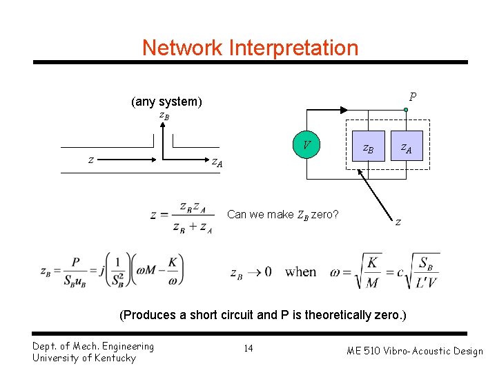
Network Interpretation P (any system) z. B V z z. A Can we make ZB zero? z. A z. B z (Produces a short circuit and P is theoretically zero. ) Dept. of Mech. Engineering University of Kentucky 14 ME 510 Vibro-Acoustic Design
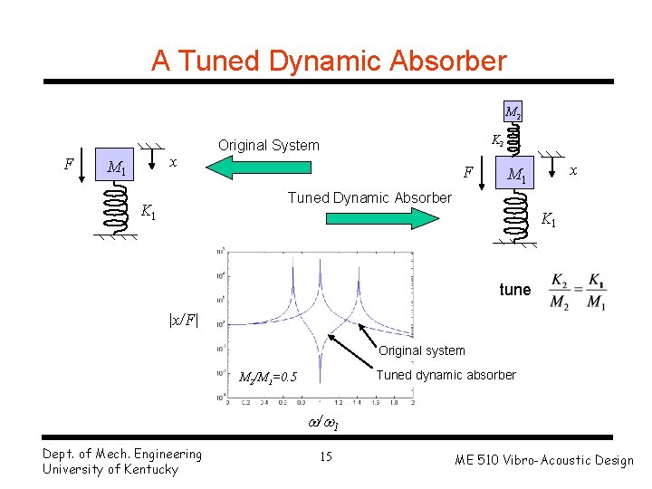
A Tuned Dynamic Absorber M 2 F x M 1 K 2 Original System F x M 1 Tuned Dynamic Absorber K 1 tune |x/F| Original system Tuned dynamic absorber M 2/M 1=0. 5 / 1 Dept. of Mech. Engineering University of Kentucky 15 ME 510 Vibro-Acoustic Design
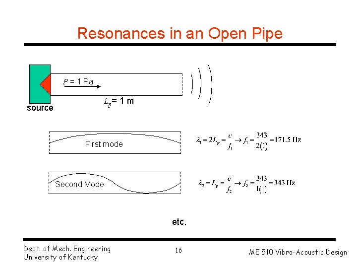
Resonances in an Open Pipe P = 1 Pa source Lp = 1 m First mode Second Mode etc. Dept. of Mech. Engineering University of Kentucky 16 ME 510 Vibro-Acoustic Design
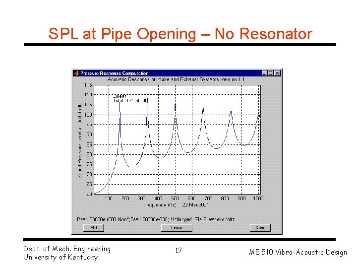
SPL at Pipe Opening – No Resonator Dept. of Mech. Engineering University of Kentucky 17 ME 510 Vibro-Acoustic Design
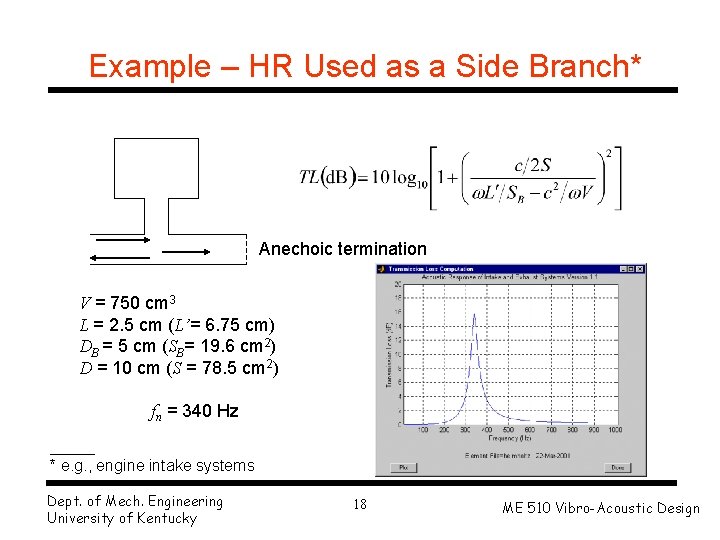
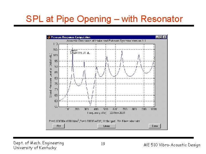
Example – HR Used as a Side Branch* Anechoic termination V = 750 cm 3 L = 2. 5 cm (L’= 6. 75 cm) DB = 5 cm (SB= 19. 6 cm 2) D = 10 cm (S = 78. 5 cm 2) fn = 340 Hz _____ * e. g. , engine intake systems Dept. of Mech. Engineering University of Kentucky 18 ME 510 Vibro-Acoustic Design
SPL at Pipe Opening – with Resonator Dept. of Mech. Engineering University of Kentucky 19 ME 510 Vibro-Acoustic Design
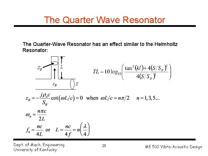
The Quarter Wave Resonator The Quarter-Wave Resonator has an effect similar to the Helmholtz Resonator: L SB z. B Dept. of Mech. Engineering University of Kentucky S 20 ME 510 Vibro-Acoustic Design
Summary 2 • The side-branch resonator is analogous to the tuned dynamic absorber. • Resonators used as side branches attenuate sound in the main duct or pipe. • The transmission loss is confined over a relatively narrow band of frequencies centered at the natural frequency of the resonator. Dept. of Mech. Engineering University of Kentucky 21 ME 510 Vibro-Acoustic Design
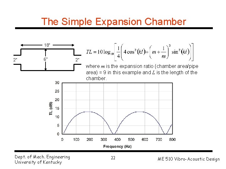
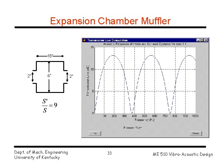
The Simple Expansion Chamber 18” 2” 6” 2” where m is the expansion ratio (chamber area/pipe area) = 9 in this example and L is the length of the chamber. Dept. of Mech. Engineering University of Kentucky 22 ME 510 Vibro-Acoustic Design
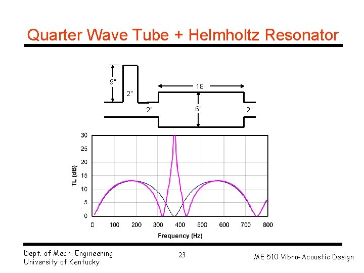
Quarter Wave Tube + Helmholtz Resonator 9” 18” 2” 6” 2” Dept. of Mech. Engineering University of Kentucky 23 2” ME 510 Vibro-Acoustic Design
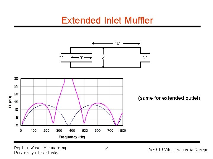
Extended Inlet Muffler 18” 2” 9” 6” 2” (same for extended outlet) Dept. of Mech. Engineering University of Kentucky 24 ME 510 Vibro-Acoustic Design
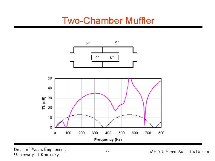
Two-Chamber Muffler 9” 9” 4” Dept. of Mech. Engineering University of Kentucky 6” 25 ME 510 Vibro-Acoustic Design
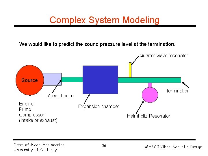
Complex System Modeling We would like to predict the sound pressure level at the termination. Quarter-wave resonator Source termination Area change Engine Pump Compressor (intake or exhaust) Dept. of Mech. Engineering University of Kentucky Expansion chamber Helmholtz Resonator 26 ME 510 Vibro-Acoustic Design
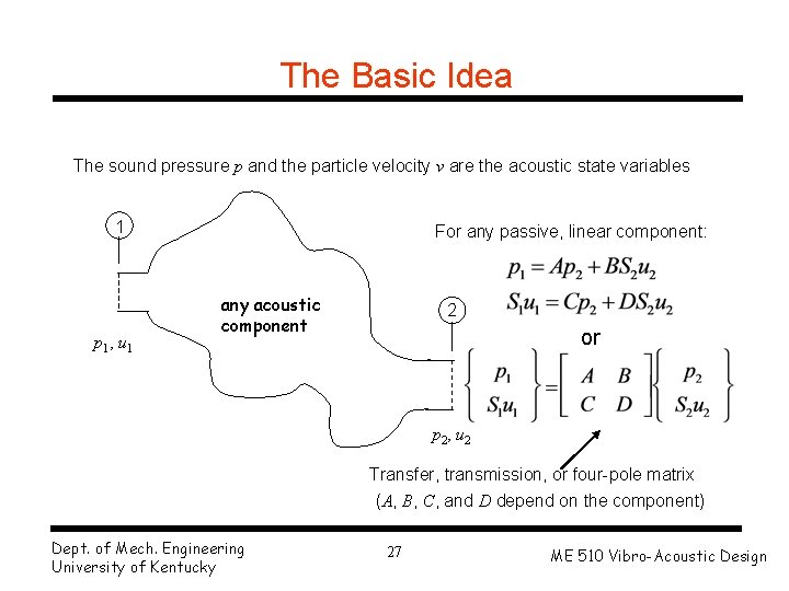
The Basic Idea The sound pressure p and the particle velocity v are the acoustic state variables 1 p 1, u 1 For any passive, linear component: any acoustic component 2 or p 2, u 2 Transfer, transmission, or four-pole matrix (A, B, C, and D depend on the component) Dept. of Mech. Engineering University of Kentucky 27 ME 510 Vibro-Acoustic Design
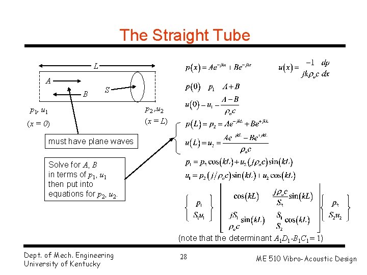
The Straight Tube L A B S p 1, u 1 p 2 , u 2 (x = 0) (x = L) must have plane waves Solve for A, B in terms of p 1, u 1 then put into equations for p 2, u 2. (note that the determinant A 1 D 1 -B 1 C 1 = 1) Dept. of Mech. Engineering University of Kentucky 28 ME 510 Vibro-Acoustic Design
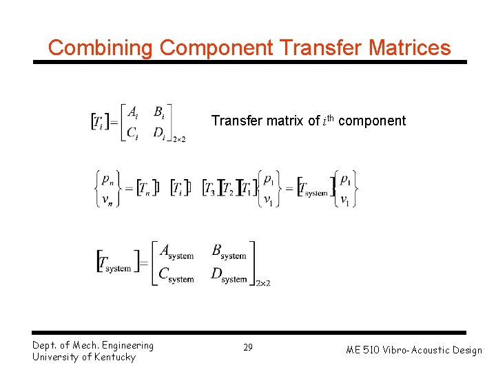
Combining Component Transfer Matrices Transfer matrix of ith component Dept. of Mech. Engineering University of Kentucky 29 ME 510 Vibro-Acoustic Design
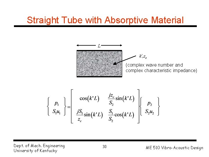
Straight Tube with Absorptive Material L k’, zc (complex wave number and complex characteristic impedance) Dept. of Mech. Engineering University of Kentucky 30 ME 510 Vibro-Acoustic Design
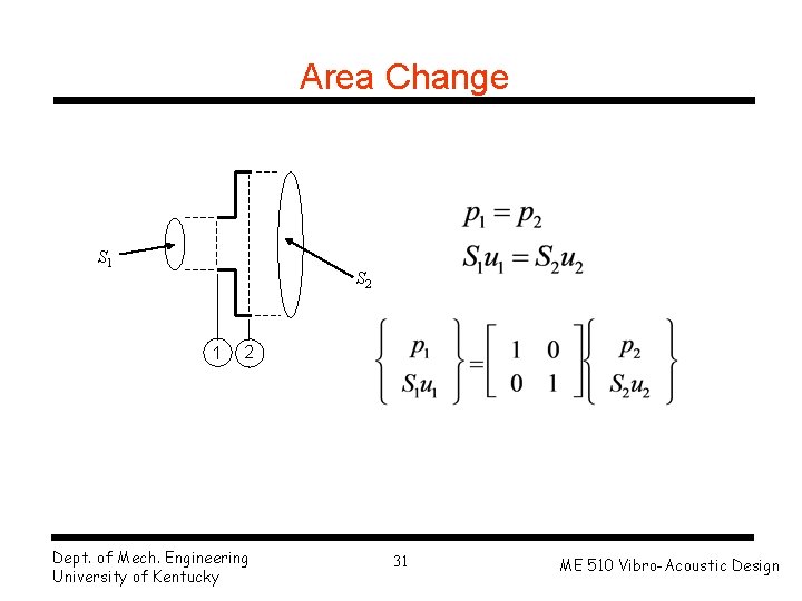
Area Change S 1 S 2 1 2 Dept. of Mech. Engineering University of Kentucky 31 ME 510 Vibro-Acoustic Design
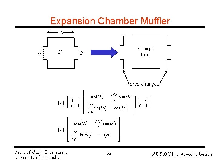
Expansion Chamber Muffler L S S’ straight tube S area changes Dept. of Mech. Engineering University of Kentucky 32 ME 510 Vibro-Acoustic Design
Expansion Chamber Muffler 18” 2” 6” Dept. of Mech. Engineering University of Kentucky 2” 33 ME 510 Vibro-Acoustic Design
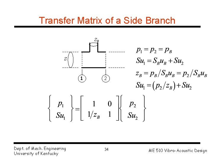
Transfer Matrix of a Side Branch SB S 1 Dept. of Mech. Engineering University of Kentucky 2 34 ME 510 Vibro-Acoustic Design
Helmholtz Resonator Model V L SB x L’ is the equivalent length of the neck (some air on either end also moves). F = PSB Damping due to viscosity in the neck are neglected (resonance frequency of the Helmholtz resonator) Dept. of Mech. Engineering University of Kentucky 35 ME 510 Vibro-Acoustic Design
Performance Measures Transmission Loss Wi Wt Wr Anechoic Termination 2 1 Transmission loss (TL) of the muffler: Dept. of Mech. Engineering University of Kentucky 36 ME 510 Vibro-Acoustic Design
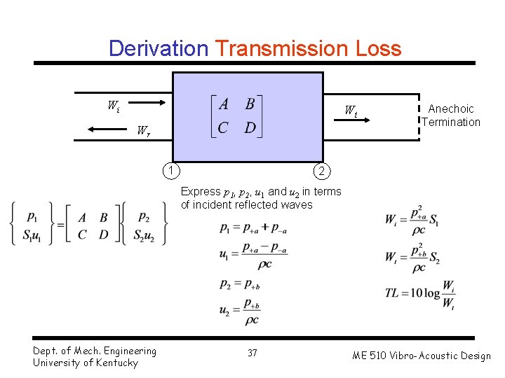
Derivation Transmission Loss Wi Wt Wr 1 Anechoic Termination 2 Express p 1, p 2, u 1 and u 2 in terms of incident reflected waves Dept. of Mech. Engineering University of Kentucky 37 ME 510 Vibro-Acoustic Design
Performance Measures Insertion Loss SPL 1 ZS ZS ZT SPL 2 Muffler Dept. of Mech. Engineering University of Kentucky ZT 38 ME 510 Vibro-Acoustic Design
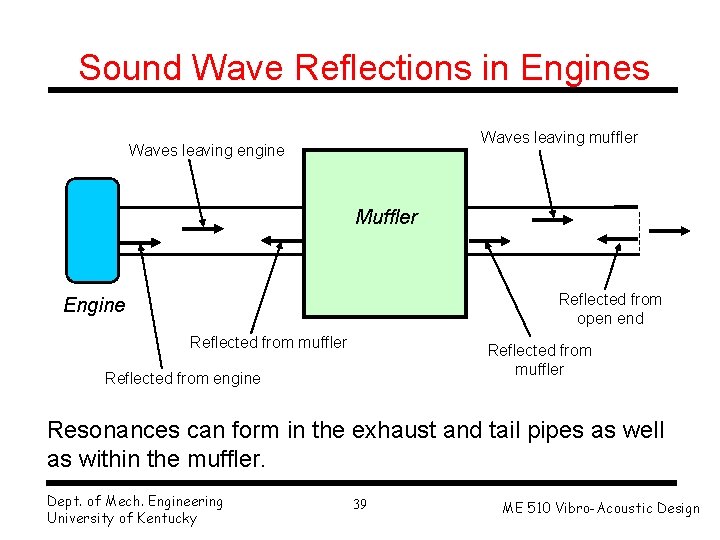
Sound Wave Reflections in Engines Waves leaving muffler Waves leaving engine Muffler Reflected from open end Engine Reflected from muffler Reflected from engine Resonances can form in the exhaust and tail pipes as well as within the muffler. Dept. of Mech. Engineering University of Kentucky 39 ME 510 Vibro-Acoustic Design
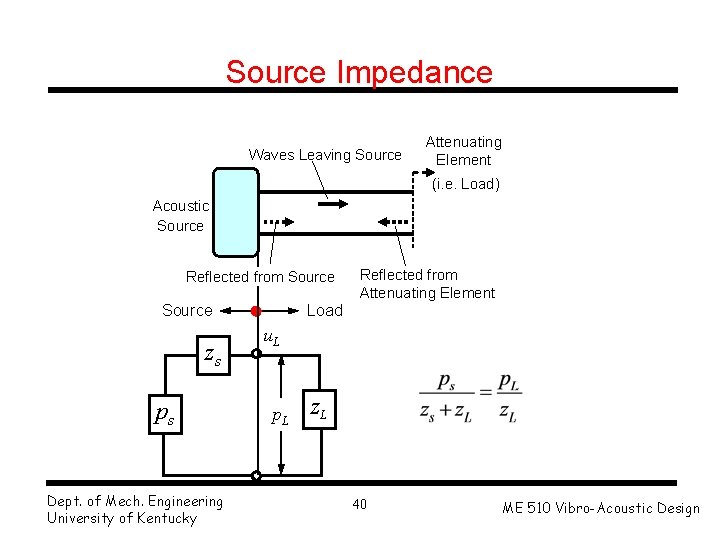
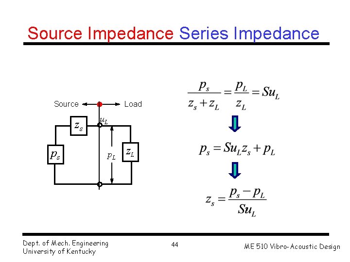
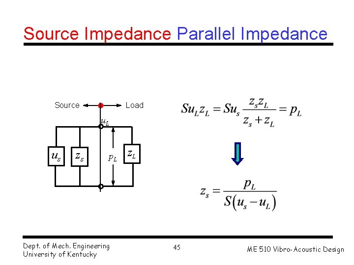
Source Impedance Waves Leaving Source Attenuating Element (i. e. Load) Acoustic Source Reflected from Source zs ps Dept. of Mech. Engineering University of Kentucky Reflected from Attenuating Element Load u. L p. L z. L 40 ME 510 Vibro-Acoustic Design
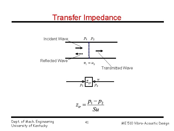
Transfer Impedance Incident Wave Reflected Wave Transmitted Wave ztr Dept. of Mech. Engineering University of Kentucky 41 ME 510 Vibro-Acoustic Design
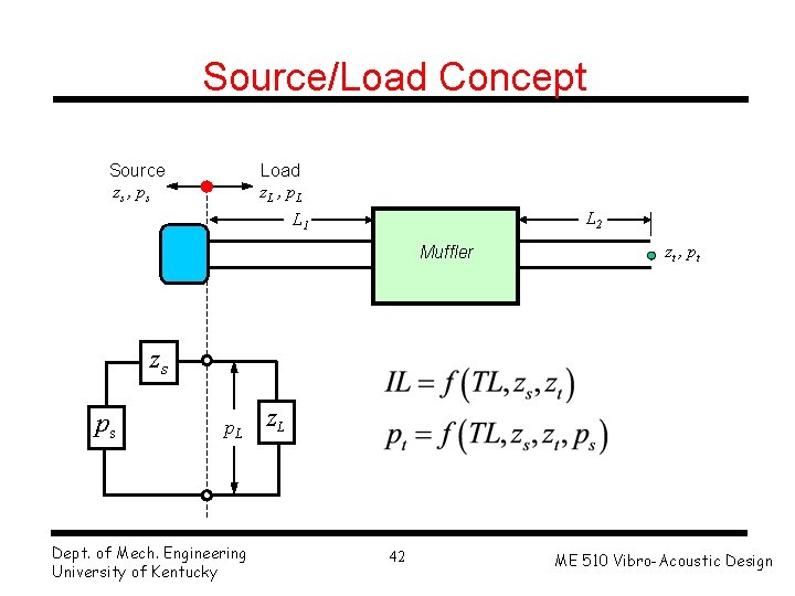
Source/Load Concept Source zs , ps Load z. L , p. L L 2 L 1 Muffler zt , pt zs ps p. L Dept. of Mech. Engineering University of Kentucky z. L 42 ME 510 Vibro-Acoustic Design
Insertion Loss Prediction Dept. of Mech. Engineering University of Kentucky 43 ME 510 Vibro-Acoustic Design
Source Impedance Series Impedance Source zs ps Load u. L p. L Dept. of Mech. Engineering University of Kentucky z. L 44 ME 510 Vibro-Acoustic Design
Source Impedance Parallel Impedance Source Load u. L us zs p. L Dept. of Mech. Engineering University of Kentucky z. L 45 ME 510 Vibro-Acoustic Design
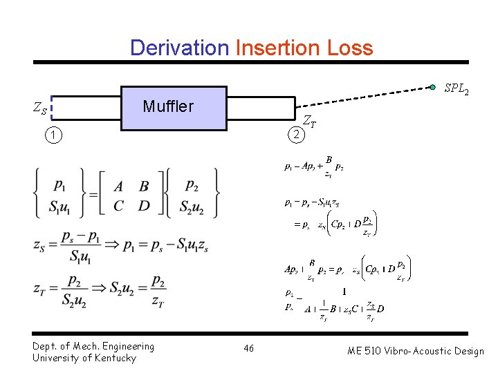
Derivation Insertion Loss SPL 2 Muffler ZS 2 1 Dept. of Mech. Engineering University of Kentucky 46 ZT ME 510 Vibro-Acoustic Design
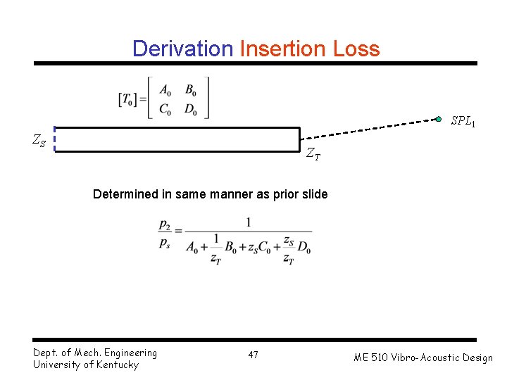
Derivation Insertion Loss SPL 1 ZS ZT Determined in same manner as prior slide Dept. of Mech. Engineering University of Kentucky 47 ME 510 Vibro-Acoustic Design
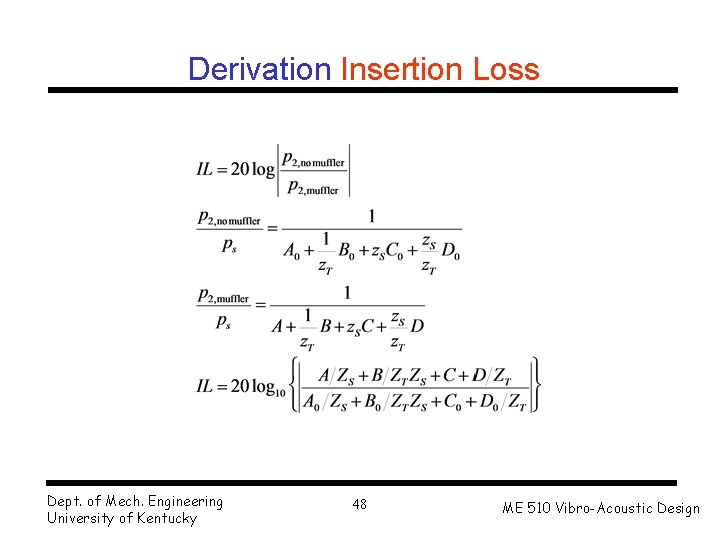
Derivation Insertion Loss Dept. of Mech. Engineering University of Kentucky 48 ME 510 Vibro-Acoustic Design
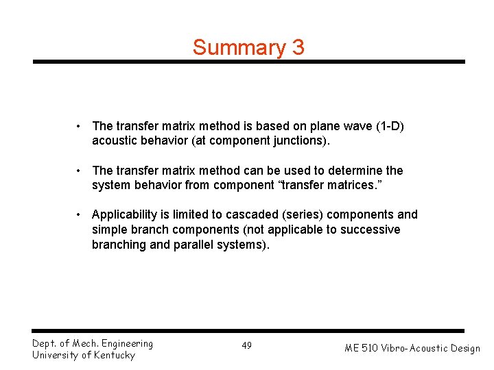
Summary 3 • The transfer matrix method is based on plane wave (1 -D) acoustic behavior (at component junctions). • The transfer matrix method can be used to determine the system behavior from component “transfer matrices. ” • Applicability is limited to cascaded (series) components and simple branch components (not applicable to successive branching and parallel systems). Dept. of Mech. Engineering University of Kentucky 49 ME 510 Vibro-Acoustic Design