Boolean Algebra Examples No 1 De Morgans Theorem


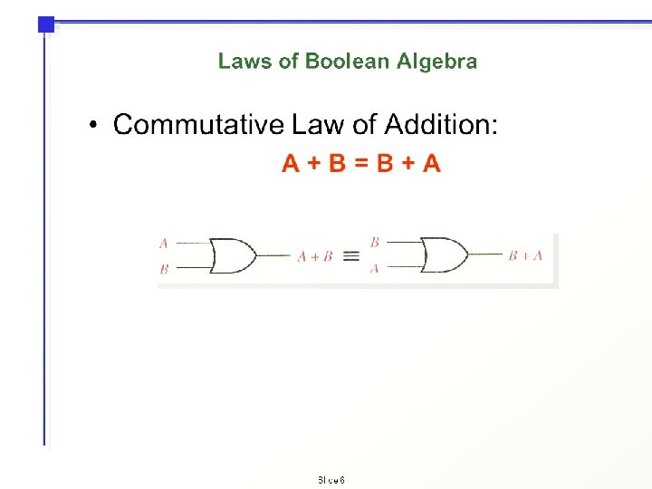
Boolean Algebra Examples No 1
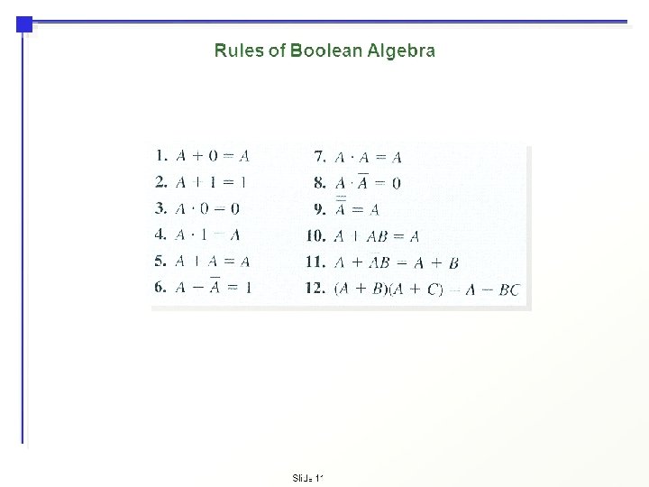

De. Morgan’s Theorem • De. Morgan´s Theorem and Laws can be used to to find the equivalency of the NAND and NOR gates • De. Morgan’s First Law Implementation using Logic Gates

• The top logic gate arrangement of: A. B can be implemented using a standard NAND gate with inputs A and B. The lower logic gate arrangement first inverts the two inputs producing A and B. These then become the inputs to the OR gate. Therefore the output from the OR gate becomes: A+B • Then we can see here that a standard OR gate function with inverters (NOT gates) on each of its inputs is equivalent to a NAND gate function. So an individual NAND gate can be represented in this way as the equivalency of a NAND gate is a negative-OR.

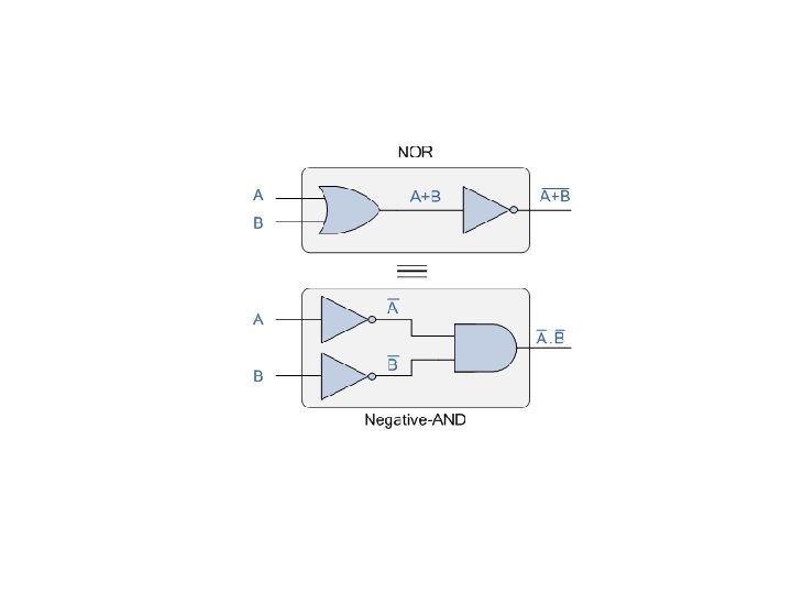
• De. Morgan’s Second Theorem • De. Morgan’s Second theorem proves that when two (or more) input variables are OR’ed and negated, they are equivalent to the AND of the complements of the individual variables. Thus the equivalent of the NOR function is a negative-AND function proving that A+B = A. B, and again we can show operation this using the following truth table.

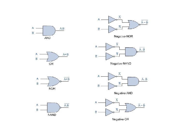
• Although we have used De. Morgan’s theorems with only two input variables A and B, they are equally valid for use with three, four or more input variable expressions, for example: • Thus to obtain the De. Morgan equivalent for an AND, NAND, OR or NOR gate, we simply add inverters (NOT-gates) to all inputs and outputs and change an AND symbol to an OR symbol or change an OR symbol to an AND symbol as shown in the following table.

Boolean Algebra Examples • Construct a Truth Table for the logical functions at points C, D and Q in the following circuit and identify a single logic gate that can be used to replace the whole circuit.

• First observations tell us that the circuit consists of a 2 -input NAND gate, a 2 -input EX-OR gate and finally a 2 -input EX-NOR gate at the output. As there are only 2 inputs to the circuit labelled A and B, there can only be 4 possible combinations of the input ( 22 ) and these are: 0 -0, 0 -1, 1 -0 and finally 1 -1. Plotting the logical functions from each gate in tabular form will give us the following truth table for the whole of the logic circuit below.

Inputs A B 0 0 0 1 1 Output at C D Q 1 0 0 1 1 1 0 0 1 From the truth table above, column C represents the output function generated by the NAND gate, while column D represents the output function from the Ex-OR gate. Both of these two output expressions then become the input condition for the Ex. NOR gate at the output.

• It can be seen from the truth table that an output at Q is present when any of the two inputs A or B are at logic 1. The only truth table that satisfies this condition is that of an OR Gate. Therefore, the whole of the above circuit can be replaced by just one single 2 -input OR Gate.

• Find the Boolean algebra expression for the following system. The system consists of an AND Gate, a NOR Gate and finally an OR Gate. The expression for the AND gate is A. B, and the expression for the NOR gate is A+B. Both these expressions are also separate inputs to the OR gate which is defined as A+B. Thus the final output expression is given as:
")
• The output of the system is given as Q = (A. B) + (A+B), but the notation A+B is the same as the De Morgan´s notation A. B, Then substituting A. B into the output expression gives us a final output notation of Q = (A. B)+(A. B), which is the Boolean notation for an Exclusive-NOR Gate as seen in the previous section.

• • • Inputs B A 0 0 0 1 1 Intermediates A. B A + B 0 1 0 Output Q 1 0 0 1 • Then, the whole circuit above can be replaced by just one single Exclusive-NOR Gate and indeed an Exclusive -NOR Gate is made up of these individual gate functions.


Converting Truth Tables into Boolean Expressions • In designing digital circuits, the designer often begins with a truth table describing what the circuit should do. • The design task is largely to determine what type of circuit will perform the function described in the truth table.

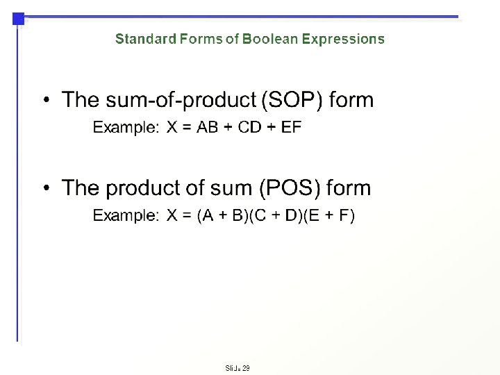
Using Sum-Of-Products • Here, it is not necessarily obvious what kind of logic circuit would satisfy the truth table. • However, a simple method for designing such a circuit is found in a standard form of Boolean expression called the Sum-Of. Products, or SOP, form. • Sum-Of-Products expressions are easy to generate from truth tables.

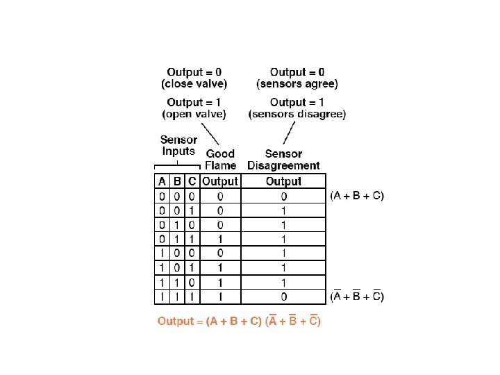
• For instance, in the fourth row down in the truth table for our two-out-of-three logic system, where A=0, B=1, and C=1, the product term would be A’BC, since that term would have a value of 1 if and only if A=0, B=1, and C=1: • Three other rows of the truth table have an output value of 1, so those rows also need Boolean product expressions to represent them:

• Finally, we join these four Boolean product expressions together by addition, to create a single Boolean expression describing the truth table as a whole:

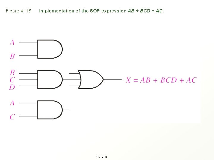
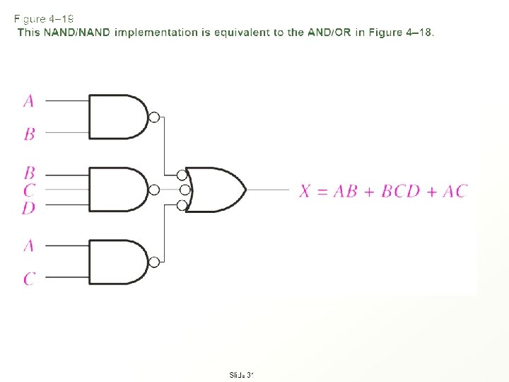
• Now that we have a Boolean Sum-Of-Products expression for the truth table’s function, we can easily design a logic gate or relay logic circuit based on that expression:

• Unfortunately, both of these circuits are quite complex, and could benefit from simplification. Using Boolean algebra techniques, the expression may be significantly simplified:

• As a result of the simplification, we can now build much simpler logic circuits performing the same function, in either gate or relay form:

Using Product-Of-Sums • An alternative to generating a Sum-Of-Products expression to account for all the “high” (1) output conditions in the truth table is to generate a Product. Of-Sums, or POS, expression, to account for all the “low” (0) output conditions instead. • For instance, in the first row of the truth table, where A=0, B=0, and C=0, the sum term would be (A + B + C), since that term would have a value of 0 if and only if A=0, B=0, and C=0:

• Whereas a Sum-Of-Products expression could be implemented in the form of a set of AND gates with their outputs connecting to a single OR gate, a Product-Of-Sums expression can be implemented as a set of OR gates feeding into a single AND gate:

1. Write the Boolean expression of the output Q: 2. Reduce this expression to its simplest form using the rules of Boolean algebra.
·(A + C) = A + B·C")
• Example • Prove (A + B)·(A + C) = A + B·C • • Solution (A + B)·(A + C) = (A + B)·A + (A + B)·C Distributive Law = A·A + B·A + A·C + B·C Distributive Law = A + B·A + A·C + B·C Rule: A·A = A + A·B + A·C + B·C Commutative Law = A + A·C + B·C Rule: A + A·B = A
- Slides: 36