Boolean Algebra Boolean Algbera is a mathematical Model

Boolean Algebra • Boolean Algbera is a mathematical Model for digital logic circuits. – Boolean Algebra is a system <B, V, P> • B={0, 1} is the set of values 1 • V is the set of variables • P={+, • , ΄} is the set of operators (basic functions) defined by the truth tables as follows 2

 nand (not and)")
Boolean operations • • • not or and xor (exclusive or) nand (not and) nor (not or) 4

Not 1 0 0 Note: Some people write x΄ instead of x. The “bubble” (or “bobble”) means “not”. 5

And 0 0 0 1 Notes: Some people write a^b or a&b. The gate is shaped like a “D” as in “an. D”. 6

Or 0 1 1 1 Note: Some people write a b or a|b. 7
 0 1 1 0 8")
Exclusive-or (xor) 0 1 1 0 8

Nand 9

Nor 10
 of Boolean Algebra (A 1) X=0 ���� (A")
Boolean Algebra The axioms (or postulates) of Boolean Algebra (A 1) X=0 ���� (A 1’) X=1 (A 2) If X=0, then X΄=1 (A 2’) If X=1, then X΄=0 (A 3) 0· 0 = 0 (A 3’) 1+1 = 1 (A 4) 1· 1 = 1 (A 4’) 0+0 = 0 (A 5) 0· 1 = 1· 0 = 0 (A 5’) 1+0 = 0+1 = 1 Note We use a prime (΄) to denote an inverter’s function. 11
 X+0 = X (T 2) X+1 =")
Theorems involving a single variable: (T 1) X+0 = X (T 2) X+1 = 1 (T 3) X+X = X (T 4) (X΄)΄ = X (T 5) X+X΄ = 1 (T 1’) X· 1 = X (T 2’) X· 0 = 0 (T 3’) X·X = X (Identities) (Null elements) (Idempotency) (Involution) (T 5’) X·X΄ = 0 (complements) These theorems can be proved to be true. Let us prove T 1: [X=0] 0+0=0 (true, according to A 4) [X=1] 1+0=1 (true, according to A 5) 12
 X+Y = Y+X (T 6’) X·Y")
Theorems involving two or three variables: (T 6) X+Y = Y+X (T 6’) X·Y = Y·X (Commutativity) (T 7) (X+Y)+Z = X+(Y+Z) (T 7’)(X·Y)·Z = X·(Y·Z) (Associativity) (T 8) X·Y+X·Z = X·(Y+Z) (T 8’) (X+Y)·(X+Z) = X+Y·Z (Distributivity) (T 9) X+X·Y = X (T 9’) X·(X+Y) = X (Covering) (T 10) X·Y+X·Y΄ = X (T 10’)(X+Y)·(X+Y΄) = X (Combining) 13
 X·Y+X΄·Z+Y·Z = X·Y+X΄·Z (Consensus) (T 11’)(X+Y)·(X΄+Z)·(Y+Z) = (X+Y)·(X΄+Z) (T 12) (X 1·X")
(T 11) X·Y+X΄·Z+Y·Z = X·Y+X΄·Z (Consensus) (T 11’)(X+Y)·(X΄+Z)·(Y+Z) = (X+Y)·(X΄+Z) (T 12) (X 1·X 2·. . . ·Xn)΄ = X 1΄ +X 2΄+. . . +Xn΄ (T 12’) (X 1+X 2+. . . +Xn)΄ = X 1΄ ·X 2΄·. . . ·Xn΄ ( De. Morgan’s theorems) (T 13) X + X΄ · Y = X + Y (T 13’) X · (X΄ + Y) = X · Y Attention to theorem T 8’ which is not true for integers and reals. T 9 and T 10 are used in the minimisation of logic functions. 14

The most basic representation of a logic function is a truth table. A truth table lists the output of the circuit for every possible input combination. There are 2 n rows in a truth table for an n-variable function. 15
 are sufficient to build any combinational digital")
Gates Three basic gates (AND, OR, NOT) are sufficient to build any combinational digital logic system. 16
 Two more logic functions are obtained by combining NOT with an AND")
Gates (2) Two more logic functions are obtained by combining NOT with an AND or OR function in a single gate. 17
 0 1 1 0 18")
Exclusive-or (xor) 0 1 1 0 18

Equivalent gates according to De. Morgan’s theorem 19

An electrical model a b or a b a and a b a + b b a · b • In a parallel arrangement electricity will flow through if one or other switch is closed. • In a series arrangement both switches must be closed. 20

When SW 1 AND SW 2 are closed. F = SW 1&SW 2 When SW 1 OR SW 2 are closed. F = SW 1+SW 2 21
 ·(p ·q)΄ or (p+q) ·(p ·q)")
Finding the Boolean expression for a circuit (p+q) ·(p ·q)΄ or (p+q) ·(p ·q) 22
 · D)΄ Y")
Finding the Boolean expression for a circuit Y Y = ((A·B+C΄) · D)΄ Y = (A·B+C) · D 23

Finding the Boolean expression for a circuit a f b c 24

Constructing circuits for Boolean expressions To construct a circuit for the expression p'q +q' p q 25

������� Logic diagram ����� Boolean function ������ Y = A'B + AB' A Y B 26

A B C D 27

Simplification of Boolean Functions • General Boolean functions of n variables can be represented by – Boolean expressions – Truth tables showing the function values for all input combinations • Boolean functions can be implemented directly from their expressions, but – Complicated expressions may results in circuits • Using more gates than necessary or • Having longer accumulative gate delay than necessary 28

29


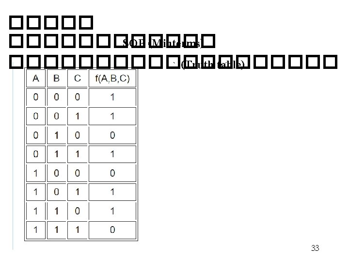
���� �� Truth table X Y Z F • ����� Minterms ������ * 1 0 0 0 0 1 0 0 0 1 0 * 1 0 1 1 0 0 0 0 1 1 0 1 * 1 0 0 1 1 * 1 1 f = x'y'z' + x'yz' + x y'z + x y z f = x'y'z' + x'yz' + x y'z + x y z 31

• But the sum of product of minterms can be further simplified to reduce – the number of product terms and – the number of inputs of the gates – example • f = x'y'z' + x'yz' + xy'z + xyz = x'z'(y'+y) + xz(y'+y) = x'z' + xz But, how do we reach the simplest form systematically? 32
 of n variables -Maxterm boolean expression is developed from the")
• Maxterms (Product-of-Sums) of n variables -Maxterm boolean expression is developed from the 0 s in the output column of the truth table. For each 0 in the output column, an Ored term is developed. -Note that the input variables are inverted and then Ored. A , B , C = 0 A', B', C' = 1 34

���� �� Truth Input Output table C B A F 0 0 0 1 1 0 1 0 1 1 1 0 1 0 0 1 0 * 1 0 1 1 0 1 1 1 0 1 1 1 * • Maxterm Boolean expression : f = (c'+b+a) · (c'+b'+a') 35

Input Output C B A F • จงหา 0 0 0 0 – Minterm Boolean expression 1 0 0 0 – Maxterm Boolean expression 0 1 0 1 0 0 1 0 1 0 1 1 0 1 1 36

Karnaugh Map Simplication • Karnaugh maps ������� Logic • Mapping with minterm expression circuits ������ B'(0) B(1) ������� Input Output A B Y – two variables 00 0 0 1 1 11 0 1 1 1 A'(0) 1 A (1) 1 1 Y = A + B 37

 C(1) A'B'(00) A'B (01) AB (11) AB'(10)")
- three variables and four variables C'(0) C(1) A'B'(00) A'B (01) AB (11) AB'(10) 39

���� �� Truth Output table Input C B A F 0 0 0 1 1 0 0 1 0 1 0 1 1 1 0 1 0 0 0 1 1 1 0 1 1 0 1 1 0 1 1 1 three variables C'(0) C(1) A'B')00( 1 A'B )01( 1 1 AB )11( 1 AB' )10( 1 1 F = C' + A' B + AB' 40

Inputs Output A B C D Y 0 0 1 0 0 0 1 0 0 1 1 0 0 1 0 1 0 0 1 1 0 0 0 1 1 1 0 0 1 0 0 1 0 1 1 1 0 0 0 1 1 1 0 1 1 1 1 four variables C'D' C'D CD CD' A'B')00( 1 A'B )01( 1 AB )11( AB' )10( 1 1 Y = AC + A'C'D' 41

42

43

44

45

46

47

48

Mapping with maxterm expression Input Output A B C F *0 0 0 0 1 1 0 0 1 0 1 0 1 1 1 0 *0 0 0 1 1 1 0 1 *0 0 1 1 1 1 1 1 C C' A+B (0+0) 1 A+B' (0+1) A'+B'(1+1) 1 A'+B (1+0) 1 F = (B + C) · (A'+C) 49

Maxterm CD Minterm AB 0+0 0+1 1+1 1+0 50

 A B C�������")
������� Boolean function ����� Karnaugh maps with minterms ����� (Truth table) A B C������� F ����� 0 0 0 1 1 1 1 0 0 1 1 1 0 1 0 1 X 0 1 0 0 X 1 52
 = S(0, 1, 2, 3,")
���� logic diagram ���� function F(a, b, c, …) = S(0, 1, 2, 3, …) b a 1 0 0 3 2 1 2 3 1 0 6 7 5 4 0 1 3 2 4 5 7 6 12 13 15 14 8 9 11 10 53


Inputs ตำแหนงแถว A B C D 0 0 0 1 1 0 0 0 2 0 1 0 0 3 1 1 1 0 4 0 0 1 0 5 1 0 0 1 6 1 0 1 1 7 0 1 0 0 8 0 1 1 0 9 0 1 10 0 1 11 1 1 0 0 12 1 1 1 0 13 1 1 0 1 14 1 1 15 55
 = S(3, 4, 6, 7) 2 3 1 0 6")
���� F(a, b, c) = S(3, 4, 6, 7) 2 3 1 0 6 7 5 4 b bc a a 1 1 1 c ab c c a 1 1 F = BC + AC' b 56

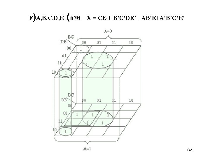
five variables DE BC 00 00 0 01 4 11 12 10 8 A=0 01 11 1 3 5 7 13 15 9 11 10 2 6 14 10 DE BC 00 00 16 01 20 11 28 10 24 A=1 01 11 17 19 21 23 29 31 25 27 10 18 22 30 26 57
 A=0 )0, 2, 5, 7, 13, 15, 17, 18,")
F(A, B, C, D, E) A=0 )0, 2, 5, 7, 13, 15, 17, 18, 19, 21, 23, 29, 31( DE BC 00 01 11 10 1 00 1 1 1 01 1 1 11 10 DE BC 00 00 01 11 10 A=1 01 11 10 1 1 1 1 58
 A=0 )0, 2, 5, 7, 13, 15, 17, 18,")
F(A, B, C, D, E) A=0 )0, 2, 5, 7, 13, 15, 17, 18, 19, 21, 23, 29, 31( DE BC 00 01 11 10 1 00 1 1 1 01 1 1 11 10 DE BC 00 00 01 11 10 A=1 01 11 10 1 1 1 1 F)A, B, C, D, E (= CE + B'C'DE'+ AB'E+A'B' C'E' 59

60

61

Six-Variable K-Map EF CD 00 00 0 01 4 11 12 10 8 EF CD 00 00 32 01 36 11 44 10 40 AB = 00 01 11 1 3 5 7 13 15 9 11 10 2 6 14 10 AB = 10 01 11 33 35 37 39 45 47 41 43 10 34 38 46 42 EF CD 00 00 16 01 20 11 28 10 24 EF CD 00 00 48 01 52 11 60 10 56 AB = 01 01 11 17 19 21 23 29 31 25 27 10 18 22 30 26 AB = 11 01 11 49 51 53 55 61 63 57 59 10 50 54 62 58 63

Six-Variable K-Map EF CD 00 00 01 1 11 10 AB = 00 01 11 10 1 1 AB = 10 01 11 10 EF CD 00 00 01 1 11 10 AB = 01 01 11 10 1 1 1 1 AB = 11 01 11 10 1 1 64

CD = 00 10 11 10 EF 00 01 11 10 AB = 01 AB = 10 65

Combinational circuits ���� Half-Adder ������� Input Output X Y C S 0 0 0 0 0 1 0 1 0 0 1 1 0 1 1 1 S = Sum C = Carry X Y S C 66

Adder Design Example ¨ To design the 4 -bit binary adder, we first design two types of adders: a half adder and a full adder. ¨ A half adder is a combinational circuit that performs the addition of two bits (no carry in). A S • Boolean expressions for S and Co: 1 bit Half Adder B Co A B S Co 0 0 0 1 0 1 1 1 0 0 1 S = AB’+A’B = A Å B Co = AB • Logic diagram: 67

Adder Design Example ¨ Full adder: a combinational circuit that performs the addition of 3 bits (two bits and a carry-in bit). Ai Bi Si C i Ai B i Si Ci+1 0 0 0 1 0 S = A Å BÅ C 0 1 1 0 C = ABC’ +A’BC +AB’C+ABC 1 0 1 = AB(C +C’)+C(AB’ + A’B) 1 1 0 0 1 = AB + C(A + B) 1 1 1 FA Ci Ci+1 68

Full Adder Design Example ¨ Full adder can be realized with two half adders and an OR gate, since Ci+1 can be expressed as: Ai Bi Ci Si Ci+1 69

Binary Decoder • Logic with n input lines and 2 n output lines. • Only one output is a 1 for any given inputs Binary Decoder 2 n outputs 70

• truth table for 2 to 4 decoder: X Y F 0 0 1 0 0 1 0 0 0 1 1 0 0 F 0 1 F 0 2 F F 0 = X'Y' 3 F 1 = X'Y F 2 = XY' F 3 = XY 1 X Y • Note: Each output is a 2 -variable minterm (X'Y', X'Y, XY' or XY) 71

3 -to-8 -Line Decoder 72

73

74
 input lines and n output lines. • The")
Encoder • 2 n (or fewer) input lines and n output lines. • The output lines generate the binary code corresponding to the input value, assuming only one input is high. • An encoder is the reverse function of a decoder 75

8 -to-3 -line Encoder 8 -to-3 Encoder 76

Example: Octal-to-Binary Encoder A 0 = A 1 = A 2 = 77
 to the")
Code Converter Example ¨ Design a circuit that converts a binary-coded-decimal (BCD) to the seven signals required to drive a sevensegment light-emitting diode (LED) display. Assuming the signal 1 illuminates the segment and a logic-0 signal turns off the segment 78

79

Code Converter Example ¨ Derive the Boolean function for each output - e. g. , using the following K-map to derive the Boolean function for output a CD 00 01 11 10 00 1 1 01 0 1 11 0 0 10 1 1 0 0 AB a = A’C + A’BD + A’B’D’+ AB’C’ 80

81

82

83

84

85

86

87
 C(1) A’B’(00) A’B (01) 1 1 1 AB’ (10) 1 AB (11) 88")
C’(0) C(1) A’B’(00) A’B (01) 1 1 1 AB’ (10) 1 AB (11) 88


Karnaugh maps with XOR and XNOR XOR : 90

Truth table : A’B + AB’ = A + B A 0 0 1 1 B 0 1 A’ 1 1 0 0 B’ A’B AB’ A’B + AB’ A + B 1 0 0 0 1 0 1 1 1 0 1 1 1 0 0 0 91

XNOR : 92
’ A 0 0 1")
Truth table : AB + A’B’ = (A + B)’ A 0 0 1 1 B 0 1 A’ 1 1 0 0 B’ AB A’B’ AB + A’B’ (A + B)’ 1 0 1 1 1 0 0 0 0 1 0 0 0 1 0 1 1 93

94

95
- Slides: 95