Axial Load SaintVenants Principle Stress and strain produced



- Slides: 52
Axial Load
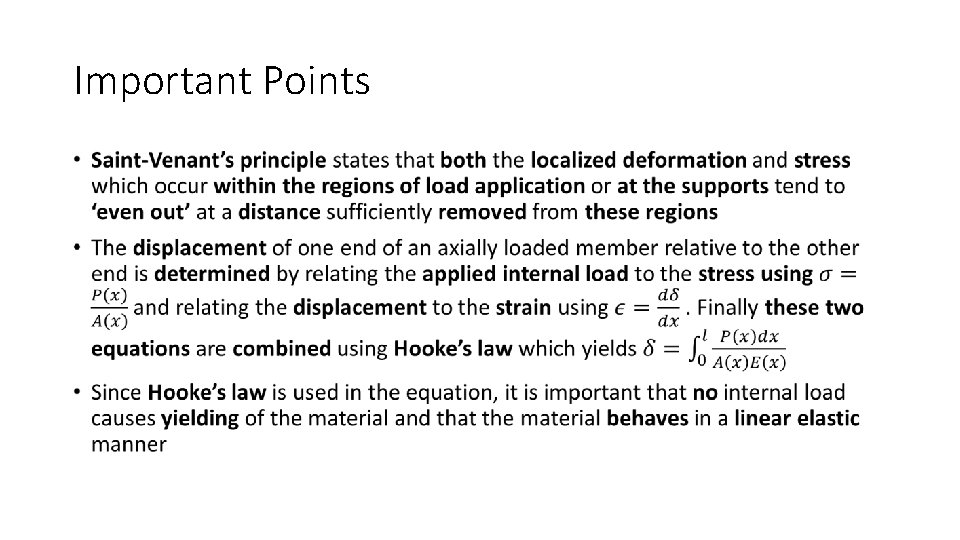
Saint-Venant’s Principle Stress and strain produced at points in a body sufficiently removed from the region of load application will be the same as the stress and strain produced by any applied loadings that have the same statically equivalent resultant and are applied to the body within the same region
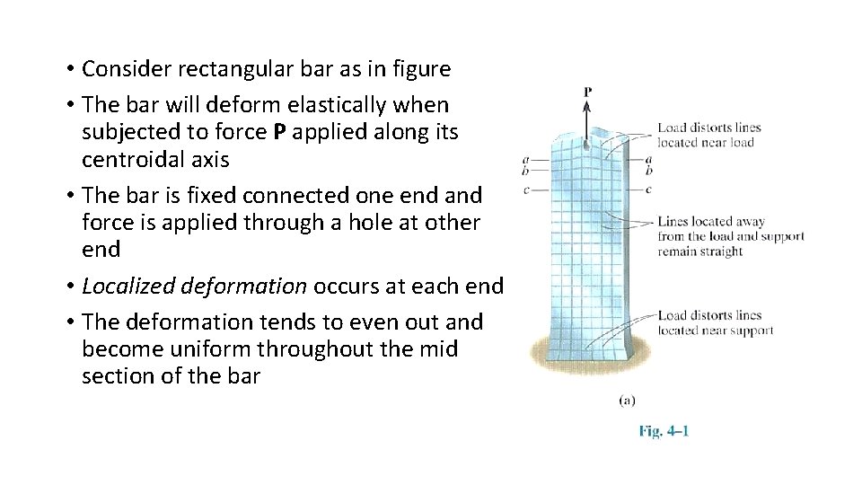
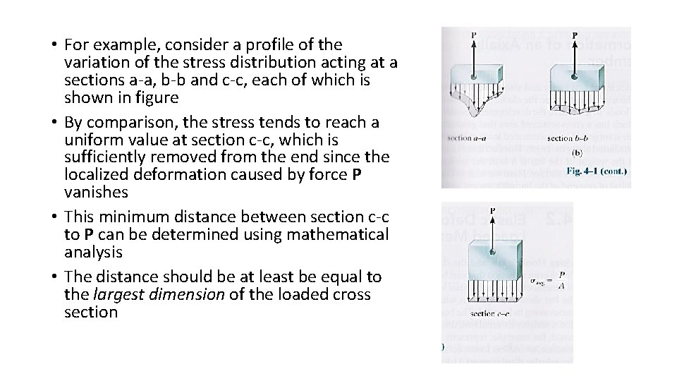
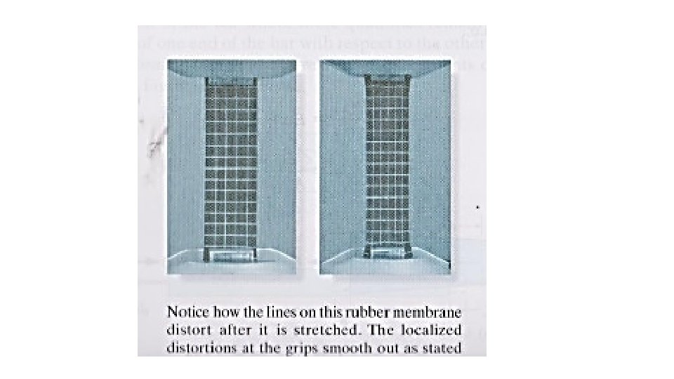
• Consider rectangular bar as in figure • The bar will deform elastically when subjected to force P applied along its centroidal axis • The bar is fixed connected one end and force is applied through a hole at other end • Localized deformation occurs at each end • The deformation tends to even out and become uniform throughout the mid section of the bar
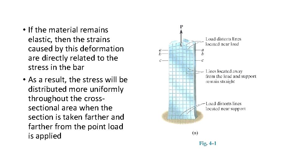
• If the material remains elastic, then the strains caused by this deformation are directly related to the stress in the bar • As a result, the stress will be distributed more uniformly throughout the crosssectional area when the section is taken farther and farther from the point load is applied
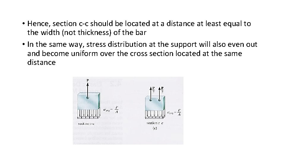
• For example, consider a profile of the variation of the stress distribution acting at a sections a-a, b-b and c-c, each of which is shown in figure • By comparison, the stress tends to reach a uniform value at section c-c, which is sufficiently removed from the end since the localized deformation caused by force P vanishes • This minimum distance between section c-c to P can be determined using mathematical analysis • The distance should be at least be equal to the largest dimension of the loaded cross section
• Hence, section c-c should be located at a distance at least equal to the width (not thickness) of the bar • In the same way, stress distribution at the support will also even out and become uniform over the cross section located at the same distance
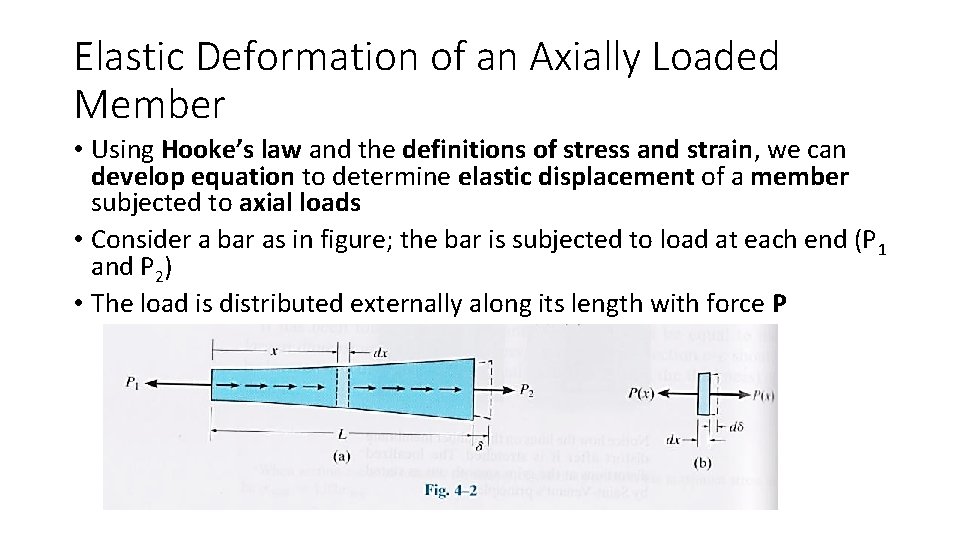
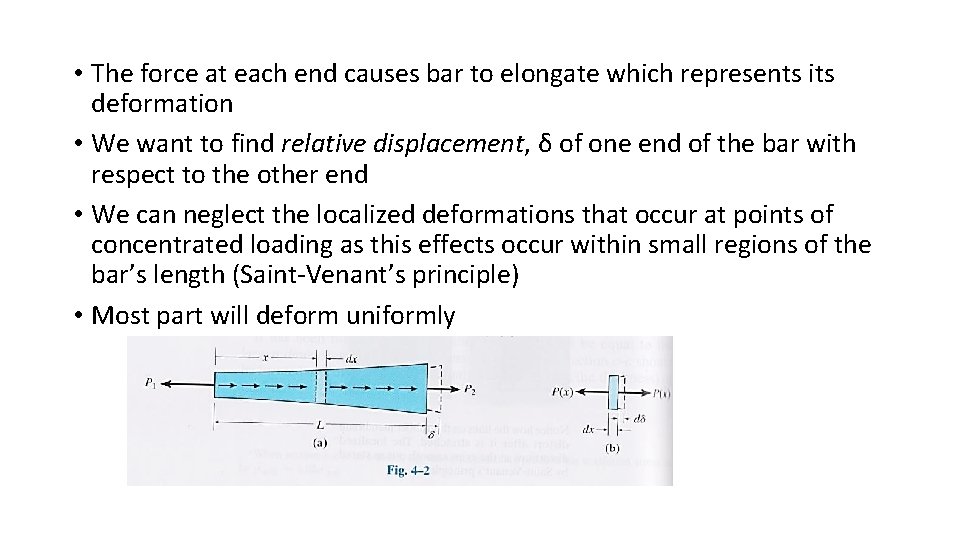
Elastic Deformation of an Axially Loaded Member • Using Hooke’s law and the definitions of stress and strain, we can develop equation to determine elastic displacement of a member subjected to axial loads • Consider a bar as in figure; the bar is subjected to load at each end (P 1 and P 2) • The load is distributed externally along its length with force P
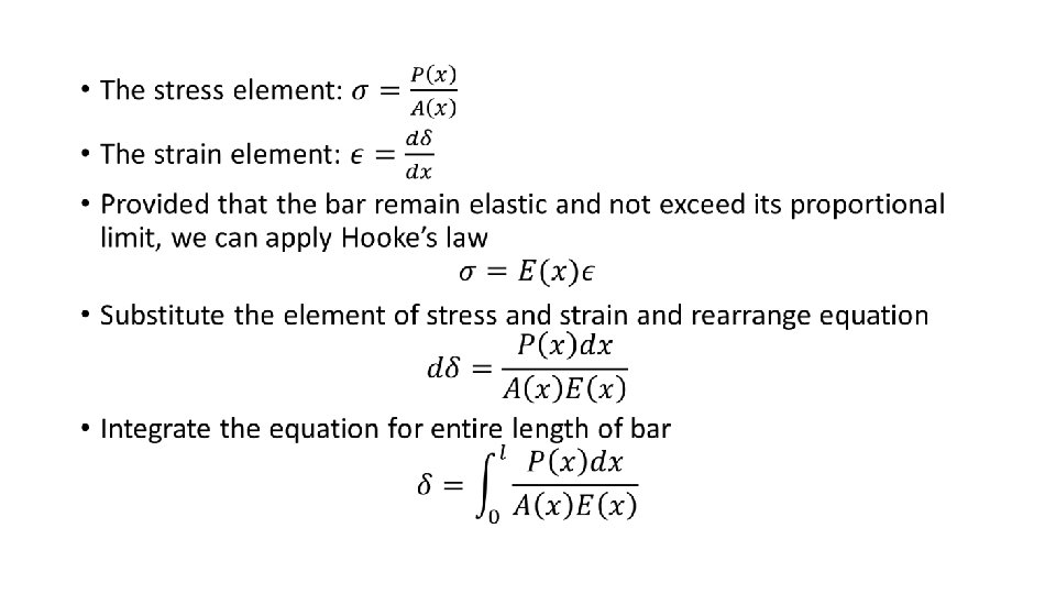
• The force at each end causes bar to elongate which represents its deformation • We want to find relative displacement, δ of one end of the bar with respect to the other end • We can neglect the localized deformations that occur at points of concentrated loading as this effects occur within small regions of the bar’s length (Saint-Venant’s principle) • Most part will deform uniformly
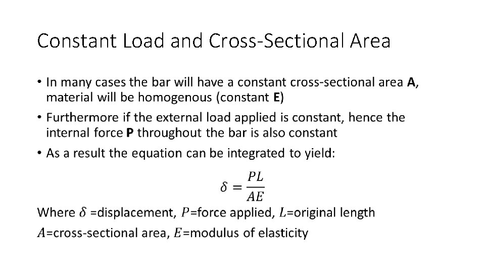
Constant Load and Cross-Sectional Area •
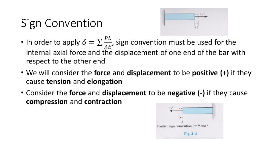
Sign Convention •
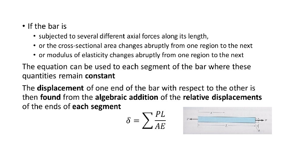
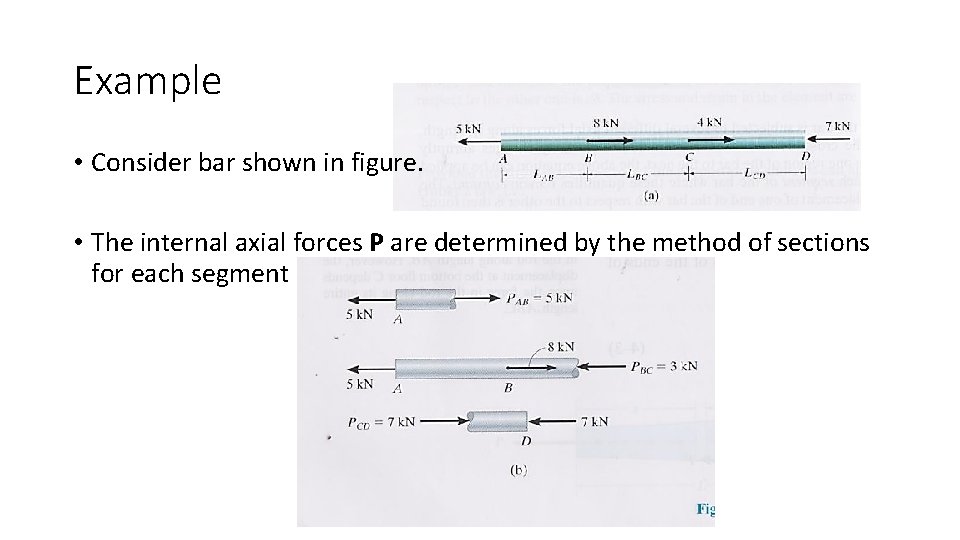
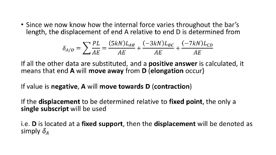
Example • Consider bar shown in figure. • The internal axial forces P are determined by the method of sections for each segment
Important Points •
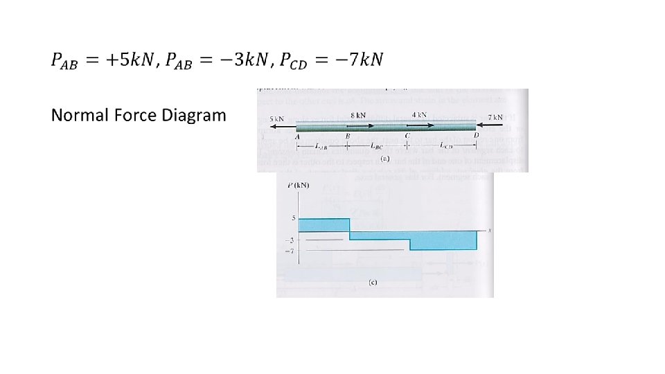
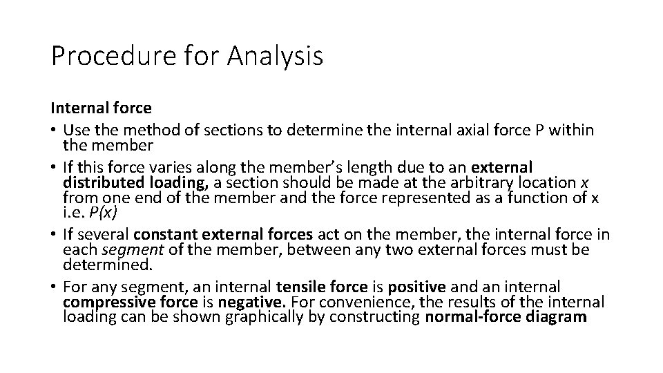
Procedure for Analysis Internal force • Use the method of sections to determine the internal axial force P within the member • If this force varies along the member’s length due to an external distributed loading, a section should be made at the arbitrary location x from one end of the member and the force represented as a function of x i. e. P(x) • If several constant external forces act on the member, the internal force in each segment of the member, between any two external forces must be determined. • For any segment, an internal tensile force is positive and an internal compressive force is negative. For convenience, the results of the internal loading can be shown graphically by constructing normal-force diagram
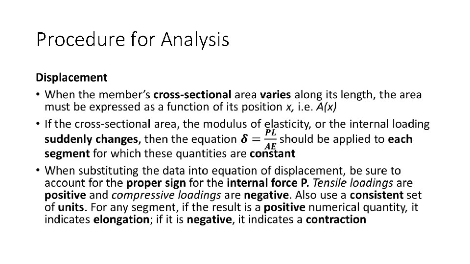
Procedure for Analysis •
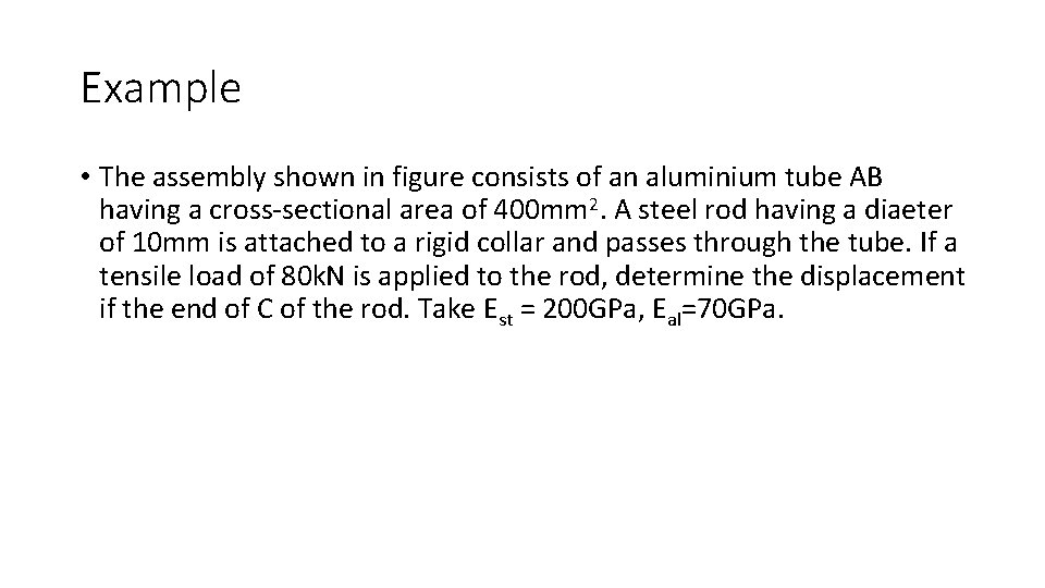
Example • The assembly shown in figure consists of an aluminium tube AB having a cross-sectional area of 400 mm 2. A steel rod having a diaeter of 10 mm is attached to a rigid collar and passes through the tube. If a tensile load of 80 k. N is applied to the rod, determine the displacement if the end of C of the rod. Take Est = 200 GPa, Eal=70 GPa.
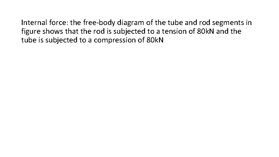
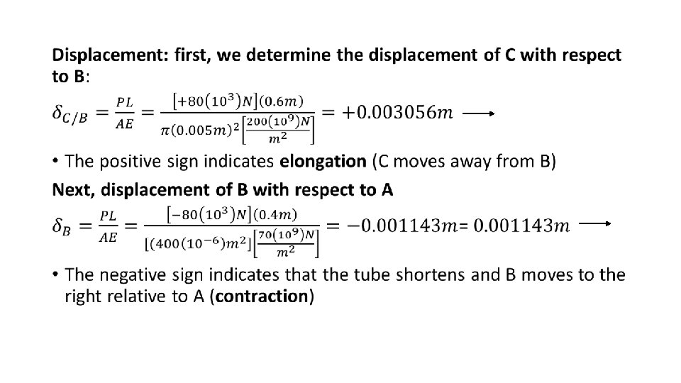
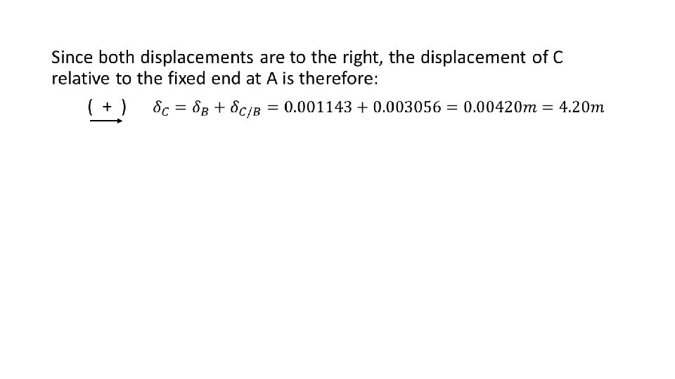
Internal force: the free-body diagram of the tube and rod segments in figure shows that the rod is subjected to a tension of 80 k. N and the tube is subjected to a compression of 80 k. N
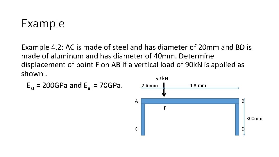
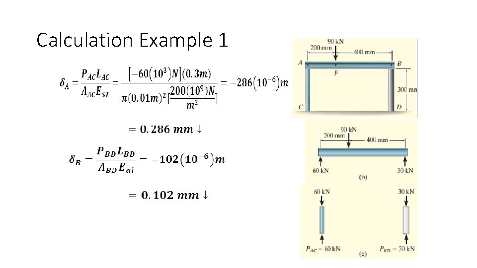
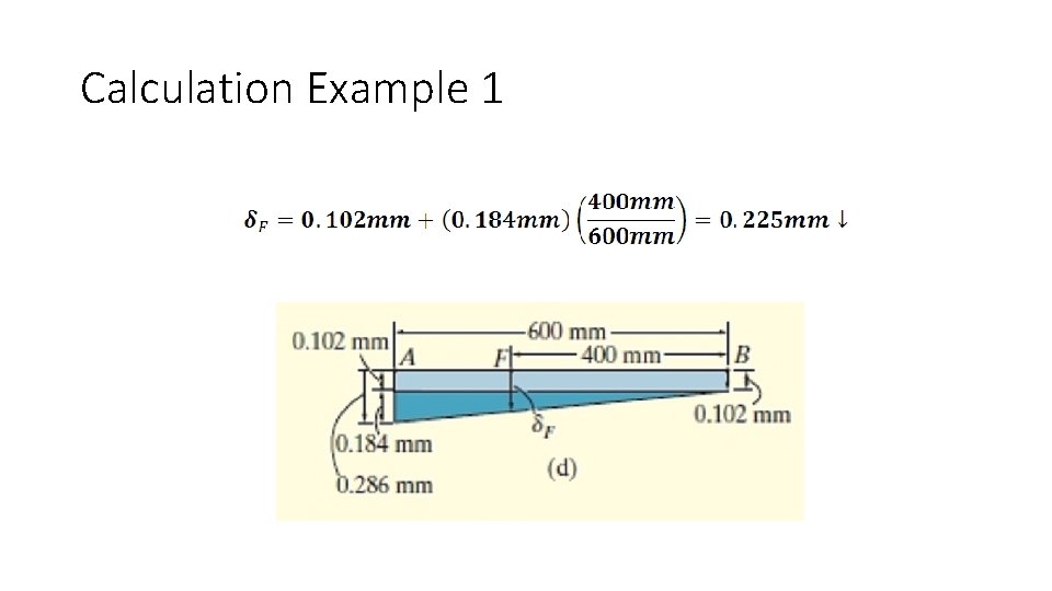
Example 4. 2: AC is made of steel and has diameter of 20 mm and BD is made of aluminum and has diameter of 40 mm. Determine displacement of point F on AB if a vertical load of 90 k. N is applied as shown. 90 k. N 400 mm 200 mm Est = 200 GPa and Eal = 70 GPa. A B F 300 mm C D
Calculation Example 1
Calculation Example 1
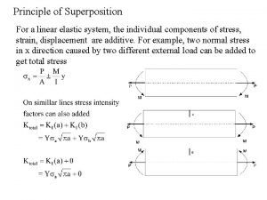
Principle of Superposition • States that the resultant stress or displacement at the point can be determined by algebraically summing the stress or displacement caused by each load component applied separately to the member • Used to determine the stress or displacement at a point in a member when the member is subjected to a complicated loading
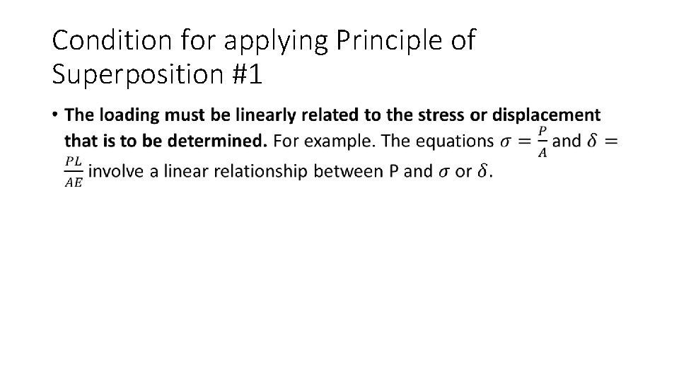
Condition for applying Principle of Superposition #1 •
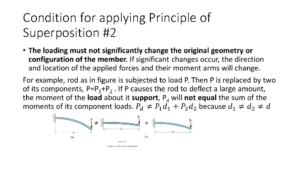
Condition for applying Principle of Superposition #2 •
Principle of Superposition • It can be used to simplify problems having complicated loadings. This is done by dividing the loading into components, then algebraically adding the results. • It is applicable provided the material obeys Hooke’s Law and the deformation is small. • Bodies that are considered will be such that the loading will produce deformations that are so small that the change in position and direction of the loading will be insignificant and can be neglected
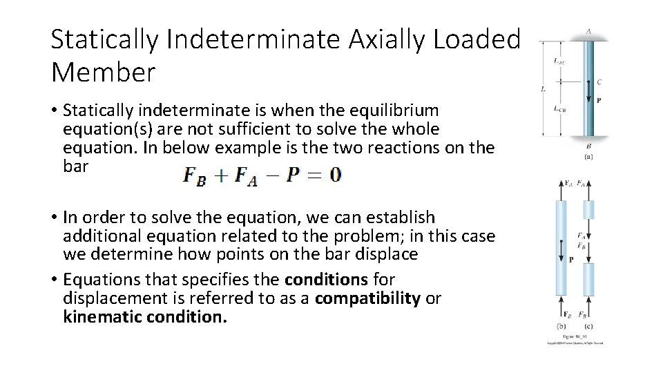
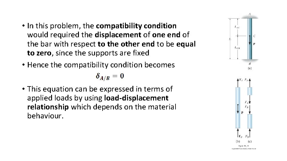
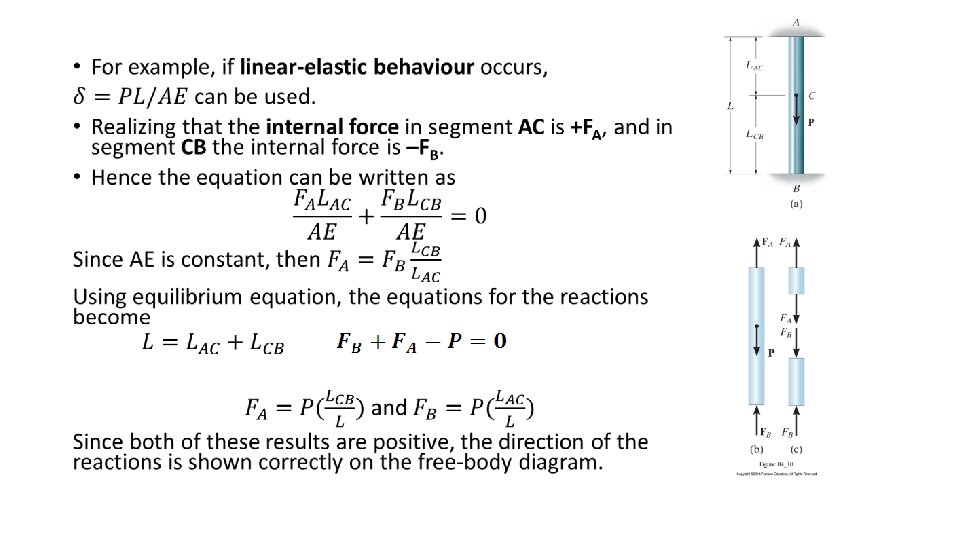
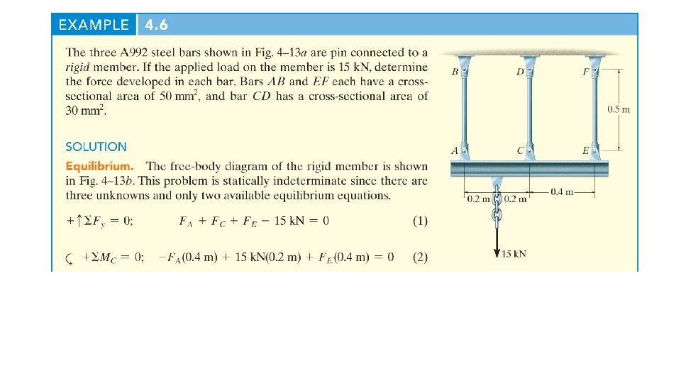
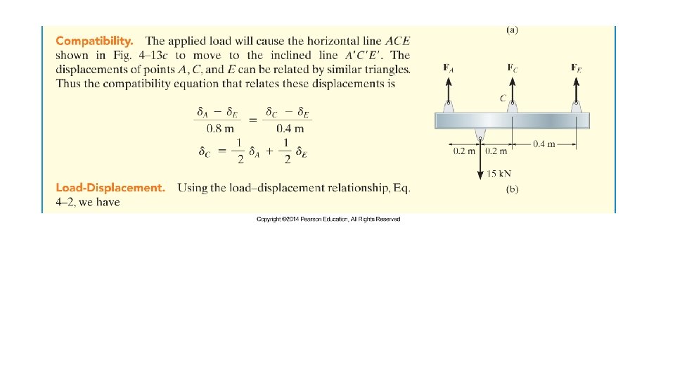
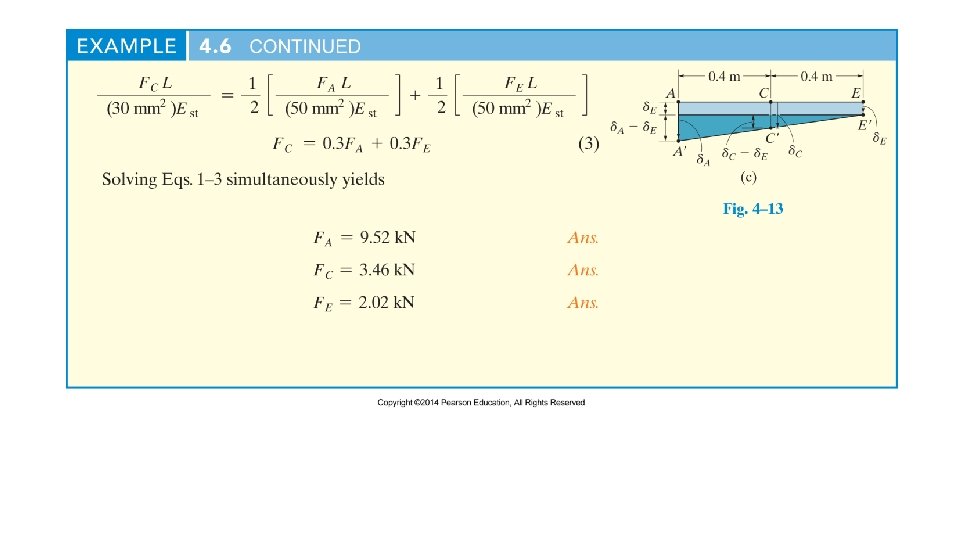
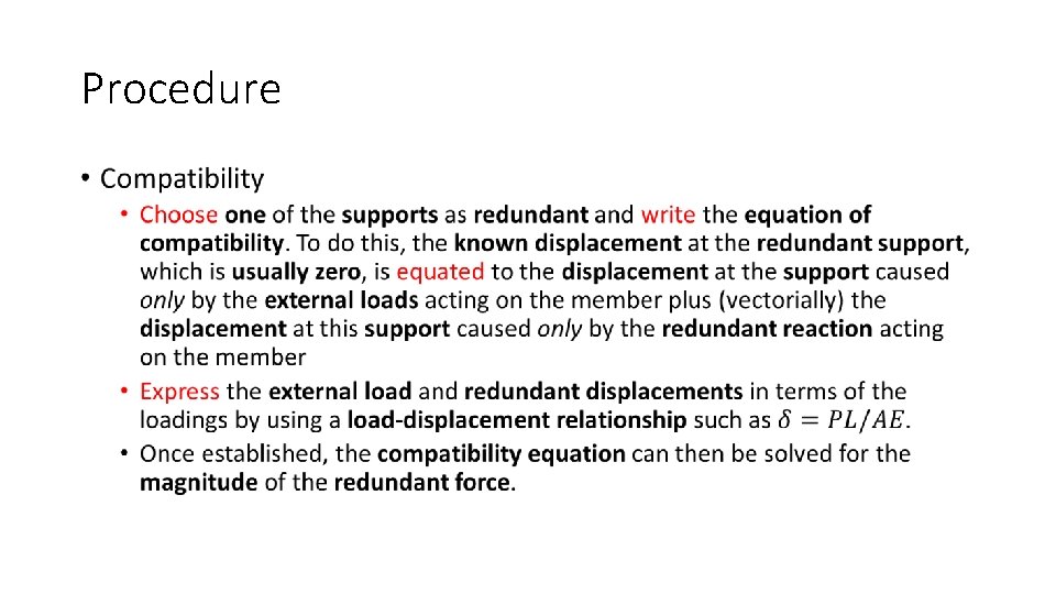
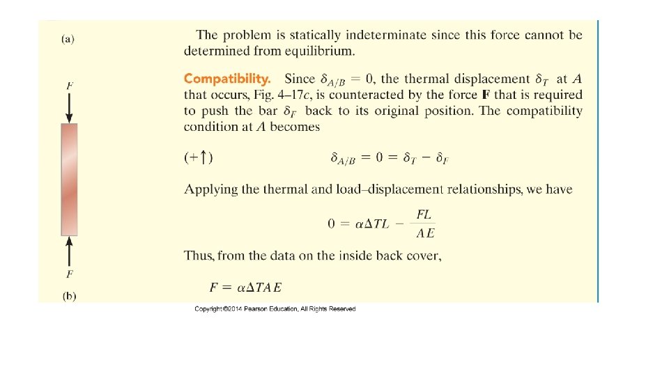
Statically Indeterminate Axially Loaded Member • Statically indeterminate is when the equilibrium equation(s) are not sufficient to solve the whole equation. In below example is the two reactions on the bar • In order to solve the equation, we can establish additional equation related to the problem; in this case we determine how points on the bar displace • Equations that specifies the conditions for displacement is referred to as a compatibility or kinematic condition.
• In this problem, the compatibility condition would required the displacement of one end of the bar with respect to the other end to be equal to zero, since the supports are fixed • Hence the compatibility condition becomes • This equation can be expressed in terms of applied loads by using load-displacement relationship which depends on the material behaviour.
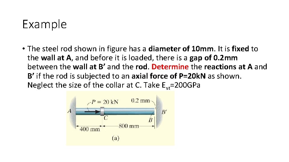
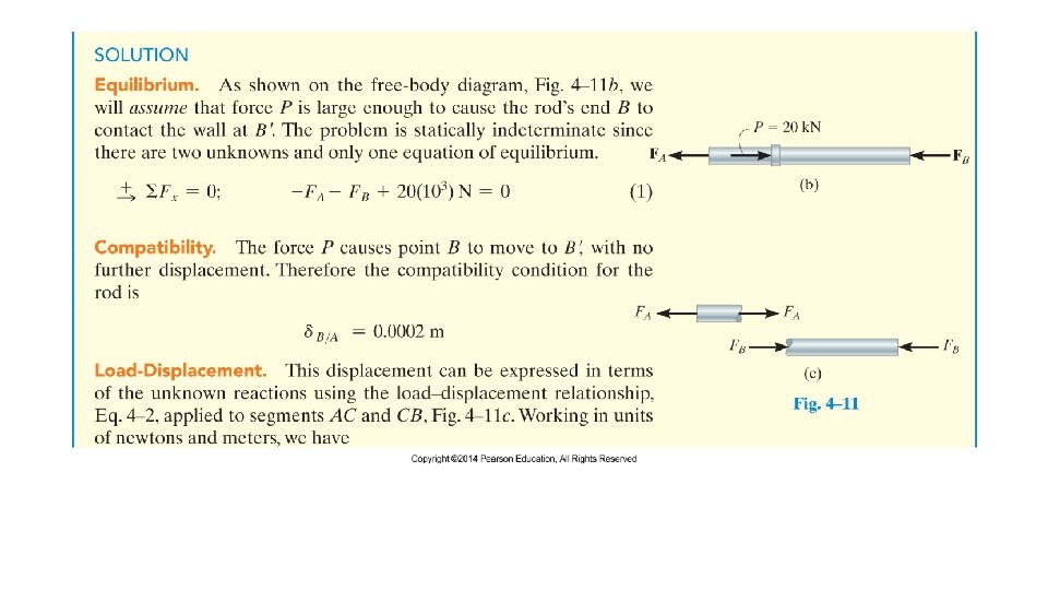
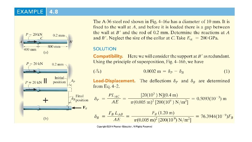
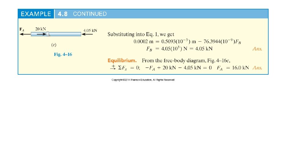
Example • The steel rod shown in figure has a diameter of 10 mm. It is fixed to the wall at A, and before it is loaded, there is a gap of 0. 2 mm between the wall at B’ and the rod. Determine the reactions at A and B’ if the rod is subjected to an axial force of P=20 k. N as shown. Neglect the size of the collar at C. Take Est=200 GPa
Force Method Analysis • It is also possible to solve statically indeterminate problem by writing the compatibility equation using the superposition of the forces acting on the free body diagram.
Procedure •
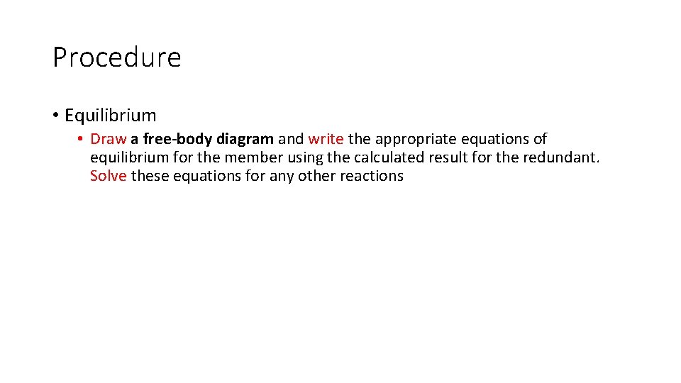
Procedure • Equilibrium • Draw a free-body diagram and write the appropriate equations of equilibrium for the member using the calculated result for the redundant. Solve these equations for any other reactions
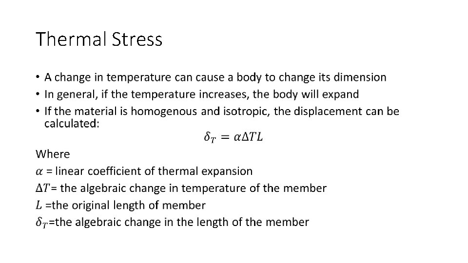
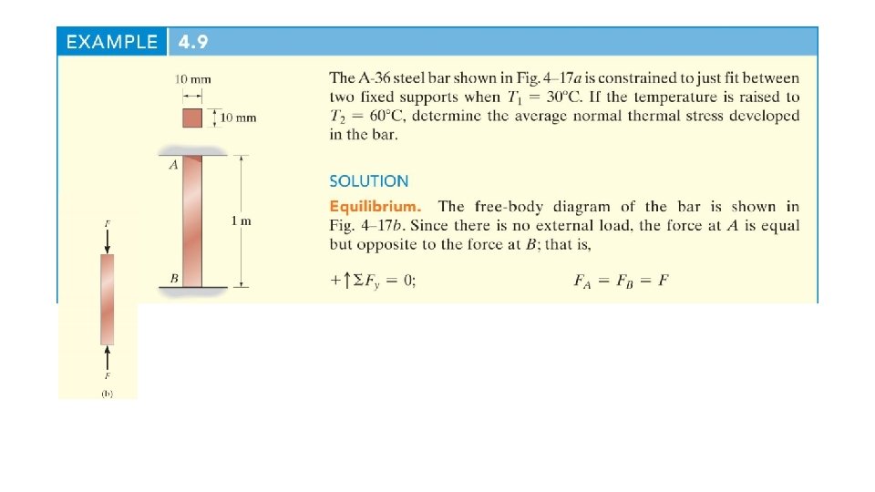
Thermal Stress •