TOPICS Topic cover Stress and strain Introduction to


 • Elastic materials always spring back into shape when released.")


 • If we conduct an experiment and measure x for")


- Slides: 40
TOPICS • Topic cover – Stress and strain • • • Introduction to stress and strain, stress strain diagram Elasticity and plasticity and Hooke’s law Shear Stress and Shear strain Load and stress limit Axial force and deflection of body – Torsion • Introduction, round bar torsion, non-uniform torsion. • Relation between Young’s Modulus E, and G • Power transmission on round bar Visit for more Learning Resources
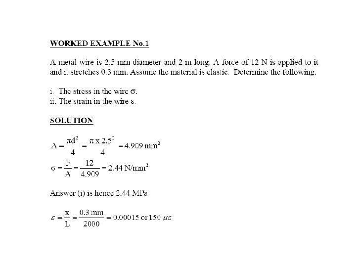
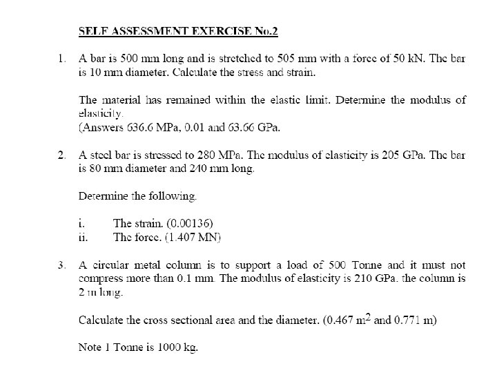
DIRECT STRESS Ø Stress and strain When a force is applied to an elastic body, the body deforms. The way in which the body deforms depends upon the type of force applied to it. Compression force makes the body shorter. A tensile force makes the body longer
Tensile and compressive forces are called DIRECT FORCES Stress is the force per unit area upon which it acts. …. . Unit is Pascal (Pa) or ( Simbol – Sigma) Note: Most of engineering fields used k. Pa, MPa, GPa.
DIRECT STRAIN , In each case, a force F produces a deformation x. In engineering, we usually change this force into stress and the deformation into strain and we define these as follows: Strain is the deformation per unit of the original length. The symbol called EPSILON Strain has no unit’s since it is a ratio of length to length. Most engineering materials do not stretch very mush before they become damages, so strain values are very small figures. It is quite normal to change small numbers in to the exponent for 10 -6( micro strain).
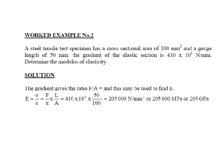
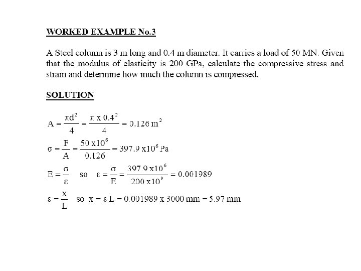
MODULUS OF ELASTICITY (E) • Elastic materials always spring back into shape when released. They also obey HOOKE’s LAW. • This is the law of spring which states that deformation is directly proportional to the force. F/x = stiffness = k. N/m • The stiffness is different for the different material and different sizes of the material. We may eliminate the size by using stress and strain instead of force and deformation: • If F and x is refer to the direct stress and strain , then hence and
• The stiffness is now in terms of stress and strain only and this constant is called the MODULUS of ELASTICITY (E) • A graph of stress against strain will be straight line with gradient of E. The units of E are the same as the unit of stress. ULTIMATE TENSILE STRESS • If a material is stretched until it breaks, the tensile stress has reached the absolute limit and this stress level is called the ultimate tensile stress.
STRESS STRAIN DIAGRAM
STRESS STRAIN DIAGRAM Elastic behaviour The curve is straight line trough out most of the region Stress is proportional with strain Material to be linearly elastic Proportional limit The upper limit to linear line The material still respond elastically The curve tend to bend and flatten out Elastic limit Upon reaching this point, if load is remove, the specimen still return to original shape
STRESS STRAIN DIAGRAM Yielding A Slight increase in stress above the elastic limit will result in breakdown of the material and cause it to deform permanently. This behaviour is called yielding The stress that cause = YIELD STRESS@YIELD POINT Plastic deformation Once yield point is reached, the specimen will elongate (Strain) without any increase in load Material in this state = perfectly plastic
STRESS STRAIN DIAGRAM • STRAIN HARDENING – When yielding has ended, further load applied, resulting in a curve that rises continuously – Become flat when reached ULTIMATE STRESS – The rise in the curve = STRAIN HARDENING – While specimen is elongating, its cross sectional will decrease – The decrease is fairly uniform • NECKING – At the ultimate stress, the cross sectional area begins its localised region of specimen – it is caused by slip planes formed within material – Actual strain produced by shear strain – As a result, “neck” tend to form – Smaller area can only carry lesser load, hence curve donward – Specimen break at FRACTURE STRESS
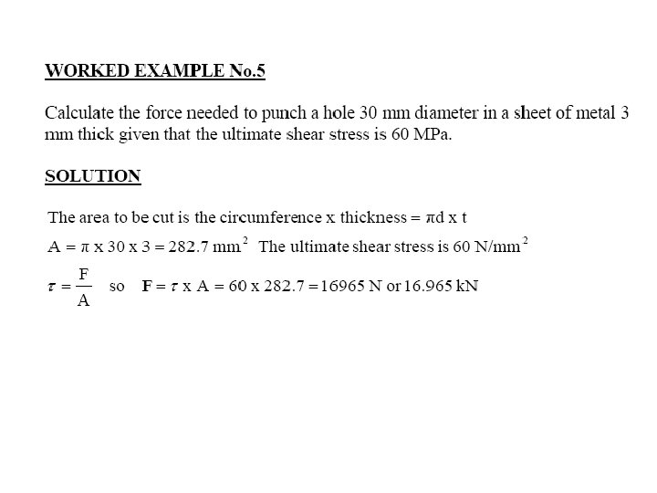
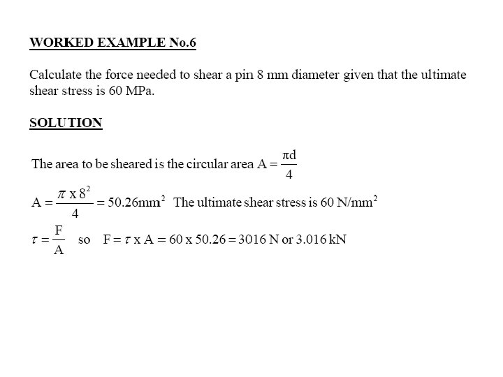
SHEAR STRESS • Shear force is a force applied sideways on the material (transversely loaded). When a pair of shears cut a material When a material is punched When a beam has a transverse load
ØShear stress is the force per unit area carrying the load. This means the cross sectional area of the material being cut, the beam and pin. • Shear stress, and symbol is called Tau ØThe sign convention for shear force and stress is based on how it shears the materials as shown below.
SHEAR STRAIN The force causes the material to deform as shown. The shear strain is defined as the ratio of the distance deformed to the height . Since this is a very small angle , Shear strain ( symbol called Gamma) we can say that :
MODULUS OF RIGIDITY (G) • If we conduct an experiment and measure x for various values of F, we would find that if the material is elastic, it behave like spring and so long as we do not damage the material by using too big force, the graph of F and x is straight line as shown. The gradient of the graph is constant so and this is the spring stiffness of the block in N/m. • If we divide F by area A and x by the height L, the relationship is still a constant and we get
• If we divide F by area A and x by the height L, the relationship is still a constant and we get Where then This constant will have a special value for each elastic material and is called the Modulus of Rigidity (G).
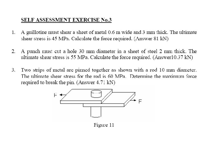
ULTIMATE SHEAR STRESS If a material is sheared beyond a certain limit and it becomes permanently distorted and does not spring all the way back to its original shape, the elastic limit has been exceeded. If the material stressed to the limit so that it parts into two, the ultimate limit has been reached. The ultimate shear stress has symbol and this value is used to calculate the force needed by shears and punches.
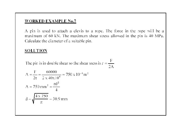
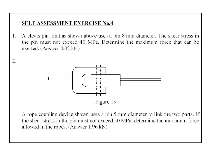
DOUBLE SHEAR Consider a pin joint with a support on both ends as shown. This is called CLEVIS and CLEVIS PIN By balance of force, the force in the two supports is F/2 each The area sheared is twice the cross section of the pin So it takes twice as much force to break the pin as for a case of single shear Double shear arrangements doubles the maximum force allowed in the pin
LOAD AND STRESS LIMIT DESIGN CONSIDERATION Will help engineers with their important task in Designing structural/machine that is SAFE and ECONOMICALLY perform for a specified function DETERMINATION OF ULTIMATE STRENGTH An important element to be considered by a designer is how the material that has been selected will behave under a load This is determined by performing specific test (e. g. Tensile test) ULTIMATE FORCE (PU)= The largest force that may be applied to the specimen is reached, and the specimen either breaks or begins to carry less load ULTIMATE NORMAL STRESS ( U) = ULTIMATE FORCE(PU) /AREA
ALLOWABLE LOAD / ALLOWABLE STRESS Max load that a structural member/machine component will be allowed to carry under normal conditions of utilisation is considerably smaller than the ultimate load This smaller load = Allowable load / Working load / Design load Only a fraction of ultimate load capacity of the member is utilised when allowable load is applied The remaining portion of the load-carrying capacity of the member is kept in reserve to assure its safe performance The ratio of the ultimate load/allowable load is used to define FACTOR OF SAFETY = ULTIMATE LOAD/ALLOWABLE LOAD @ FACTOR OF SAFETY = ULTIMATE STRESS/ALLOWABLE STRESS
SELECTION OF F. S. 1. Variations that may occur in the properties of the member under considerations 2. The number of loading that may be expected during the life of the structural/machine 3. The type of loading that are planned for in the design, or that may occur in the future 4. The type of failure that may occur 5. Uncertainty due to the methods of analysis 6. Deterioration that may occur in the future because of poor maintenance / because of unpreventable natural causes 7. The importance of a given member to the integrity of the whole structure
WORKED EXAMPLE 8 0. 6 m
SOLUTION
SOLUTION
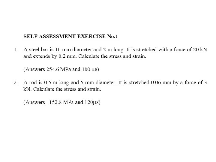
SELF ASSESSMENT NO. 5
AXIAL FORCE & DEFLECTION OF BODY Deformations of members under axial loading If the resulting axial stress does not exceed the proportional limit of the material, Hooke’s Law may be applied Then deformation (x / ) can be written as
WORKED EXAMPLE 9 0. 4 m
WORKED EXAMPLE 9
WORKED EXAMPLE 9
SELF ASSESSMENT NO. 6 For more detail contact us