AIR NAVIGATION Air navigation introduction Pilotage and dead









- Slides: 60
AIR NAVIGATION
• • • Air navigation introduction Pilotage and dead reckoning Maps and charts Mission planning Dead reckoning with basic instruments Lines of position, bearing and fix Map reading Time Use of flight computer
Importance things before getting start • • • LATITUDE AND LONGITUDE TIME ZONES MEASUREMENT OF DIRECTION EFFECT OF WIND THE WIND TRIANGLE OR VECTOR ANALYSIS VARIATION ISOGONIC AND AGONIC LINE DEVIATION TRUE AND MAGNETIC VALUES
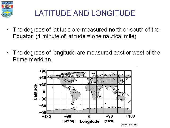
LATITUDE AND LONGITUDE • The degrees of latitude are measured north or south of the Equator. (1 minute of latitude = one nautical mile) • The degrees of longitude are measured east or west of the Prime meridian.
TIME ZONES • The meridians are also useful for designating time zones. • A day is defined as the time required for the Earth to make one complete rotation of 360º. • Since the day is divided into 24 hours, the Earth revolves at the rate of 15º an hour. • The standard practice is to establish a time zone for each 15º of longitude. This makes a difference of exactly 1 hour between each zone.
TIME ZONES • Noon is the time when the Sun is directly above a meridian; to the west of that meridian is morning, to the east is afternoon.
TIME • The time of the day – Zulu time – Local time • An elapsed interval
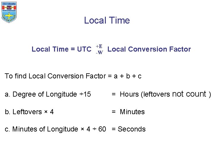
Local Time = UTC +E -W Local Conversion Factor To find Local Conversion Factor = a + b + c a. Degree of Longitude ÷ 15 = Hours (leftovers not count ) b. Leftovers × 4 = Minutes c. Minutes of Longitude × 4 ÷ 60 = Seconds
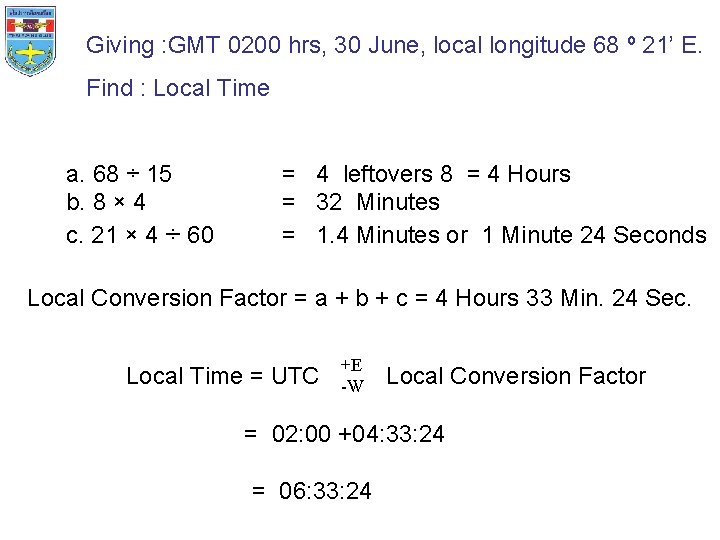
Giving : GMT 0200 hrs, 30 June, local longitude 68 º 21’ E. Find : Local Time a. 68 ÷ 15 b. 8 × 4 c. 21 × 4 ÷ 60 = 4 leftovers 8 = 4 Hours = 32 Minutes = 1. 4 Minutes or 1 Minute 24 Seconds Local Conversion Factor = a + b + c = 4 Hours 33 Min. 24 Sec. +E Local Time = UTC Local Conversion Factor -W = 02: 00 +04: 33: 24 = 06: 33: 24
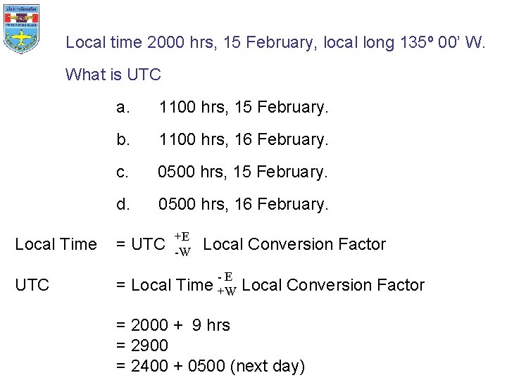
Local time 2000 hrs, 15 February, local long 135º 00’ W. What is UTC a. 1100 hrs, 15 February. b. 1100 hrs, 16 February. c. 0500 hrs, 15 February. d. 0500 hrs, 16 February. +E Local Time = UTC Local Conversion Factor -W UTC -E = Local Time Local Conversion Factor +W = 2000 + 9 hrs = 2900 = 2400 + 0500 (next day)
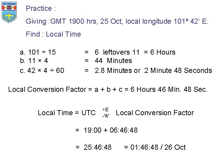
Practice : Giving : GMT 1900 hrs, 25 Oct, local longitude 101º 42’ E. Find : Local Time a. 101 ÷ 15 b. 11 × 4 c. 42 × 4 ÷ 60 = 6 leftovers 11 = 6 Hours = 44 Minutes = 2. 8 Minutes or 2 Minute 48 Seconds Local Conversion Factor = a + b + c = 6 Hours 46 Min. 48 Sec. +E Local Time = UTC Local Conversion Factor -W = 19: 00 + 06: 48 = 25: 46: 48 = 01: 46: 48 / 26 Oct
MEASUREMENT OF DIRECTION • By using the meridians, direction from one point to another can be measured in degrees, in a clockwise direction from true north. • To indicate a course to be followed in flight, draw a line on the chart from the point of departure to the destination and measure the angle which this line forms with a meridian.
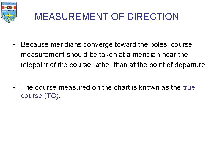
MEASUREMENT OF DIRECTION • Because meridians converge toward the poles, course measurement should be taken at a meridian near the midpoint of the course rather than at the point of departure. • The course measured on the chart is known as the true course (TC).
MEASUREMENT OF DIRECTION • As shown, the direction from A to B would be a true course of 065º , whereas the return trip (called the reciprocal) would be a true course of 245º
EFFECT OF WIND • The airplane will fly faster with a tailwind or slower with a headwind, or to drift right or left with a crosswind.
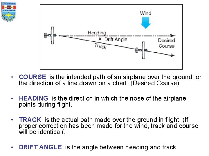
• COURSE is the intended path of an airplane over the ground; or the direction of a line drawn on a chart. (Desired Course) • HEADING is the direction in which the nose of the airplane points during flight. • TRACK is the actual path made over the ground in flight. (If proper correction has been made for the wind, track and course will be identical(. • DRIFT ANGLE is the angle between heading and track.
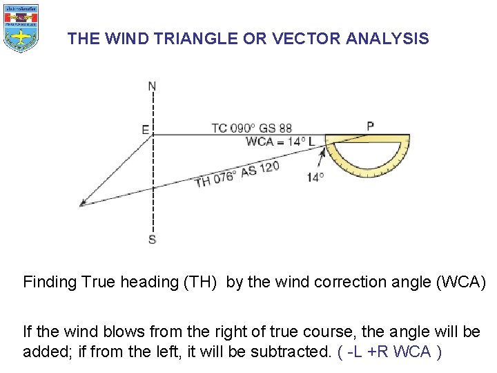
• WIND CORRECTION ANGLE is correction applied to the course to establish a heading so that track will coincide with course. • True course correct for the wind = True heading TC – WCA = TH
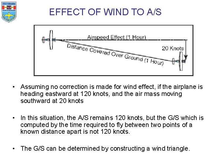
EFFECT OF WIND TO A/S • Assuming no correction is made for wind effect, if the airplane is heading eastward at 120 knots, and the air mass moving southward at 20 knots • In this situation, the A/S remains 120 knots, but the G/S which is computed by the time required to fly between two points of a known distance apart is not 120 knots. • The G/S can be determined by constructing a wind triangle.
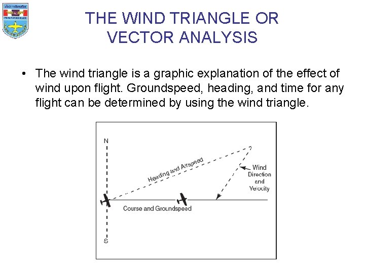
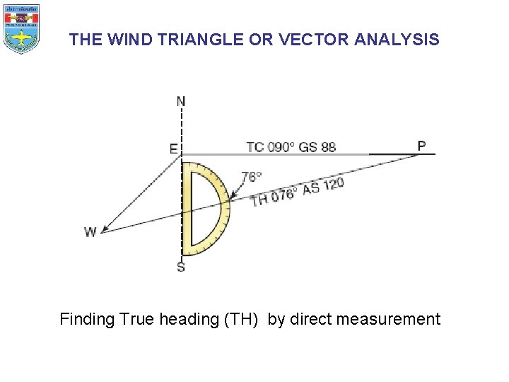
THE WIND TRIANGLE OR VECTOR ANALYSIS • The wind triangle is a graphic explanation of the effect of wind upon flight. Groundspeed, heading, and time for any flight can be determined by using the wind triangle.
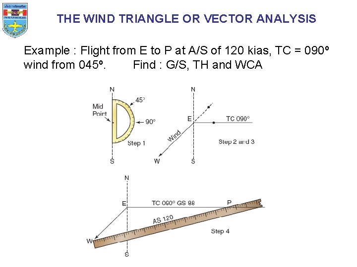
THE WIND TRIANGLE OR VECTOR ANALYSIS Example : Flight from E to P at A/S of 120 kias, TC = 090º wind from 045º. Find : G/S, TH and WCA
THE WIND TRIANGLE OR VECTOR ANALYSIS Finding True heading (TH) by direct measurement
THE WIND TRIANGLE OR VECTOR ANALYSIS Finding True heading (TH) by the wind correction angle (WCA) If the wind blows from the right of true course, the angle will be added; if from the left, it will be subtracted. ( -L +R WCA )
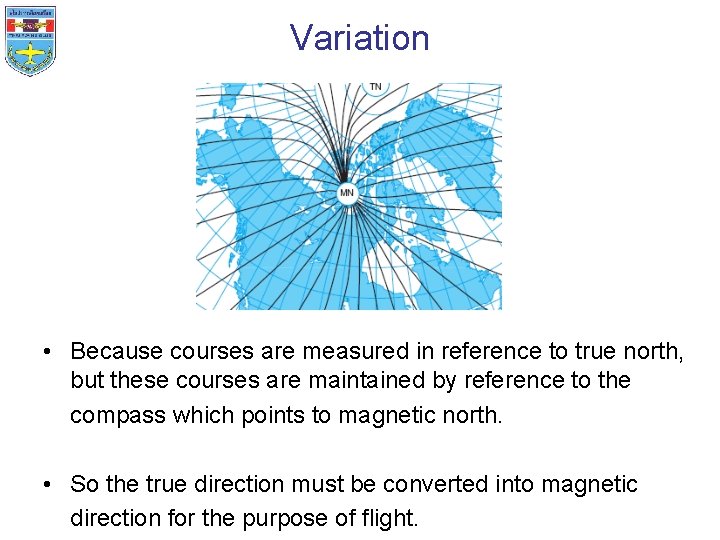
Variation • Because courses are measured in reference to true north, but these courses are maintained by reference to the compass which points to magnetic north. • So the true direction must be converted into magnetic direction for the purpose of flight.
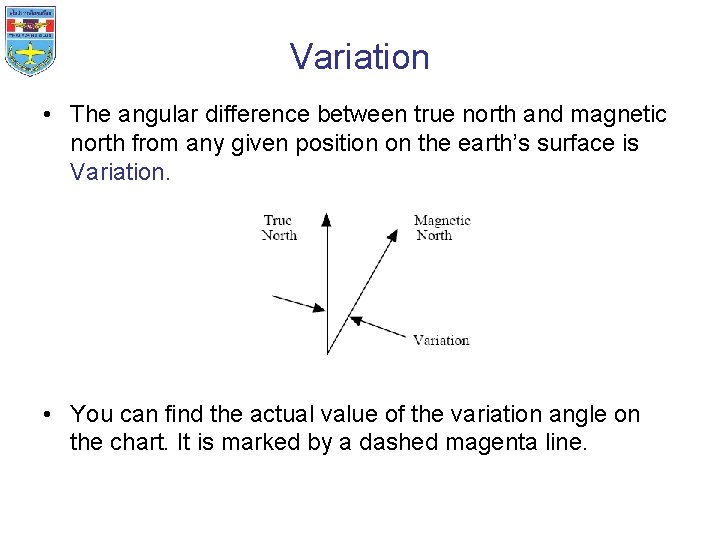
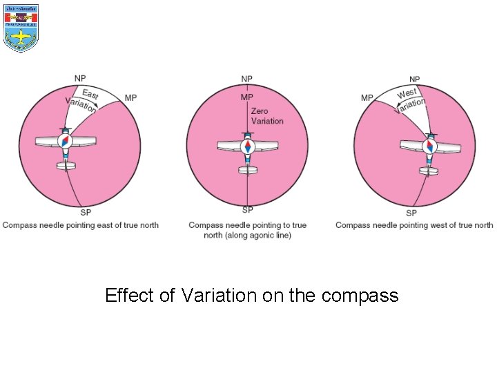
Variation • The angular difference between true north and magnetic north from any given position on the earth’s surface is Variation. • You can find the actual value of the variation angle on the chart. It is marked by a dashed magenta line.
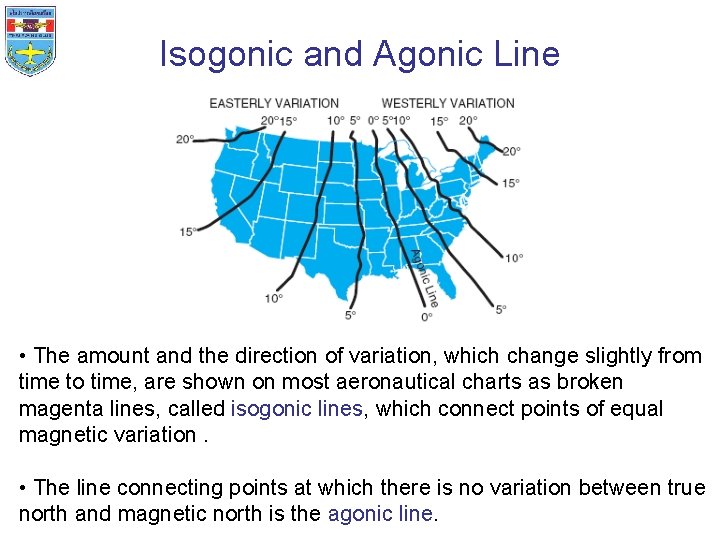
Isogonic and Agonic Line • The amount and the direction of variation, which change slightly from time to time, are shown on most aeronautical charts as broken magenta lines, called isogonic lines, which connect points of equal magnetic variation. • The line connecting points at which there is no variation between true north and magnetic north is the agonic line.
Variation • To convert true course or heading to magnetic course or heading, note the variation shown by the nearest isogonic line. If variation is west, add; if east, subtract. • One method for remembering whether to add or subtract variation is the phrase “east is least (subtract) and west is best (add). ” • Example : True course (TC) 295º, Variation 11ºW Magnetic course (MC) = 295º + 11º = 306º
Effect of Variation on the compass
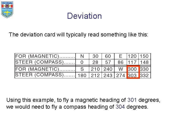
Deviation • Compass deviation is unique to each individual airplane and is the result of compass interference caused by metals and electrons in the vicinity of the wet compass. • Magnetic heading correct for Deviation = Compass Heading • A compass deviation card is located very near the wet compass so that pilots may correct their magnetic heading for that error.
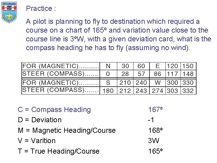
Deviation The deviation card will typically read something like this: Using this example, to fly a magnetic heading of 301 degrees, we would need to fly a compass heading of 304 degrees.
True and Magnetic Values • Course and Heading – Course is always the line draw on the chart. – Heading is always a direction measured relative to the longitudinal axis of the air plane. • True course correct for the wind = True heading • Magnetic course correct for the wind = Magnetic heading
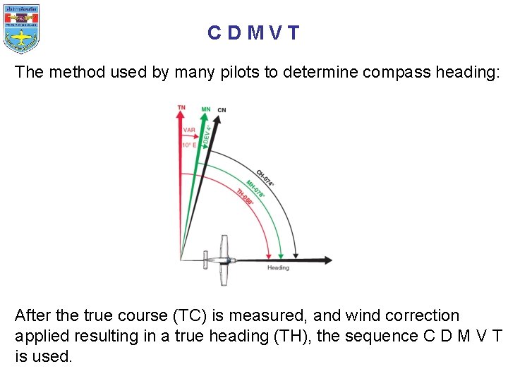
CDMVT The method used by many pilots to determine compass heading: After the true course (TC) is measured, and wind correction applied resulting in a true heading (TH), the sequence C D M V T is used.
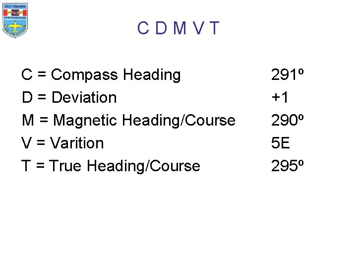
C D M V T C = Compass Heading D = Deviation M = Magnetic Heading/Course V = Varition T = True Heading/Course 291º +1 290º 5 E 295º
Practice : A pilot is planning to fly to destination which required a course on a chart of 165º and variation value close to the course line is 3ºW, with a given deviation card, what is the compass heading he has to fly (assuming no wind). C = Compass Heading D = Deviation M = Magnetic Heading/Course V = Varition T = True Heading/Course 167º -1 168º 3 W 165º
Navigation Introduction • Word NAVIGATION came from two Latin words: – NAVIS: ship – AGERE: to direct or move • Navigation means finding your way. • Navigation is the art and science of getting from point "A" to point "B" in the least possible time without losing your way.
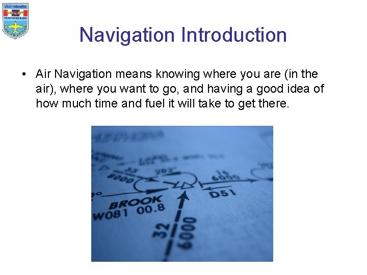
Navigation Introduction • Air Navigation means knowing where you are (in the air), where you want to go, and having a good idea of how much time and fuel it will take to get there.
The type of navigation used by pilots depends on many factors. • • Where the pilot is going. How long the flight will take. When the flight is to take off. The type of aircraft being flown. The on-board navigation equipment. The ratings and currency of the pilot. The expected weather.
Pilotage and dead reckoning • The two most fundamental methods of finding your way in an airplane are Pilotage and Dead Reckoning. • These two methods normally are used together, each acting as a cross-check of the other.
Pilotage • Is the identification of present position and direction of flight by seeing features on the ground. • Pilotage is mainly used by pilots of small, low speed aircraft who compare symbols on aeronautical charts with surface features on the ground in order to navigate.
Pilotage disadvantages • Poor visibility caused by inclement weather can prevent a pilot from seeing the needed landmarks and cause the pilot to become disoriented and navigate off course. • A lack of landmarks when flying over the more remote areas can also cause a pilot to get lost.
• Using pilotage for navigation can be as easy as following a highway or a railroad.
Three basic tasks of pilotage navigation are : • Create a course • Fly on course • Make position check
• before take-off, pilot will making pre-flight planning by drawing a line on the aeronautical map to indicate the desired course. • Then notes various landmarks , such as highways , railroad tracks, rivers , bridges. • As the pilot flies over each of landmark , he will checks it off on the chart or map. • If the plane does not pass directly over the landmark, he will know that he has to correct the course.
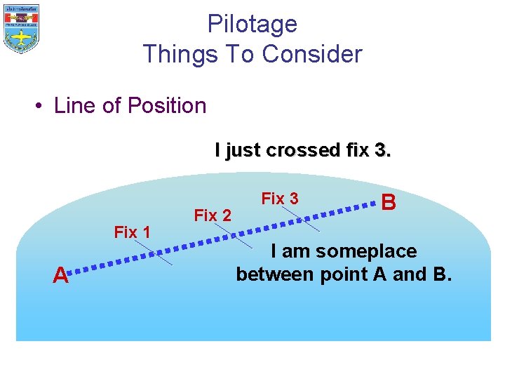
Pilotage Things To Consider • Line of Position (LOP) – LOP is the simple concept that the airplane is locate somewhere along a specific line. – LOP doesn’t establish the exact position, but rather a line of possible positions. – The intersection of two different LOP is a FIX
Pilotage Things To Consider • Line of Position I just crossed fix 3. Fix 1 A Fix 2 Fix 3 B I am someplace between point A and B.
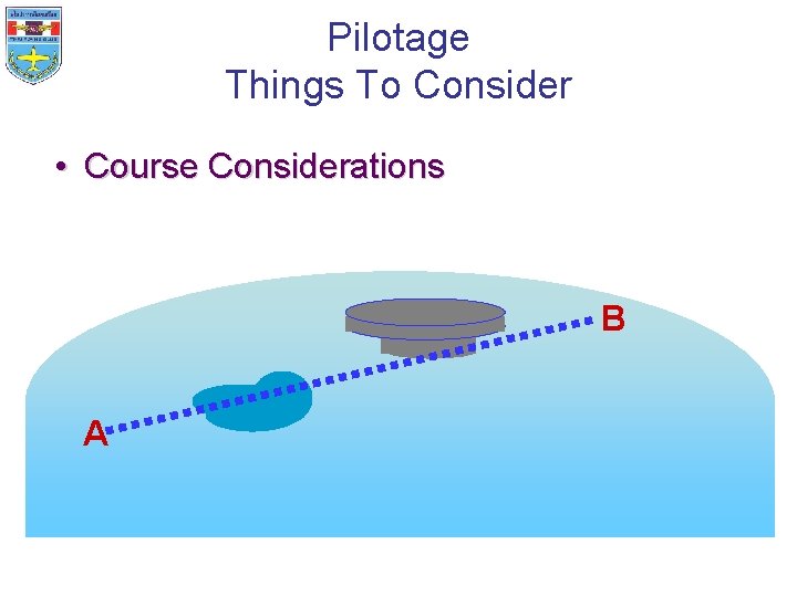
Pilotage Things To Consider • Course Considerations B A
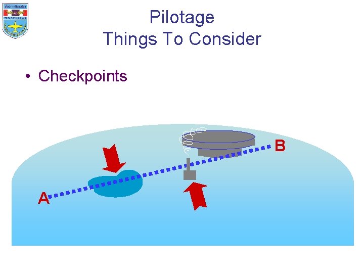
Pilotage Things To Consider • Checkpoints B A
Checkpoints Note • The checkpoints selected should be prominent features common to the area of the flight. • Choose checkpoints that can be readily identified by other features such as roads, rivers, railroad tracks, lakes, and power lines. • If possible, select features that will make useful boundaries or brackets on each side of the course, such as highways, rivers, railroads, and mountains.
Pilotage Tip • Never place complete reliance on any single checkpoint. Choose ample checkpoints. If one is missed, look for the next one while maintaining the heading. • If confused, hold the heading. If a turn is made away from the heading, it will be easy to become lost. • Aeronautical charts display the best information available at the time of printing, but a pilot should be cautious for new structures or changes that have occurred since the chart was printed.
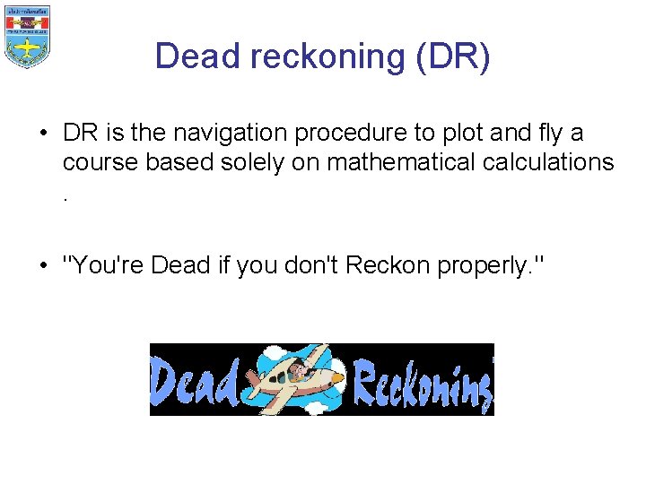
Dead reckoning (DR) • DR is the navigation procedure to plot and fly a course based solely on mathematical calculations . • "You're Dead if you don't Reckon properly. "
Dead reckoning • DR is the process of estimating your position by advancing a known position using course, speed, time and distance to be traveled. • In other words figuring out where you will be at a certain time if you hold the speed, time and course you plan to travel.
Dead reckoning Procedures 1. Open air navigation chart and select departure airport and destination airport. 2. Draw a straight line from the center of the runway symbol at the departure airport to the destination airport. Avoid Prohibit and Restrict Area and note others special used airspace. 3. Find the nearest north-south running tick marked line. This is a line of longitude. 4. Measure the angle between the north-south line of longitude and the direction of flight. This angle is called the TRUE COURSE (TC).
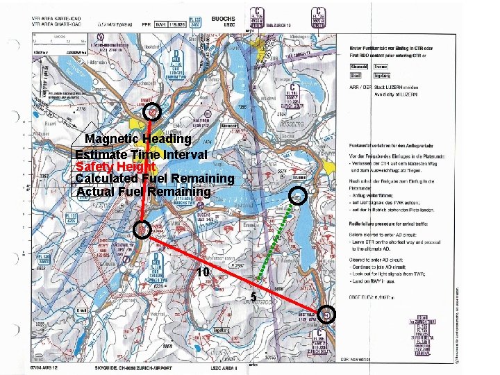
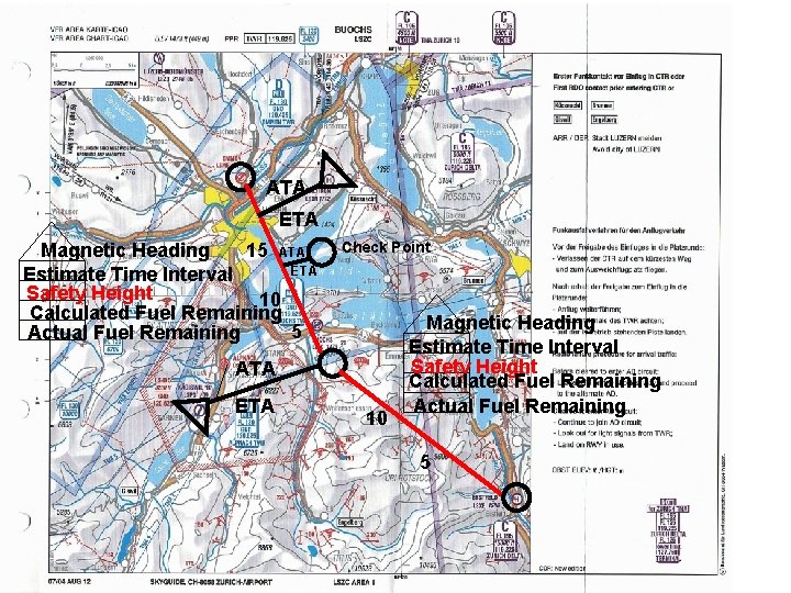
Dead reckoning Procedure 5. Measure distance by using distance bar on the map. Or using minutes and second scale on latitude (1 minute of latitude = one nautical mile) 6. Mark distance along course line. 7. Mark any check point with circle. 8. Mark alternate airfield with triangle. 9. Note safety height along the routes. 10. Draw Information boxes and fill in necessary data.
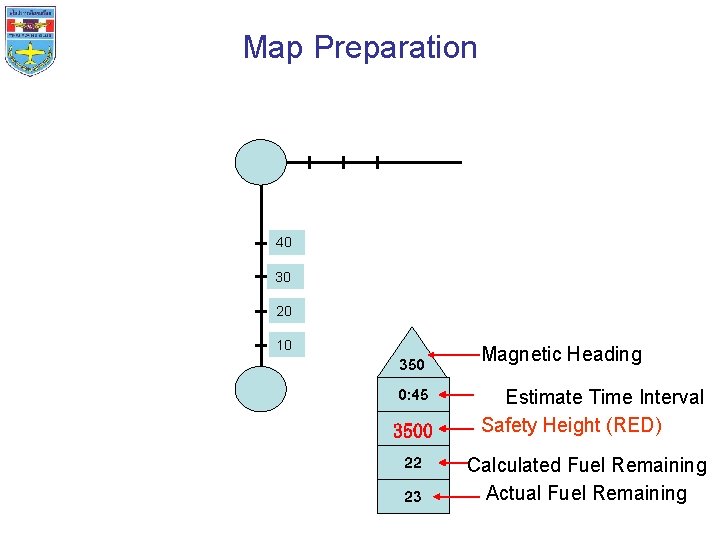
Map Preparation • TURNING POINT 40 30 20 • INFORMATION BLOCK 10 350 0: 45 Magnetic Heading 3500 Estimate Time Interval Safety Height (RED) 22 23 Calculated Fuel Remaining Actual Fuel Remaining
Magnetic Heading Estimate Time Interval Safety Height Calculated Fuel Remaining Actual Fuel Remaining 10 5
ATA ETA Magnetic Heading 15 ATA Estimate Time Interval Safety Height 10 Calculated Fuel Remaining 5 Actual Fuel Remaining Check Point ATA ETA 10 Magnetic Heading Estimate Time Interval Safety Height Calculated Fuel Remaining Actual Fuel Remaining 5
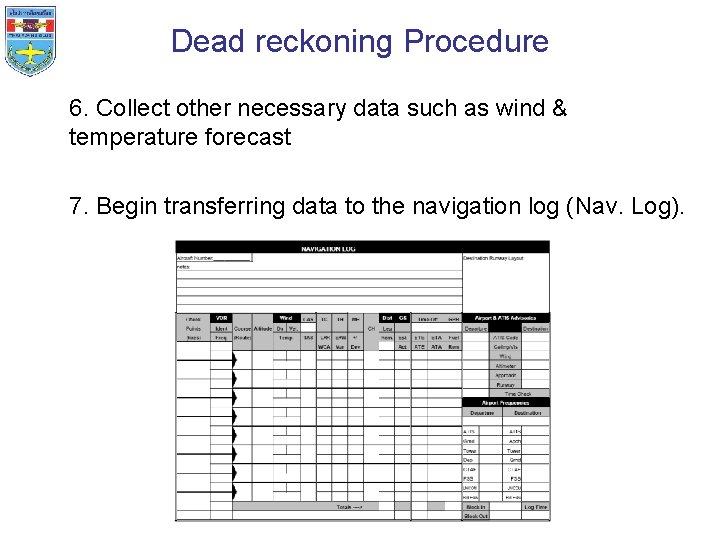
Dead reckoning Procedure 6. Collect other necessary data such as wind & temperature forecast 7. Begin transferring data to the navigation log (Nav. Log).
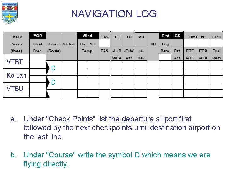
NAVIGATION LOG VTBT D Ko Lan VTBU D a. Under "Check Points" list the departure airport first followed by the next checkpoints until destination airport on the last line. b. Under "Course" write the symbol D which means we are flying directly.
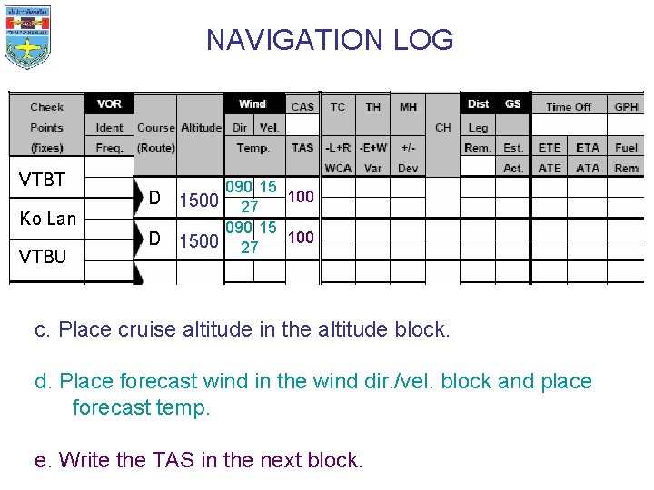
NAVIGATION LOG VTBT D Ko Lan VTBU D 090 15 100 1500 27 c. Place cruise altitude in the altitude block. d. Place forecast wind in the wind dir. /vel. block and place forecast temp. e. Write the TAS in the next block.
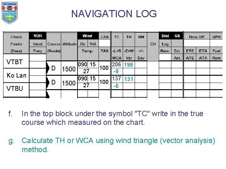
NAVIGATION LOG VTBT D Ko Lan VTBU f. D 090 15 206 198 100 1500 27 -8 090 15 137 131 100 1500 27 -6 In the top block under the symbol "TC" write in the true course which measured on the chart. g. Calculate TH or WCA using wind triangle (vector analysis) method.
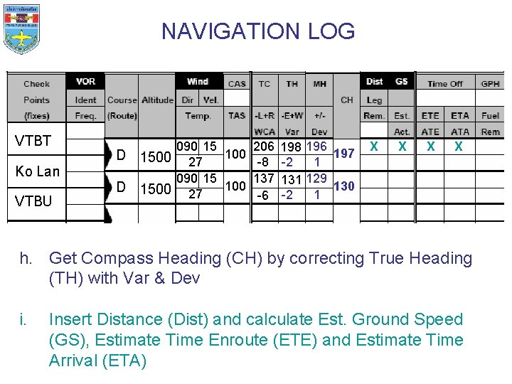
NAVIGATION LOG VTBT D Ko Lan VTBU D 090 15 206 198 196 197 100 1500 27 -8 -2 1 090 15 137 131 129 100 130 1500 27 1 -6 -2 X X h. Get Compass Heading (CH) by correcting True Heading (TH) with Var & Dev i. Insert Distance (Dist) and calculate Est. Ground Speed (GS), Estimate Time Enroute (ETE) and Estimate Time Arrival (ETA)