Chapter 2 Pneumatic Component Control Valves Prepared by

Chapter 2 Pneumatic Component: Control Valves Prepared by: Mohd Shahril Shariff

Pneumatic Control Valve ü Valve are defined as devices to control or regulate the commencement, termination and direction and also the pressure or rate of flow of a fluid under pressure which is delivered by a compressor or vacuum pump or is stored in a vessel(receiver tank) ü The form of control energy will be dictated by the valve’s mode of actuation and my be manual, mechanical, electrical, hydraulic or pneumatic. ü Valve available for pneumatic control can be classified according to their function: v. Direction control valve v. Non return valves v. Flow control valves v. Pressure control valves
 The function of directional control valve is to control the")
Direction Control Valves (DCV) The function of directional control valve is to control the direction of flow in the pneumatic circuit. DCVs are used to start, stop and regulate the direction of air flow and to help in the distribution of air in the required line. Types of Direction Control Valves Directional valves control the way the air passes and are used principally for controlling commencement, termination and direction of air flow. The different classification scheme of the pneumatic valve are given below

Types of Direction Control Valves Parameter Criterion Based on the number of ports 2 way valve, 3 way valve, 4 way valve, 5 way valve Based on the number of position 2 -position, 3 -position Based on method of actuation Manual, mechanical, electrical, pneumatic, combination Poppet/seat valve Based on construction Ball seat valve Disc seat valve Diaphragm valve Sliding valve Longitudinal slide valve(spool valve) Longitudinal flat slide valve Rotary valve/Plate slide valve

BASED ON THE NUMBER OF PORTS Port ISO 5599 Lettering system Pressure port 1 P Exhaust port 3 R (3/2 DCV) Exhaust ports 5, 3 R, S (5/2 DCV) 2 A(3/2 DCV) Signal Outputs/working ports 2, 4 B, A (4/2 or 5/2 DCV) Pilot line opens flow 1 to 2 12 Z (single pilot 3/2 way Pilot line opens flow 1 to 4 14 Z ( 5/2 DCV) Signal output/working port

The use of Directional Control Valve Symbols

The use of Directional Control Valve Symbols Type of Valve Symbol Function 2/2 DCV Drives the air motor and pneumatic equipment 3/2 DCV N/C Drive a single acting cylinder or acts as a switch "on / off". 3/2 DCV N/O Drive a single acting cylinder 4/2 DCV Drive the Double-acting cylinder with one exhaust to release air. 4/3 DCV close centre Drive the Double-acting cylinder with the ability to stop the cylinder in any position to prevent air in the cylinder from the exit.

The use of Directional Control Valve Symbols Type of Valve Symbol Function 5/2 DCV Drives the double acting cylinder with individual exhaust 5/3 DCV Exhaust centre Double-acting cylinder drive with the ability to stop the cylinder at any position by releasing the air in the cylinder. 5/3 DCV Close centre Double-acting cylinder drive with the ability to stop the cylinder in any position to prevent air in the cylinder from the exit. 5/3 DCV Pressure centre Stopping in the middle of the cylinder rod to balance the air simultaneously in the bows and rear cylinders

Example of Directional Control Valve 2/2 Way Directional Control Valve

Example of Directional Control Valve 3/2 Way Directional Control Valve

Example of Directional Control Valve 5/2 Way Directional Control Valve

BASED ON THE METHOD OF ACTUATION Actuation method of valve Manual Powered by the operator by pressing the buttons provided Type of control General operated Push button operated Lever operated Detent lever operated(hold position) Mechanical Valve is actuated by a mechanical mechanism such as a switch wheel and the cylinder rod. Foot pedal operated Spring return Spring centered Roller operated Idler roller operated Symbol Example Figure construction

Actuation method of valve Pneumatic Valve is actuated by compressed air which acts move the wind channel. Electrical Actuated by a solenoid valve which is generated by electricity Combined Valve actuated by combination of double solenoid and pneumatic(pilot) Type of control pilot operated Single solenoid Double solenoid with double pilot operated with manual override Symbol Example figure construction

Example of Directional Control Valve 3/2 DCV normally closed, single pilot operated, spring return 5/2 DCV, double pilot operated, manual override

BASED ON CONSTRUCTION • Poppet valves with poppet valves the connections are opened and closed by means of balls, discs, plates or cones. • Slide valves in slide valves, the individual connections are linked together or closed by means of spools, flat slide or plate slide valves.
 (a) P-DCV: Disc seat poppet valve (P Figure shows")
POPPET DIRECTION CONTROL VALVES -DCV) (a) P-DCV: Disc seat poppet valve (P Figure shows the construction of a disc type 3/2 way DCV. When push button is released, ports 1 and 3 are connected via hollow pushbutton stem. If the push button is pressed, port 3 is first blocked by the moving valve stem and then valve disc is pushed down so as to open the valve thus connecting port 1 and 3. When the push button is released, spring and air pressure from port 1 closes the valve.
 P-DCV: Ball seat valve • In a poppet valve, discs, cones or balls")
(b) P-DCV: Ball seat valve • In a poppet valve, discs, cones or balls are used to control flow. The construction of a simple 2/2 normally closed valve. If the push button is pressed, ball will lift off from its seat and allows the air to flow from port P to port B. When the push button is released, spring force and air pressure keeps the ball back and closes air flow from port P to port B.
 P-DCV: Diaphragm valve The diaphragm between the actuator and valve body hermetically isolates")
(c) P-DCV: Diaphragm valve The diaphragm between the actuator and valve body hermetically isolates the fluid from the actuator. The valves are maintenance-free and extremely robust and can be retrofitted with a comprehensive range of accessories, e. g. electrical position feedback, stroke limitation or manual override. Figure shows unactuated and actuated position of diaphragm valves. Closed position: When de-energized, the valve is closed by spring action Open position: If the actuator is pressurized by the control pressure, it simultaneously lifts the control piston and the valve spindle to open the valve.
 3 types of Slide Direction Control Valve v Longitudinal slide")
Slide-Direction Control Valve (S-DCV) 3 types of Slide Direction Control Valve v Longitudinal slide valve (spool valve) v Longitudinal flat slide valve v Rotary valves
 3/2 DCV, manual operated, with spring return -spool valve • The cross sectional")
(a) 3/2 DCV, manual operated, with spring return -spool valve • The cross sectional views of 3/2 DCV (normally closed) based on spool design is shown in Fig. When the valve is not actuated, port 2 and 3 are connected and port 1 is blocked. When the valve is actuated then port 2 and 1 are connected and port 3 is blocked. • Figure shows schematic diagram of 3/2 spring operated valve. There are three ports common port, normally open port and normally closed. When the valve is not actuated, there is flow from NO port to common port. When the valve is actuated there is flow from NC to common port.
 - To control Single")
Applications: - As input signal (pushbutton, limit switch, emergency button) - To control Single Acting Cylinder
 3/2 DCV, single air operated, with spring return -spool valve • The cross")
(b) 3/2 DCV, single air operated, with spring return -spool valve • The cross – sectional views of pneumatically actuated NC type 3/2 DCV in normal position and actuated positions are shown in the Figure 1. 7 • In normal position, the working port (2) is closed to the pressure port (1) and open to the exhaust port (3). When the compressed air is applied through the pilot port (12), the spool is moved against the spring. In the actuated position, the working port (2) is open to the pressure port(1) and closed to the exhaust port(3). Thus, the application of the compressed air to the port 12 causes the pressure port (1) to be connected to the working port (2).
 - To control Single")
Applications: - As input signal (pushbutton, limit switch, emergency button) - To control Single Acting Cylinder
 4/2 DCV, double pilot operated-spool valve • The valve shown in Figure is")
(c) 4/2 DCV, double pilot operated-spool valve • The valve shown in Figure is a 4/2 way valve pneumatically operated DCV. Switch over is effected by direct application of pressure. If compressed air is applied to pilot spool through control port 12, it connects port 1 with 2 and 4 is exhausted through port 3. If the pilot pressure is applied to port 14, then 1 is connected with 4 and line 2 exhausted through port 3. On disconnecting the compressed air from the control line, the pilot spool remains in its current position until spool receives a signal from the other control side.
 Longitudinal flat slide Valve • This valve is quite similar to 4/2 way")
(d) Longitudinal flat slide Valve • This valve is quite similar to 4/2 way spool valve. Schematic diagram is shown in Figure. In this design disc is used instead of a spool. This suspended disc can be moved by pilot pressure or by solenoid or by mechanical means. In this design, main disc connects port 1 to either port 4 or 2. The secondary seat discs seal the exhaust port 3 whichever is not functional. These values are generally provided with manual override to manually move the cylinder.

Figure show 5/2 way valve which uses suspended disc instead of spool. In spool type valve, spool controls the opening and closing of ports. In this type, suspended disc controls the opening and closing of ports. This suspended disc can be moved by pilot pressure at port 14 or port 12. When the pilot pressure acts through port 14. The ports 1 - 2 and 4 - 5 are connected and 3 is blocked. When the air is given to pilot line 12, then 2 - 3 and 4 -1 are connected and 5 is blocked
 Rotary valves • The rotary valve has a round core with one or")
(e) Rotary valves • The rotary valve has a round core with one or more passages or recesses in it. The core is mounted within a stationary sleeve. As the core is rotated within the stationary sleeve, the passages or recesses connect or block the ports in the sleeve. The ports in the sleeve are connected to the appropriate lines of the fluid system.

Table below shows schematically the different position of core and sleeve for various middle position of 4/3 way Direction control valve.
 • Non return valves permit flow of air in one direction")
Non-Return Valve (NRV) • Non return valves permit flow of air in one direction only, the other direction through the valve being at all times blocked to the air flow. Mostly the valves are designed so that the check is additionally loaded by the downstream air pressure, thus supporting the non-return action. • Among the various types of non-return valves available, those preferentially employed in pneumatic controls are as follows i) Check valve/Spring-loaded check valve ii) Shuttle valve iii) Restrictor check valve/one-way flow control valve iv) Quick exhaust valve v) Two pressure valve
 Check Valve and Spring-loaded check valve • The simplest type of non-return valve")
i) Check Valve and Spring-loaded check valve • The simplest type of non-return valve is the check valve, which completely blocks air flow in one direction while permitting flow in the opposite direction with minimum pressure loss across the valve. As soon as the inlet pressure in the direction of free flow develops a force greater than that of the internal spring, the check is lifted clear of the valve seat. The check in such valve may be plug, ball, plate or diaphragm. free flow No flow
 Shuttle Valve (OR) • 2 input and 1 output • Allow a signal")
ii) Shuttle Valve (OR) • 2 input and 1 output • Allow a signal to flow in one direction • Output is acquired if one (or both) of input supply pressure • For circuit with more than 1 input signal

Circuit Diagram without Shuttle Valve Circuit Diagram with Shuttle Valve
")
Circuit Diagram with Shuttle Valve (Actuated)
 Restrictor check valve/one-way flow control • 1 input and 1 output. • To")
iii) Restrictor check valve/one-way flow control • 1 input and 1 output. • To reduce speed of piston movement (adjustable)

Supply Air Throttling • Supply air entering the cylinder through either of the working ports, undergoes throttling as the non return valve is closed in the direction of flow. • During exhaust , the compressed air leaving the cylinder is by passed through the non return valve and escapes freely as it does not under go throttling • Supply air throttling is used for single acting cylinder and small volume cylinder

Exhaust Air Throttling • Supply air flows freely to the cylinder through the bypassage of the non return valve. The supply air does not under go any throttling • Exhaust air leaving the cylinder has to under go throttling as the non return valve is closed in the return direction • The piston is loaded between two cushions of air • Exhaust throttling should always be used for double acting cylinder • Not suitable for small volume cylinders and cylinders with short strokes as effective pressure cannot build up sufficiently.

EXAMPLE Liquid metal is drawn from a smelting crucible by a casting ladle and cast in moulds. The raising and lowering of the ladle is controlled by separate manual general. The raising and lowering speed is separately adjustable. Design a Pneumatic control circuit for this application
 Quick Exhaust Valves A quick exhaust valve is a typical shuttle valve. The")
iv) Quick Exhaust Valves A quick exhaust valve is a typical shuttle valve. The quick exhaust valve is used to exhaust the cylinder air quickly to atmosphere. In many applications especially with single acting cylinders, it is a common practice to increase the piston speed during retraction of the cylinder to save the cycle time. The higher speed of the piston is possible by reducing the resistance to flow of the exhausting air during the motion of cylinder. The resistance can be reduced by expelling the exhausting air to the atmosphere quickly by using Quick exhaust valve. silencer • 1 input, 1 output, 1 exhaust

Quick Exhaust Valve during Forward Motion Quick Exhaust Valve during Return Motion

The construction and operation of a quick exhaust valve is shown in Figure above. It consist of a movable disc (also called flexible ring) and three ports namely, Supply port 1, which is connected to the output of the final control element (Directional control valve). The Output port, 2 of this valve is directly fitted on to the working port of cylinder. The exhaust port, 3 is left open to the atmosphere
 Two Pressure Valve (AND) This valve is the pneumatic AND valve. It is")
v) Two Pressure Valve (AND) This valve is the pneumatic AND valve. It is also derivate of Non Return Valve. A two pressure valve requires two pressurised inputs to allow an output from itself. As shown in the figure, this valve has two inputs 12 and 14 and one output 2. If the compressed air is applied to either 12 or input 14, the spool moves to block the flow, and no signal appears at output 2. If signals are applied to both the inputs 12 and 14, the compressed air flows through the valve, and the signal appears at output 2.

And Gate Combination

Flow Control Valve Function of a flow control valve is self –evident from its name. A flow control valve regulates the rate of air flow. The control action is limited to the air flow passing through the valve when it is open, maintaining a set volume per unit of time. Figure (a) shows a variable restrictor type flow control valve (manifold type). Figure (b) shows a variable restriction type flow control valve (inline type). Another design of Flow control valve, in which flow can be set by turning the knob.

Pressure Control Valve Pressure may gradually buildup due to decrease in fluid demand or due to sudden surge as valves opens or closes. Pressure control valves protect the system against such overpressure. There are three types of pressure control valves 1. Pressure limiting valve/relief valve 2. Pressure sequence valve 3. Pressure regulator or pressure reducing valve

PCV: Pressure Limiting Valve/Relief Valve Prevents the pressure in a system from rising above a permissible maximum. Construction feature of pressure limiting valve is shown in Figure. It is a standard feature of compressed air production plant but is hardly ever used in pneumatic controls. These valves perform a safety relief function by opening to the atmosphere if a predetermined pressure is exceeded in the system, thus releasing the excess pressure. As soon as the pressure is thus relieved to the desired figure, the valve closed again by spring force.

PCV: Pressure Sequence Valve • Pressure Sequence valve is essentially a switch on or off valve • Sequence Valve generates a pneumatic signal if the sensing pressure [signal input] is more than the desired set pressure • This generated out put signal is used to control the movement of cylinder by using it as a set signal or reset signal to the final control valve to obtain forward or return motion respectively • Used for applications such as bonding cylinders, clamping cylinder etc. to ensure desired minimum pressure in the cylinder • This is a combination valve, having two sections. One of the section is a 3/2 directional control and the other a pressure control valve

Sensing pressure signal is introduced at port 12. Manual adjustment of pressure setting is done with the help of a cap screw/knob which is spring loaded. Clock wise rotation of knob results setting for higher pressure setting and anticlockwise rotation of knob results in lower pressure setting. The right section is basically a 3/2 directional control valve [NC] pilot operated using pressure signal derived from left section.

Adjustable Pressure Sequence Valve. Actuated

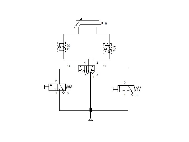
Example 1

Example 1 Solution All valves are unactuated in the initial position. Pressure is applied at the piston rod side of the cylinder and the piston rod remain in the retracted status. Actuation of the push button switches the valve 3/2 DCV to flow and a signal is applied at the control port 14 of the double pilot valve 5/2 DCV. The valve 5/2 DCV switches, pressure is applied at the piston side of the cylinder and piston rod advances. The switching status of the double pilot valve 5/2 DCV remain intact if the push button is released. When the piston rod reaches the workpiece, travel is stopped and pressure starts to build up on the piston side. The increasing pressure causes the force of the die to increase.
 The control port 12 of the pressure sequence valve is")
Example 1 (continue…. ) The control port 12 of the pressure sequence valve is connected to the pressure line on the piston side of the cylinder. When the pressure in the cylinder reaches the valve set on the pressure sequence valve, the 3/2 DCV valve switches. A signal is now applied at the control port 12 the 5/2 DCV. The valve 5/2 DCV switches, pressure is applied at the piston rod side of the cylinder and the piston rod retracts. During retraction, the response pressure set on the pressure sequence valve is not met and the pressure sequence valve return to its initial position.

PCV: Pressure reducing valve or regulator Pressure regulators, commonly called pressure-reducing valves, maintain constant output pressure in compressedair systems regardless of variations in input pressure or output flow. Regulators are a special class of valve containing integral loading, sensing, actuating, and control components. Available in many configurations, they can be broadly classified as general purpose, special purpose, or precision. Three dimensional view of pressure reducing valve is shown in

Others Control Valve Time Delay valve • Pneumatic Timers are used to create time delay of signals in pilot operated circuits. • Available as Normally Closed Timers and Normally Open Timers. • Usually Pneumatic timers are On Delay Timers Delay of signals is very commonly experienced in applications such as Bonding of two pieces. • Normally Open Pneumatic Timer are also used in signal elimination • Normally Open Pneumatic Timers are used as safety device in Two Hand Blocks
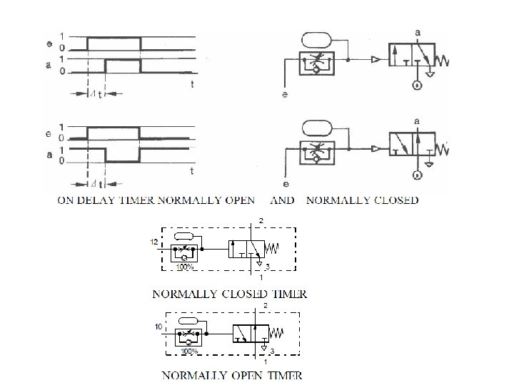

A Pneumatic Timer is a combination valve which consists of three parts 1. 3/2 way pilot operated directional control valve [NC or NO], 2. A one way flow control valve and 3. An accumulator is simply an empty container, just like an empty bottle. The bigger the accumulator, the longer it takes to fill up with air. To make the delay longer we use a one way flow control valve in front of the accumulator. This slows down the air so that the accumulator takes even longer to fill. The length of time it takes to fill creates the delay.
![Time Delay Valve [N. C] Signal input is supplied at port 1 and delayed](http://slidetodoc.com/presentation_image/5978eff6081c32386eb6e11a5eaa11d2/image-58.jpg "Time Delay Valve [N. C] Signal input is supplied at port 1 and delayed")
Time Delay Valve [N. C] Signal input is supplied at port 1 and delayed signal out put is taken at 2. A signal source is connected at port 1

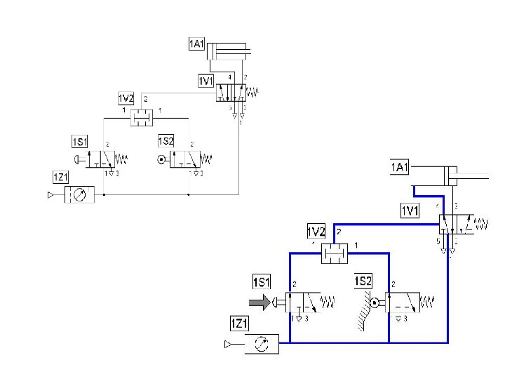
Example 2

Solution:

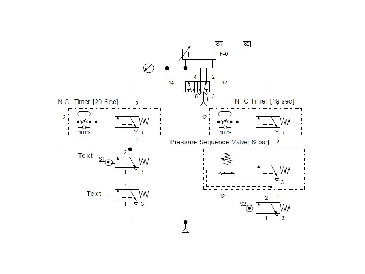
Example 3: Bonding Application Plastic Cylinders are to be bonded using a Pneumatic cylinder. It is required that piston performs forward stroke on actuation of a hand push button. Return motion should take place after the piston reaches forward end position cylinder attains full pressure of 6 bar and remains in that position for 10 sec. It should be possible to restart the forward motion only 20 sec after the piston reaches home position.
- Slides: 62