Unit 6 Regulated power supply 6 1 Regulated


 Vin")


 • UPS are used to feed the critical a. c. loads")
")

")

")


- Slides: 24
Unit- 6 Regulated power supply
6. 1 Regulated power supply • Regulated power supply is an electronic circuit that is designed to provide a constant dc voltage of predetermined value across load terminals irrespective of ac mains fluctuations or load variations.
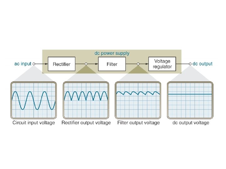
Block Diagram
Simple Description • Transformer: “Downconvert” the AC line voltage to a smaller peak voltage Vm, usually about 2 -3 Volts larger than the ultimately desired DC output. • Diode Rectifier Circuit: produce a waveform with large DC component. • Filter: smooth out the rectified sinusoid. • Regulator: eliminate residual ripple
Vout = the change in output voltage (usually in microvolts or millivolts) Vin = the change in input voltage (usually in volts) VNL VFL IL = the no-load output voltage (i. e. , the output voltage when the load is open) = the full-load output voltage (i. e. , the load current demand is at its maximum value) = the change in load current demand
6. 2 Zener diode shunt regulator
Zener diode shunt regulator • One of the most common and simple forms of shunt regulator is the simple Zener diode regulator circuit shown below. Its operation is very straightforward. • Once over its small minimum current, the Zener diode maintains an almost constant voltage across its terminals. • The series resistor drops the voltage from the source to the Zener diode and load. • As the Zener diode maintains its voltage, any variations in load current do not affect the voltage across the Zener diode. • It takes up the current variations required to ensure the correct drop across the series resistor
• Types of Regulators – Series Regulator – Shunt Regulator
• 6. 3 Series Regulators – circuits that have one or more devices placed in series with the load – Pass-Transistor Regulator – a circuit that uses a series transistor to regulate load voltage A decrease in VL causes VBE to increase, which increases conduction through the pass transistor and a relatively constant load voltage is maintained
Shunt Feedback Regulator Shunt Regulator – a circuit that has a regulating transistor in parallel with the load Shunt Feedback Regulator – a circuit that uses an error detection circuit to control the conduction through a shunt regulator transistor Shunt Feedback Regulator
6. 4 Fixed Voltage Regulators • These regulators provide a constant output voltage. A popular example is the 7805 IC which provides a constant 5 volts output. A fixed voltage regulator can be a positive voltage regulator or a negative voltage regulator. A positive voltage regulator provides with constant positive output voltage. All those IC’s in the 78 XX series are fixed positive voltage regulators. In the IC nomenclature – 78 XX ; the part XX denotes the regulated output voltage the IC is designed for. Examples: - 7805, 7806, 7809 etc. • A negative fixed voltage regulator is same as the positive fixed voltage regulator in design, construction & operation. The only difference is in the polarity of output voltages. These IC’s are designed to provide a negative output voltage. Example: - 7905, 7906 and all those IC’s in the 79 XX series.
Adjustable Voltage Regulator • An adjustable voltage regulator is a kind of regulator whose regulated output voltage can be varied over a range. There are two variations of the same; known as positive adjustable voltage regulator and negative adjustable regulator. • LM 317 is a classic example of positive adjustable voltage regulator, whose output voltage can be varied over a range of 1. 2 volts to 57 volts. LM 337 is an example of negative adjustable voltage regulator. • LM 337 is actually a complement of LM 317 which are similar in operation & design; with the only difference being polarity of regulated output voltage.
Power supply – Linear IC Voltage Regulators – a device that is used to hold the output voltage from a dc power supply relatively constant over a specified range of line and load variations n Basically Four Types Fixed-Positive – provide a specific positive voltage Fixed-Negative – provide a specific negative voltage Adjustable – can be adjusted within a specified range of values Dual-Tracking – provides equal positive and negative output voltages
Fixed-Negative – provide a specific negative voltage
Power supply – Linear IC Voltage Regulators Adjustable Regulators – Example LM 317
UPS(uninterrupted power supply) • UPS are used to feed the critical a. c. loads in case of failure of the main supply. • There are two arrangements of the UPS. • 1. critical load normally connected to the a. c. mains. • 2. critical load connected to the inverter.
UPS(load connected to the a. c. Mains)
Features of arrangement • Circuit is broken momentarily for 4 to 5 ms when ststic switches are used and for 30 to 50 ms when electromechanical relays are used. • Inverters runs only during the time when supply failure occures. • The load is not saved from the switching transients of the a. c. mains.
UPS (load is connected to inverter)
Features of arrangement • • Critical load is supply from the inverter. Inverter is continuously on. There is no interruption of the supply to the critical load. The load is protected from the transients of the mains supply as the load is not connected to the mains.
SMPS(switch mode power supply)
Principle of SMPS • • • In this switching device transistor is driven by square wave. It is fully turned ON when mark comes. So potential difference across it is zero. And when the space comes, the transistor is turned OFF. So current passing through the transistor is zero. So the power dissipation is zero.
Working of SMPS • Main a. c. voltage is rectified and converted in to d. c. which is filtered by capacitor c 1. • This d. c. is converted in to high frequency a. c. by the chopper controlled by the multivibrator. • This high frequency is stepped down by the transformer. This low voltage a. c. is converted in to d. c. • This is smoothed out by the ∏ filter. This d. c. is given to the load. • If the output voltage decreases the error signal changes which is amplified. This increases the duty of the square wave , this increases the magnitude of the a. c. voltage coming out from the chopper. so output increases.