
The Bureau of Automotive Repair Presents The 2007
The Bureau of Automotive Repair Presents: The 2007 Smog Check Technician Update Course written by Wayne Brumett
This course will provide an overview of the following: Ø Review of Computer Control Systems Interaction and Advanced Fuel Trim Diagnostics. Ø Networking and Controller Area Network (CAN). Ø OBD II - Mode 6 Diagnostics. Ø OBD II Evaporative Emission Control Systems. Ø Technical Service Bulletins and using Manufacturers’ Internet sites. Ø Computer Program Re-flashing. Ø BAR Program Updates. 2
NOTICE TO TECHNICIANS: BAR update courses are designed to provide Smog Check Technicians with Information on Program Changes and New Technology that can Affect the Smog Check Program. This course is not designed to teach you in-depth information on a particular subject area (e. g. Mode 6, EVAP Diagnostics, CAN, etc. ). As a professional automotive technician, you are expected to educate yourself (i. e. attend courses, read publications & training manuals, etc. ) to complement your understanding of this 3 training course material.

To pass this course, you must: must • Read the entire course textbook (prior to the course). • Read the two Motor Magazine articles (supplied by your school/instructor) on “CAN” and evaporative (EVAP) system diagnosis. • Turn in for credit the 50 question quiz in the textbook on the first day of class. • Successfully complete all the laboratory examinations. • Attend all course hours. • Pass the written final examination (with a score of 70% or better). 4
Engine Control System Operating Strategy - Overview The Input/Output Relationship
Introduction Engine Control System Operating Strategy is: A programmed strategy in the Powertrain Control Module (PCM), that determines how sensor input information will be calculated, and what PCM output commands will be sent to the various actuators that control vehicle operation, based on those sensor inputs. As a technician, it is important for you to understand the relationship between input values and output commands. 6
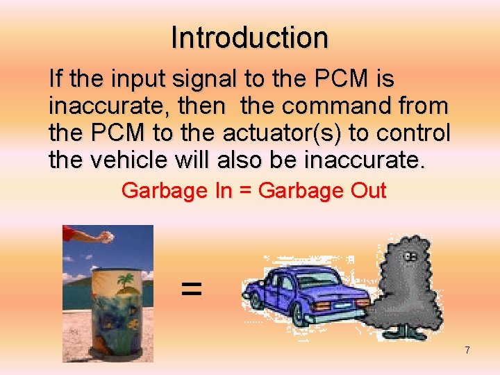
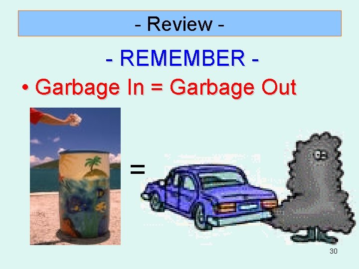
Introduction If the input signal to the PCM is inaccurate, then the command from the PCM to the actuator(s) to control the vehicle will also be inaccurate. Garbage In = Garbage Out = 7
SENSORS AND FUEL TRIM REVIEW 8
Review of Sensor/PCM Interaction • The following information is the minimum needed for the engine controller to properly control the air/fuel mixture and ignition timing events: – – – – – Engine RPM Engine Load (MAP / MAF) Driver Demand (TPS) Engine Coolant Temperature (ECT) Barometric Pressure (BARO) Intake Air Temperature (IAT) Vehicle Speed (VSS) Battery Voltage Oxygen Sensor (O 2 - used for fine tuning) 9
Sensor/PCM Interaction - Review • Calculating basic injector pulse width: – Engine RPM – Engine Load (MAP / MAF) • Sensor inputs used to modify basic pulse width: – Driver Demand (TPS) – Barometric Pressure (BARO) – Engine Coolant Temperature (ECT) – Intake Air Temperature (IAT) – Vehicle Speed (VSS) – Battery Voltage – Oxygen Sensor (used for fine tuning) 10
Sensor/PCM Interaction - Review • • • Injector pulse width is calculated based on sensor inputs, and fine tuned utilizing the oxygen sensor input(s). The computer compensates for variations in engine mechanical, electrical and sensor tolerances that develop over the vehicle life span, using Long Term Fuel Trim (LTFT) and Short Term Fuel Trim (STFT) values. LTFT corrections are made to move STFT towards the middle of the fuel 11 correction scale.
Sensor/PCM Interaction - Review The computer operates in either Open or Closed loop. • Open Loop: – The oxygen sensor is ignored and signals from the other sensors, that are used to provide a basic pulse, are evaluated. The computer matches these conditions with values stored in memory (look-up tables) and issues commands to outputs devices (e. g. injector pulse width, timing advance, etc. ). • Closed Loop: – The computer now evaluates the oxygen sensor input signal, and issues output commands to fine 12 tune the fuel mixture.
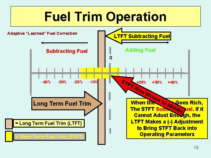
Fuel Trim Operation Adaptive “Learned” Fuel Correction LTFT Subtracting Fuel Adding Fuel Subtracting Fuel 0 -40% -30% -20% -10% Long Term Fuel Trim = Long Term Fuel Trim (LTFT) = Short Term Fuel Trim (STFT) ST +10% FT +20% No w +30% +40% Mo ve st oand When Shortthe Term Engine Goes Term Rich, Mi Long dd Operates The Fuel STFT Trim. Subtracts Usually le Fuel. If it Cannot Within. Adust the 0 Enough, – 10% (+/-) the LTFT Range, Makes When a (-) There Adjustment are No to Engine Bring STFT Performance Back into Operating Problems. Parameters 13
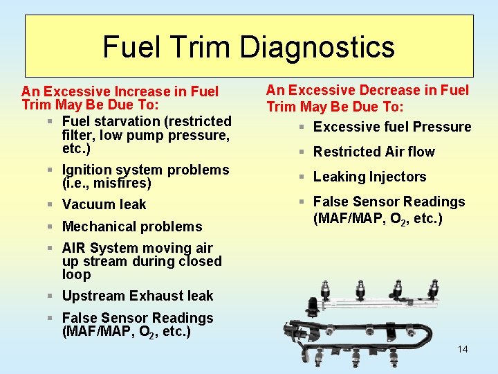
Fuel Trim Diagnostics An Excessive Increase in Fuel Trim May Be Due To: § Fuel starvation (restricted filter, low pump pressure, etc. ) An Excessive Decrease in Fuel Trim May Be Due To: § Excessive fuel Pressure § Restricted Air flow § Ignition system problems (i. e. , misfires) § Leaking Injectors § Vacuum leak § False Sensor Readings (MAF/MAP, O 2, etc. ) § Mechanical problems § AIR System moving air up stream during closed loop § Upstream Exhaust leak § False Sensor Readings (MAF/MAP, O 2, etc. ) 14
Sensor/PCM Interaction – Look Up Tables So how does the PCM make the decision on how to adjust the fuel, ignition timing, and when to turn on/off the actuators? The PCM is programmed from the factory with a series of mathematical algorithmic “look up tables. ” These look up tables are similar to the multiplication tables you learned in grade school, only much more evolved. 15
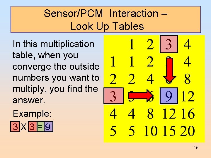
Sensor/PCM Interaction – Look Up Tables In this multiplication table, when you converge the outside numbers you want to multiply, you find the answer. Example: 3 X 3=9 16
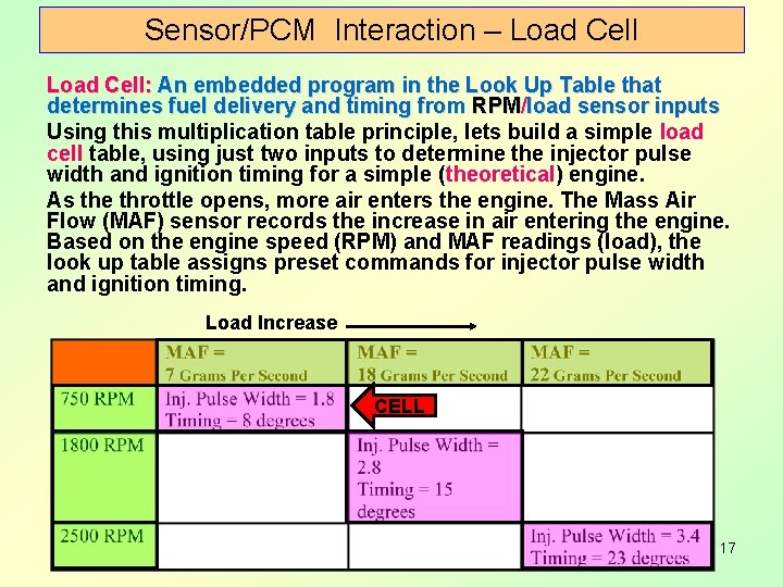
Sensor/PCM Interaction – Load Cell: An embedded program in the Look Up Table that determines fuel delivery and timing from RPM/load sensor inputs Using this multiplication table principle, lets build a simple load cell table, using just two inputs to determine the injector pulse width and ignition timing for a simple (theoretical) engine. As the throttle opens, more air enters the engine. The Mass Air Flow (MAF) sensor records the increase in air entering the engine. Based on the engine speed (RPM) and MAF readings (load), the look up table assigns preset commands for injector pulse width and ignition timing. Load Increase CELL 17
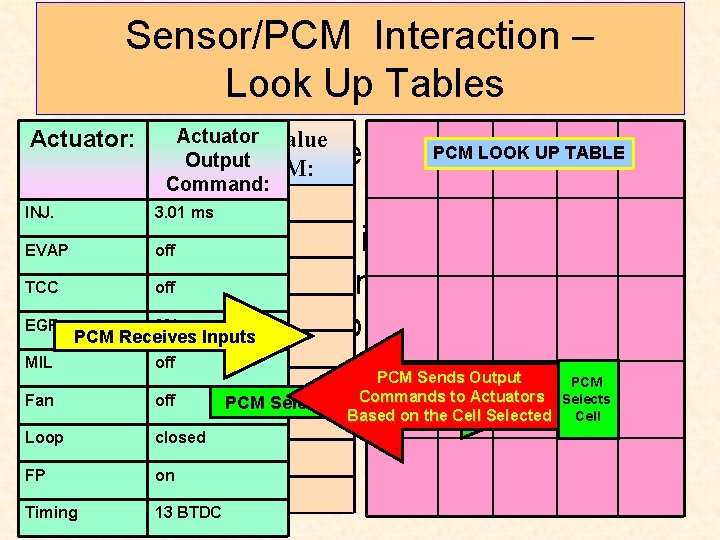
Sensor/PCM Interaction – Look Up Tables Sensor: Actuator: Actuator Input Value Output To PCM: Command: PCMsensor LOOK UP TABLE Of course, there are many ECT 0. 5 volts inputs that the PCM receives. The INJ. 3. 01 ms IAT 2. 5 volts PCM, based on the inputs it receives, EVAP off MAP 1. 0 volts TCC off has to find a matching cell (as close as TPS 0. 45 volts EGR 0% in the ‘Look Up Table. ” The possible) PCM Receives Inputs RPM 750 MIL off PCM issues (based PCM Sends Output HO 2 S. 1 -. 9 voltsoutput commands Commands to Actuators Fan off PCM Selects Closest Cell Match the Cell Selectedthe VSS 0 mph on the selected cell)Based toonoperate Loop closed B+vehicle. 14. 0 volts FP on PCM Selects Cell IAC Timing 25% 13 BTDC 18
Sensor/PCM Interaction – Adaptive Strategy Have you ever heard of this situation before? A technician diagnoses a bad throttle position sensor (shows 2 volts at idle) as the reason for high engine idle and engine performance/emission problems. He installs a new sensor, but the vehicle still runs poorly – why? Answer: The technician did not reset the PCM’s adaptive strategy. 19
Sensor/PCM Interaction – Adaptive Strategy An “Adaptive Strategy” is programmed into a PCM’s “Keep Alive Memory” (KAM) to allow the computer to adapt to deteriorating component conditions (i. e. , sensors, actuators, worn parts, etc. ) and a driver’s driving habits. This programmed strategy allows the PCM to adapt (learn) to use abnormal inputs, and still allow the vehicle to operate within a normal vehicle performance range (within reason). The KAM will maintain this “learned” strategy as long as it is supplied battery voltage. 20
Sensor/PCM Interaction – Adaptive Strategy In our scenario with the bad TPS, the technician, after completing the TPS repairs, did not clear the old TPS (adaptive strategy) information from the KAM (using the scan tool or disconnecting the battery). The PCM was still using the stored (erroneous) information it learned (adapted) from the old defective part (2 volts at idle) to run the system. This is why the vehicle still performed poorly after the repair. 21
Sensor/PCM Interaction – Adaptive Strategy Eventually, the PCM would have learned (adapted) to the new TPS input values (after a series of drive cycles), and returned to normal operation. By not resetting the PCM adaptive strategy, the customer would be upset when the vehicle was returned to them as having been “repaired, ” but still ran poorly. Telling the customer to “just drive the car and it will get better” probably won’t set too well with your customer. 22
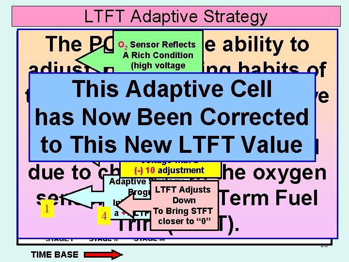
LTFT Adaptive Strategy O Sensor Reflects The PCM has the ability to A Rich Condition (high voltage adjust to the driving habits of Signal) 2 This Adaptive Cell we the driver. In this scenario, has Been Corrected will Now see how the. STFT Long term is Now 3 STFT Reacts Within 5% to the Sensor to This Value Fuel Trim. New (LTFT) is adjusted 5 High OLTFT Voltage with a (-) 10 adjustment due to changes in the oxygen Adaptive Strategy LTFT Adjusts Program Down sensor and Short Term Fuel Initially Assigns 1 To Bring STFT 4 a +7 LTFT Value to “ 0” Trimcloser (STFT). 2 2 23 TIME BASE
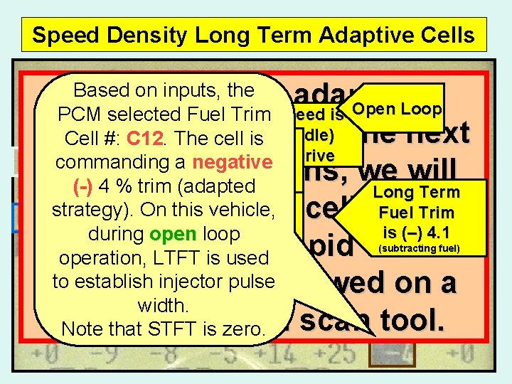
Speed Density Long Term Adaptive Cells Based on inputs, the Let’s see this adaptive Engine PCM selected Fuel Trim Speed is Open Loop 795 is RPM (Idle) strategy In the next Cell #: C 12. in Theaction. cell Injector Trans in Drive Pulse Width commanding a negative 5 (-) scan tool screens, we will is 2. 8 m. S 4 % trim (adapted Long Term Short Term strategy). On this vehicle, see the fuel trim for. Trim a Fuel Trim cells Fuel is (–) 4. 1 during open loop Is at 0. 0 (subtractinga fuel) 2000 Dodge Intrepid with operation, LTFT is used to establish injector pulse 3. 5 L engine, as viewed on a width. Chrysler Note that STFTDRB is zero. II scan tool.
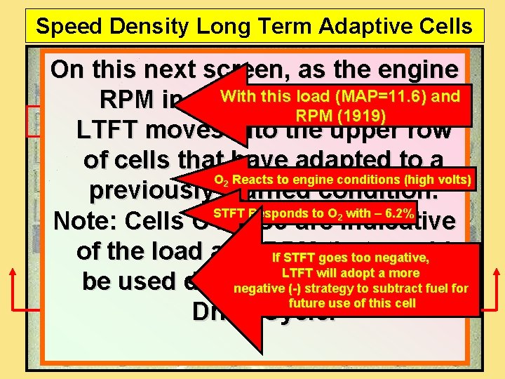
Speed Density Long Term Adaptive Cells On this next screen, as the engine With thisabove load (MAP=11. 6) RPM increases 1900, and RPM (1919) LTFT moves into the upper row of cells that have adapted to a O Reacts to engine conditions (high volts) previously learned condition. STFT Responds to O with – 6. 2% Note: Cells C 4 & C 5 are indicative of the load and RPM that would If STFT goes too negative, LTFT will adopt a more The PCM cell C 5 be used during an(-)chose ASM negative strategy totest subtractor fuel for future use of this cell Drive Cycle. 2 2
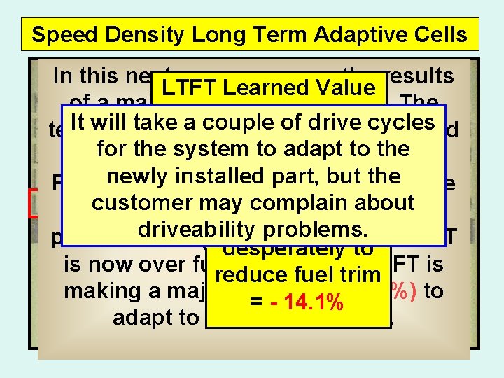
Speed Density Long Term Adaptive Cells In this next screen, we see the results LTFT Learned Value of a major fuel trim correction. The from Badof Part = cycles It will take a couple drive technician installed a new part, but did + 12. 7% for the system to adapt to the. The not reset the adaptive strategy. installed part, but from the PCM newly is using a learned value mayincomplain aboutthe badcustomer part (+13%) cell C 8. Since STFT Is trying driveability problems. problem has been corrected, the LTFT desperately to is now over fueling, and the STFT is reduce fuel trim making a major correction (-14%) to = - 14. 1% adapt to the new situation.
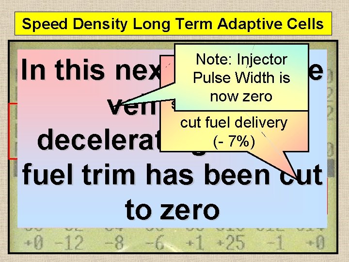
Speed Density Long Term Adaptive Cells Note: Injector With the throttle Pulse Width is closed, the PCM now zero selects cell C 15 to In this next sceen, the vehicle is cut fuel delivery 7%) all decelerating (-and fuel trim has been cut to zero
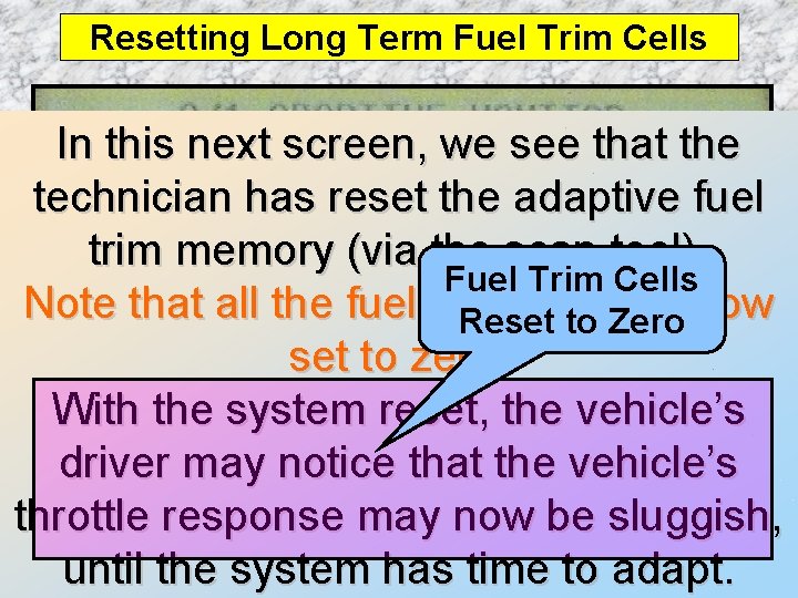
Resetting Long Term Fuel Trim Cells In this next screen, we see that the technician has reset the adaptive fuel trim memory (via the scan tool). Fuel Trim Cells Note that all the fuel trim cells are now Reset to Zero set to zero. With the system reset, the vehicle’s driver may notice that the vehicle’s throttle response may now be sluggish, until the system has time to adapt.
- Review - As you can see, if sensor(s) input (e. g. , MAF, TPS, IAT, ECT, etc. ) is incorrect, the PCM will still try to match the (erroneous) inputs it receives to the closest matching cell. Due to the bad sensor input(s), the cell selected by the PCM will not be appropriate for the actual operating conditions of the vehicle. The vehicle may now experience an emission(s) failure/driveability problem. Example: If the wrong cell was selected by the PCM (e. g. , using bad MAF info), that cell may not allow EGR activation; thus the vehicle may fail for NOx. If the correct cell were selected, the EGR would be activated, and the NOx problem would 29 not be present.
- Review - - REMEMBER • Garbage In = Garbage Out = 30

NETWORK AND “CAN” SYSTEMS 31
AUTOMOTIVE NETWORKS For many years, as vehicle manufacturers added new features to their vehicles, they had to add more sensors, actuators, and wiring to accommodate these new features. These additions added more complexity to the vehicle, and required a larger and more expensive central computer. For example, when electric cooling fans were first controlled by the OBD system, it was not uncommon for an engine to have three coolant temperature sensor/switches: one for the coolant temperature input to PCM, one for the electric cooling fan operation, and one for the coolant temperature warning light or gauge on the dash. These extra sensors/switches were redundant, and added weight (less fuel economy) to the vehicle, and added more potential for system failure (shorts, opens, etc. ). To eliminate these problems, manufacturers changed to a 32 network system.
AUTOMOTIVE NETWORKS When you use the internet, or use your ATM card at the bank or market, you are using a network system. This system shares information with other workstations (banks, internet providers, etc. ) on a common carrier system (e. g. telephone or internet system). A Local Area Network (LAN) is a network that is contained to one local area, like your home, shop, or car. Car manufacturers have been using LAN systems on cars for years. 33
AUTOMOTIVE NETWORKS The advantages to having a LAN system are: • Eliminates hard wiring of sensors/actuators to every component (e. g. PCM, warning lights, fans, etc. ), which results in lower production costs. • Eliminates redundant components and wiring, which reduces vehicle weight (better fuel economy). • Reduces potential system failures (shorts, opens, etc. ), since there is less wiring. • Information transfer is faster between component systems. 34
CONTROLLER AREA NETWORK (CAN) NO, we are not talking about this kind of Can! 35
CONTROLLER AREA NETWORK (CAN) Most vehicle manufacturers are moving to a network system called “Controller Area Network” (CAN). This system will be required on all light duty vehicles sold in California by model year (MY) 2008. The advantage of this system is that all vehicles will have a standardized communication protocol, so your scan tool will be able to communicate with this high speed network system. 36
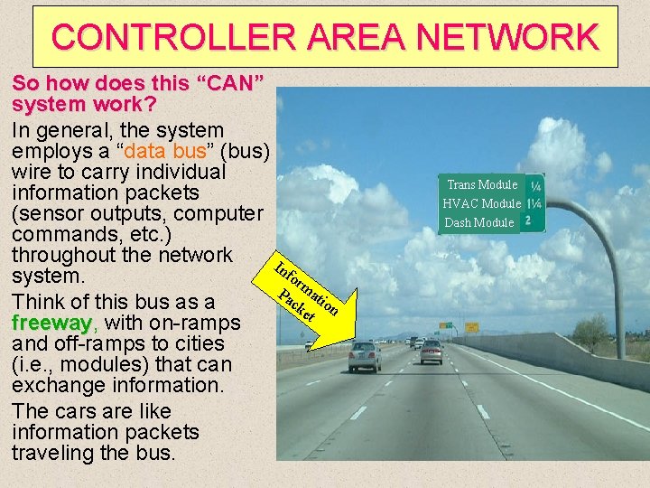
CONTROLLER AREA NETWORK So how does this “CAN” system work? In general, the system employs a “data bus” (bus) wire to carry individual information packets (sensor outputs, computer commands, etc. ) throughout the network In fo system. r Pa mati ck on Think of this bus as a et freeway, freeway with on-ramps and off-ramps to cities (i. e. , modules) that can exchange information. The cars are like information packets traveling the bus. Trans Module HVAC Module Dash Module 37
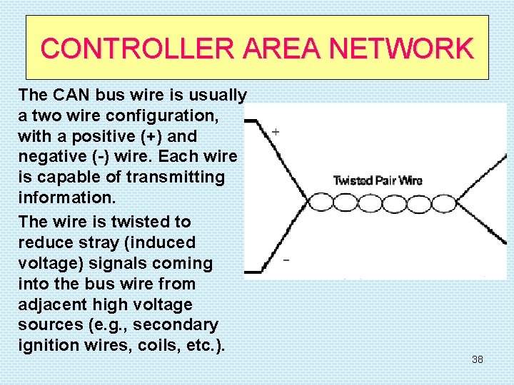
CONTROLLER AREA NETWORK The CAN bus wire is usually a two wire configuration, with a positive (+) and negative (-) wire. Each wire is capable of transmitting information. The wire is twisted to reduce stray (induced voltage) signals coming into the bus wire from adjacent high voltage sources (e. g. , secondary ignition wires, coils, etc. ). 38
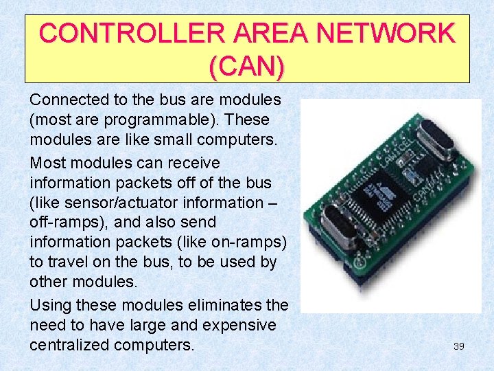
CONTROLLER AREA NETWORK (CAN) Connected to the bus are modules (most are programmable). These modules are like small computers. Most modules can receive information packets off of the bus (like sensor/actuator information – off-ramps), and also send information packets (like on-ramps) to travel on the bus, to be used by other modules. Using these modules eliminates the need to have large and expensive centralized computers. 39
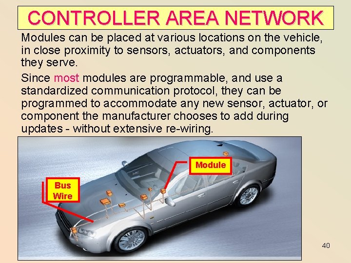
CONTROLLER AREA NETWORK Modules can be placed at various locations on the vehicle, in close proximity to sensors, actuators, and components they serve. Since most modules are programmable, and use a standardized communication protocol, they can be programmed to accommodate any new sensor, actuator, or component the manufacturer chooses to add during updates - without extensive re-wiring. Module Bus Wire 40
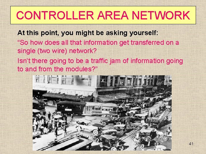
CONTROLLER AREA NETWORK At this point, you might be asking yourself: “So how does all that information get transferred on a single (two wire) network? Isn’t there going to be a traffic jam of information going to and from the modules? ” 41
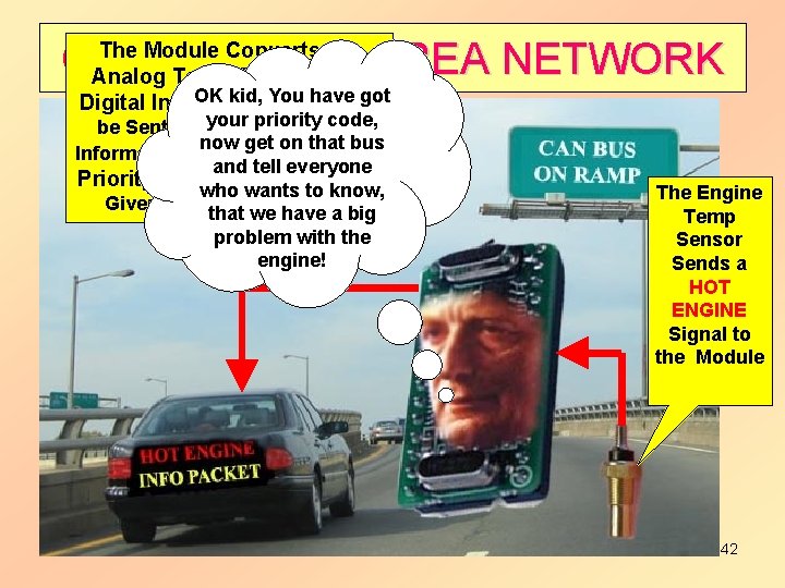
The Module Converts the CONTROLLER Analog Temp Signal into a AREA NETWORK OK kid, You have to got Digital Information Packet, priority code, be Sent Outyour on the Bus. The now get on that bus Information Packet is assigned a Each moduleandistell programmed to emit it’s data, everyone Priority Code. In this Case, it is who wants to know, The Engine using an aelectronic code. This coded data packet Given High Priority Code that we have a big Temp problem based with the on how important it is Sensor is given a priority, to Sends a the operation ofengine! the vehicle. HOT ENGINE Signal to the Module 42
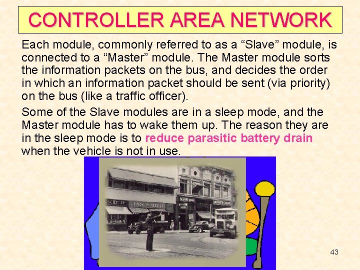
CONTROLLER AREA NETWORK Each module, commonly referred to as a “Slave” module, is connected to a “Master” module. The Master module sorts the information packets on the bus, and decides the order in which an information packet should be sent (via priority) on the bus (like a traffic officer). Some of the Slave modules are in a sleep mode, and the Master module has to wake them up. The reason they are in the sleep mode is to reduce parasitic battery drain when the vehicle is not in use. 43
CONTROLLER AREA NETWORK The Master module will wake up a Slave module for the following reasons: Ø Ø Ø Another module is requesting information that the sleeping module can provide (e. g. , sensor/actuator information). Another module is sending information that the sleeping module needs (e. g. , actuator commands, etc. ). The Master module determined that more computing ability is needed to operate the vehicle, so it uses the computing resources of the sleeping module to assist in carrying out difficult computing functions (an additional computer resource). 44
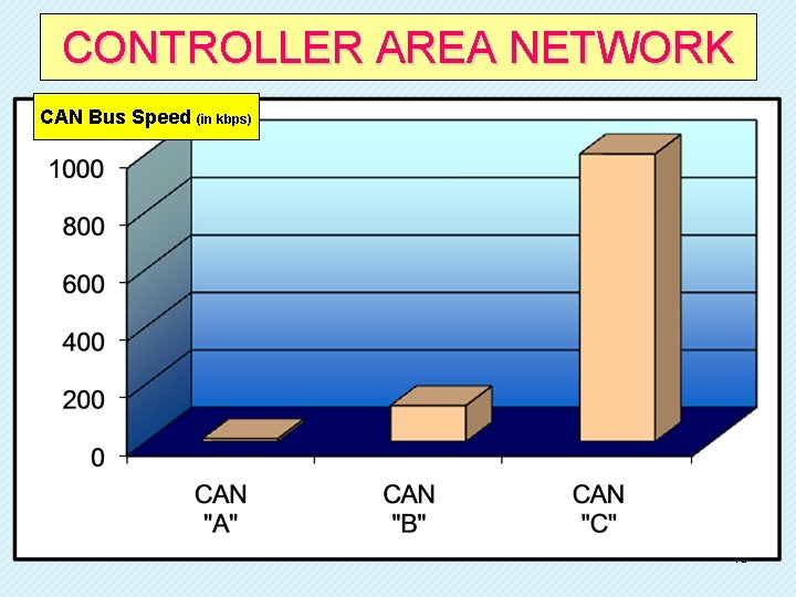
CONTROLLER AREA NETWORK CAN Busare Speed (in kbps) There three classes of CAN. The classes are defined by the Society of Automotive Engineers (SAE) based on data speed of the bus; measured in kilobits per second (kbps): kbps Ø CAN “A” – Has very slow data transference speed, at about 10 kbps. This class was used on early vehicle systems, but is seldom used today. Ø CAN “B” – Has medium data transference speed at about 83 - 125 kbps. This class is used for vehicle systems that don’t require exceptional data transference speed (e. g. , body control module, HVAC module, etc. ). Ø CAN “C” – Has high data transference speed, at about 500 1000 kbps. This class is used primarily on powertrain and chassis systems that require high data speed (e. g. , electronically operated: throttle, steering, brakes, etc. ). Usually, this system only has three modules (e. g. , PCM, TCM, ABS). 45
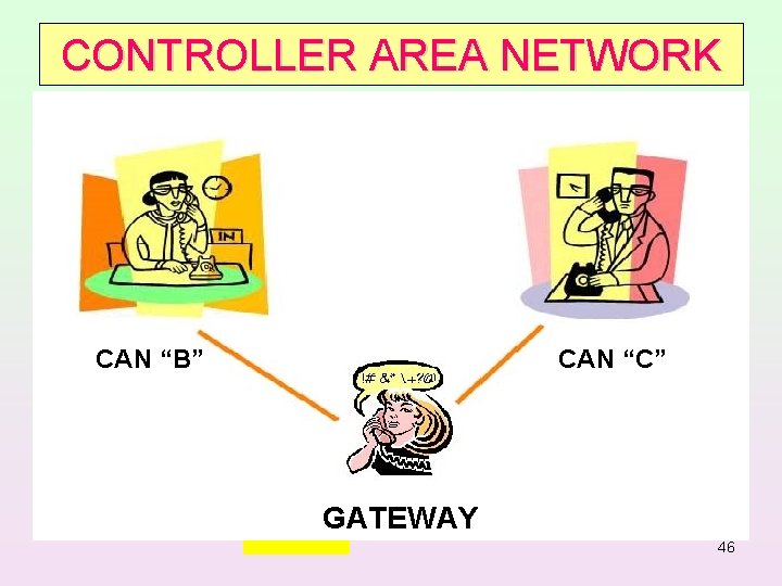
CONTROLLER AREA NETWORK Most vehicles today employ the use of both CAN “B” and “C” bus systems to operate the vehicle. To allow these two bus systems, of vastly different data rate speeds, to share information with each other, the CAN system employs a “Gateway” module. “B” acts as an interface between the CAN “C” The CAN Gateway different buses (like an interpreter), which allows them to share information. Usually, the Master module and the Gateway module are incorporated into one unit. GATEWAY 46
CONTROLLER AREA NETWORK System Failure: If one of the two wires on the CAN “B” bus has a short/open, then the following may happen: Ø The system will still operate, but may not function as designed. The system may be slow in operation. Ø Depending on where the short/open is located, some part of the system may not operate at all. Ø If a sensor input from a defective section cannot get a signal to a good module needing that sensor input, then that good module may not operate as designed (e. g. , bad module attached to speed sensor may cause problems with PCM outputs). 47
CONTROLLER AREA NETWORK System Failure (con’t): ØIn a severe CAN “B” bus wire failure (both wires open/grounded), multiple system failures can occur. ØImproper dashboard warning light operations may occur. ØMIL will be illuminated. 48
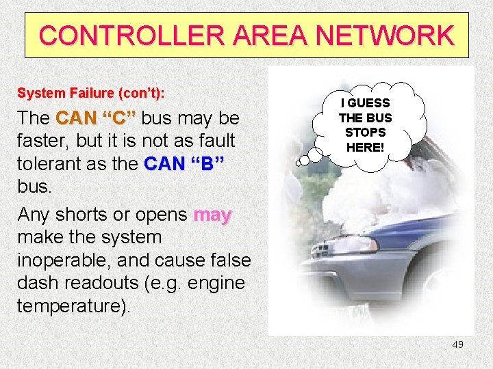
CONTROLLER AREA NETWORK System Failure (con’t): The CAN “C” bus may be faster, but it is not as fault tolerant as the CAN “B” bus. Any shorts or opens may make the system inoperable, and cause false dash readouts (e. g. engine temperature). I GUESS THE BUS STOPS HERE! 49
CONTROLLER AREA NETWORK System Failure (con’t): The Gateway/Master module is constantly polling all the modules to check their readiness status, and their ability to transmit/receive data. If a module is operating incorrectly, the Gateway/Master module will advise all the other modules that this module is inoperative, and to ignore it. The Gateway/Master module will continue to poll that problem module to see if a correction was made while the vehicle is in operation. If the module returns to operational status, the Gateway/Master module will inform all the other modules that this module is now operational, and to accept that module’s information. If a module continues to be faulty, or the bus wire is faulty, a “U” Code (DTC) will be generated. 50
CONTROLLER AREA NETWORK NOTE: For you to diagnose/repair a CAN vehicle, you need to have access to the appropriate diagnostic manuals, TSBs, and have a CAN compatible scan tool. Most scan tool manufacturers already have CAN compatible tools and upgrades available. A Smog Check Test and Repair station must have a CAN compatible scan tool to inspect CAN vehicles. 51
CAN CASE STUDY: To illustrate how the CAN system is a fully integrated/interactive system, here are two true stories: One evening, a fleet maintenance technician changed a defective license plate bulb on a fully functional 2005 Ford truck. The next morning the truck would not start! What happened? It appears that the bulb he replaced was of a higher amperage rating than the original bulb. The multiplex system sensed the higher amperage draw during a system self test at start up, and shut down the fuel pump relay. The PCM did this so the bus system and components would not be damaged by the bulb’s high current draw while the vehicle was operational. This was not an easy one to figure out, since the repair technician was not aware that the bulb had been replaced the night before! 52
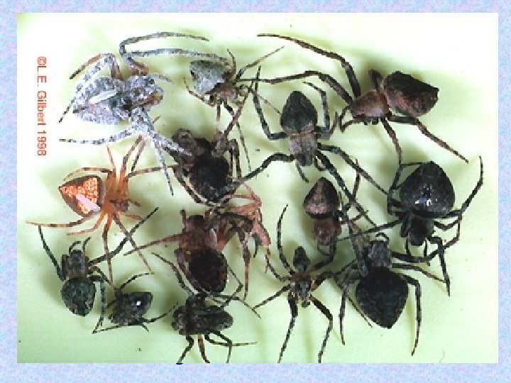
CAN CASE STUDY (con’t): CAN Arachnophobia: A 2004 Ford comes into the shop with the following complaints: The vehicle periodically slows down to a maximum speed of 25 -35 mph for no reason (even at full throttle); and by the way, the “door ajar” light comes on occasionally, even though all doors are closed tight. What’s the problem? After a lot of head scratching, it was found that baby spiders had made a nest in the rear door switch, causing an intermittent poor circuit problem (door ajar). The CAN system thought the door was open going down the highway; so to protect the passenger from an unscheduled bailout at fatal speeds, the PCM limited the vehicle to 35 mph. Who would of seen this one coming? Keep the 53 door closed during an ASM test!
OBD II EVAPORATIVE EMISSION CONTROL SYSTEMS

OBD II EVAPORATIVE Video Low Pressure Evap Testing
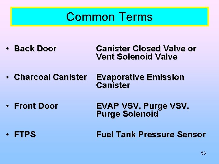
Common Terms • Back Door Canister Closed Valve or Vent Solenoid Valve • Charcoal Canister Evaporative Emission Canister • Front Door EVAP VSV, Purge Solenoid • FTPS Fuel Tank Pressure Sensor 56
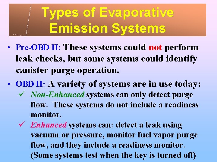
Types of Evaporative Emission Systems • Pre-OBD II: These systems could not perform leak checks, but some systems could identify canister purge operation. • OBD II: A variety of systems are in use today: ü Non-Enhanced systems can only detect purge flow. These systems do not include a readiness monitor. ü Enhanced systems can: detect a leak using vacuum or pressure, monitor fuel vapor purge flow, and they include a readiness monitor. (Some systems test when the key is turned off)
58
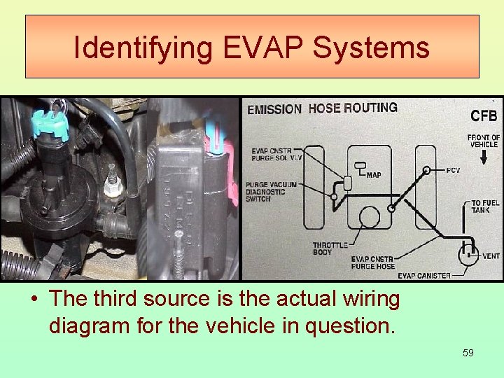
Identifying EVAP Systems • The first source of information is the under -the-hood emission decal. – Keep in mind that the decal only shows components located in the engine compartment. • The second source is the component locator manual for the vehicle in question. • The third source is the actual wiring diagram for the vehicle in question. 59
OBD II Non-Enhanced Evaporative Control System Operation 60
Early OBD II Evaporative Emission Control Systems • Early OBD II systems did not require Enhanced Evaporative Emission Controls. – Non-Enhanced systems were in limited use from 1996 to 2000. – This means the system could not detect a leak; a loose or missing gas cap would not be identified by this system – It can only detect vapor flow or purge vacuum by using a switch or fuel trim. • This system can be identified quickly by using the underhood vacuum diagram. The diagram will indicate just a purge solenoid with a vapor or purge switch (no 61 vent solenoid valve).
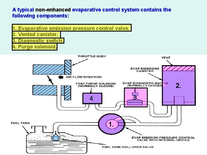
A typical non-enhanced evaporative control system contains the following components: 1. Evaporative emission pressure control valve. 2. Vented canister. 3. Diagnostic switch. 4. Purge solenoid. 2. 3. 4. 1. 62
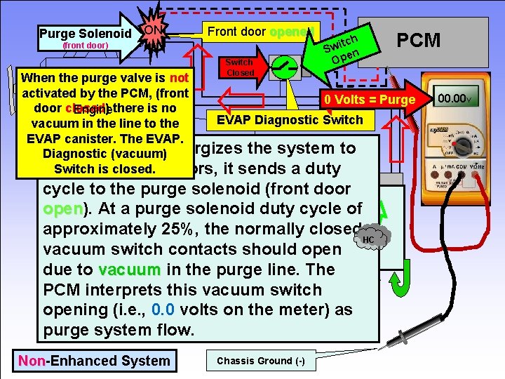
Purge Solenoid ON Frontdooropened closed (front door) Switch Closed itch w S n Ope PCM When the purge valve is not activated by the PCM, (front 0 Volts = Purge door closed) closed Enginethere is no EVAP Diagnostic Switch vacuum in the line to the EVAP canister. The EVAP. When the(vacuum) PCM energizes the system to Diagnostic Switchthe is closed. purge fuel vapors, it sends a duty 00. 00 V cycle to the purge solenoid (front door open). open At a purge solenoid duty cycle of approximately 25%, the normally closed HC vacuum switch contacts should open due to vacuum in the purge line. The PCM interprets this vacuum switch opening (i. e. , 0. 0 volts on the meter) as purge system flow. Non-Enhanced System Non Chassis Ground (-) 63
OBD II ENHANCED EVAPORATIVE CONTROL SYSTEM OPERATION 64
Overview of Enhanced Evaporative Emission Leak Detection • Beginning in 1998, Enhanced EVAP systems appeared, that were capable of detecting a leak as small as. 040 of an inch (. 040”). • By 2000, all vehicles were required to phase in an Enhanced EVAP system capable of detecting a leak as small as. 020”. • Both systems include an EVAP Readiness Monitor that runs once per “Trip” when the Enable Criteria is met. • Some manufacturers included a diagnostic “Service Bay” test in their scan tools to assist with the verification of a repair.
Enhanced Evaporative Emission Leak Detection Systems ü Vacuum Decay: Uses engine vacuum to create a vacuum in the fuel tank, canister, and lines to identify leaks. ü Fuel Tank Pressure/Canister Vacuum: Using engine vacuum, this system can isolate the fuel tank from the Charcoal Canister (via a solenoid valve) to pinpoint a leak. ü Leak Detection Pump: Uses flow from a pump to pressurize the system to check for leaks. ü Engine Off Natural Vacuum Leak: Uses the principle of gas/fluid expansion/contraction in a closed container. As temperature changes, the resultant increase/decrease in 66 pressure or vacuum will identify if leaks are present.
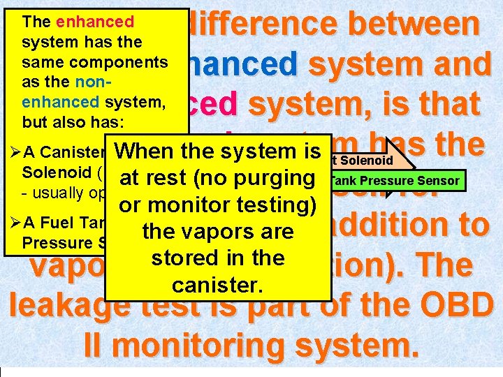
The enhanced The main difference between PCM system has the same components the non-enhanced system and Front Door Closed as the nonenhanced system, the enhanced system, is that Back Door Open but also has: enhanced system has the Øthe A Canister Vent When the system is Solenoid (back door at rest (no purging ability to check itself for - usually open) or monitor testing) Ø A Fuel Tank leakage (in addition to system the vapors are Pressure Sensor stored in the vapor purge operation). The canister. leakage test is part of the OBD II monitoring system. Vent Solenoid (back Fuel Tankdoor) Pressure Sensor E II II II F FTP 67
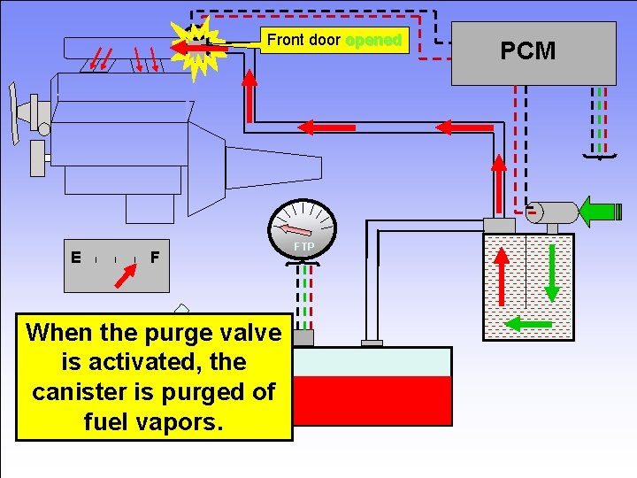
Front door opened E I I I F PCM FTP When the purge valve is activated, the canister is purged of fuel vapors. 68
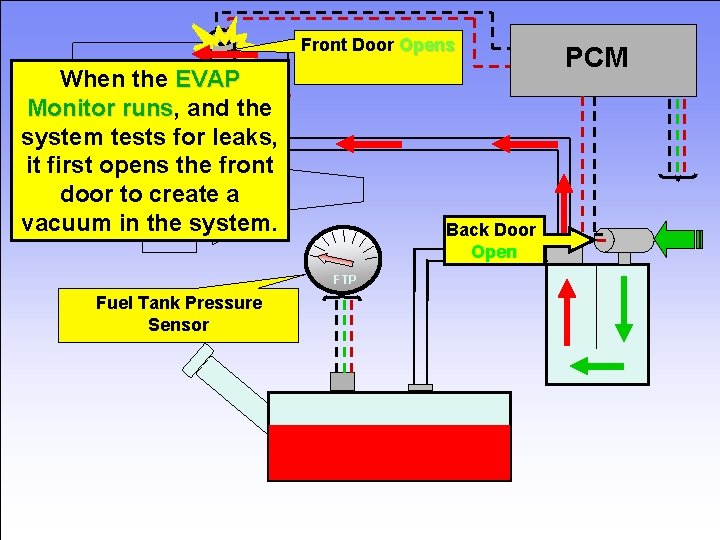
Front Door Opens When the EVAP Monitor runs, runs and the system tests for leaks, it first opens the front door to create a vacuum in the system. PCM Back Door Open FTP Fuel Tank Pressure Sensor 69
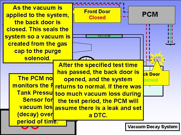
As the vacuum is Front Door Open Front PCM applied to the system, Closed the back door is closed. This seals the VACUUM system so a vacuum is created from the gas cap to the purge solenoid. After the specified test time FTP has passed, the back door is. Back Door The. Tank PCM now Sensor Fuel Pressure Closed opened, and the system Opened monitors the Fuel returns to normal. If there was Tank too much vacuum loss during Once. Pressure a specified Sensorreading for theistest period, vacuum VACUUM the PCM will vacuum loss there is a leak and set obtained, the assume PCM (decay) a DTC. closes theover fronta door. period of time. 06 05 04 03 02 01 70 Vacuum Decay System
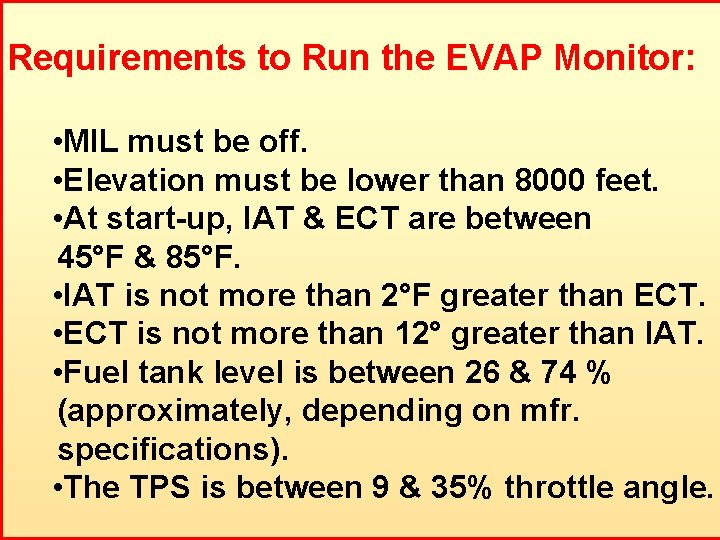
PCM Requirements to Run the EVAP Monitor: • MIL must be off. What does thethan PCM • Elevation must be lower 8000 feet. ALL the criteria needs • At. First, start-up, IAT & ECT are between have to see before it can 45°F 85°F. to&run be met before the PCM the EVAP • IAT is not more than 2°FMonitor greater than ECT. can run the EVAP monitor. • ECT is not more and than 12° greater than IAT. does that mean? • Fuel What tank level is between 26 & 74 % test the system? (approximately, depending on mfr. specifications). • The TPS is between 9 & 35% throttle angle. 71

A CLOSER LOOK AT COMPONENT PARTS
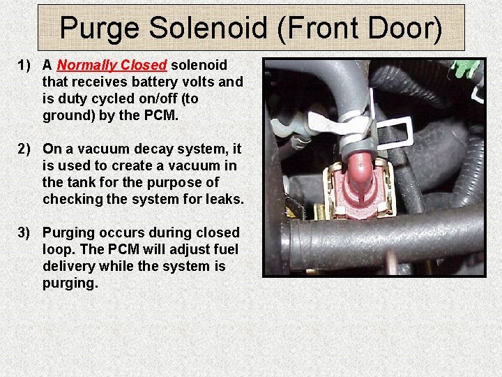
Purge Solenoid (Front Door) 1) A Normally Closed solenoid that receives battery volts and is duty cycled on/off (to ground) by the PCM. 2) On a vacuum decay system, it is used to create a vacuum in the tank for the purpose of checking the system for leaks. 3) Purging occurs during closed loop. The PCM will adjust fuel delivery while the system is purging.
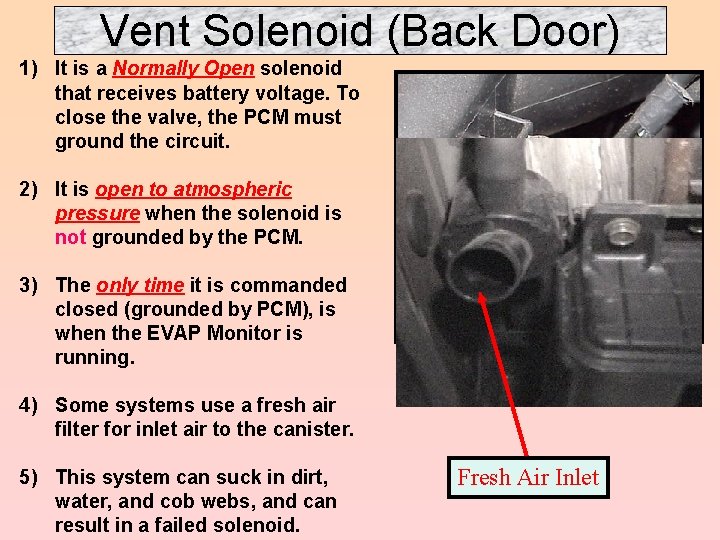
Vent Solenoid (Back Door) 1) It is a Normally Open solenoid that receives battery voltage. To close the valve, the PCM must ground the circuit. 2) It is open to atmospheric pressure when the solenoid is not grounded by the PCM. 3) The only time it is commanded closed (grounded by PCM), is when the EVAP Monitor is running. 4) Some systems use a fresh air filter for inlet air to the canister. 5) This system can suck in dirt, water, and cob webs, and can result in a failed solenoid. Fresh Air Inlet
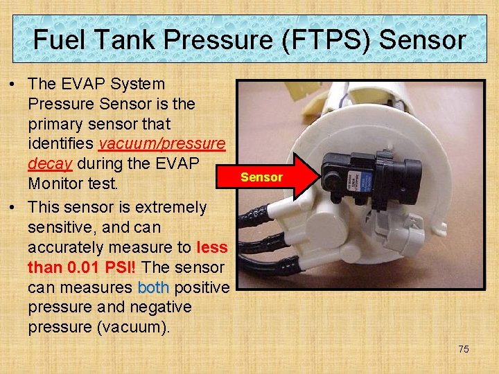
Fuel Tank Pressure (FTPS) Sensor • The EVAP System Pressure Sensor is the primary sensor that identifies vacuum/pressure decay during the EVAP Monitor test. • This sensor is extremely sensitive, and can accurately measure to less than 0. 01 PSI! The sensor can measures both positive pressure and negative pressure (vacuum). Sensor 75
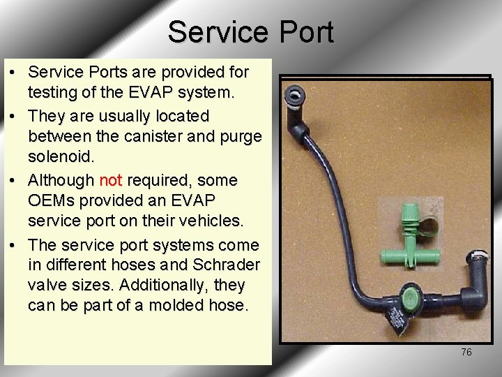
Service Port • Service Ports are provided for testing of the EVAP system. • They are usually located between the canister and purge solenoid. • Although not required, some OEMs provided an EVAP service port on their vehicles. • The service port systems come in different hoses and Schrader valve sizes. Additionally, they can be part of a molded hose. 76
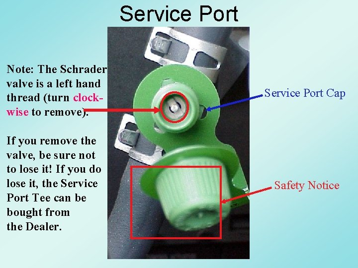
Service Port Note: The Schrader valve is a left hand thread (turn clockwise to remove). Service Port Cap If you remove the valve, be sure not to lose it! If you do lose it, the Service Port Tee can be bought from the Dealer. Safety Notice
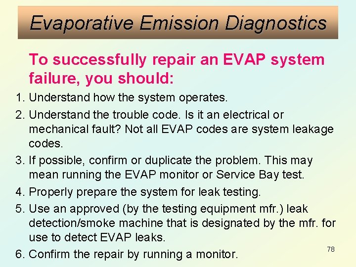
Evaporative Emission Diagnostics To successfully repair an EVAP system failure, you should: 1. Understand how the system operates. 2. Understand the trouble code. Is it an electrical or mechanical fault? Not all EVAP codes are system leakage codes. 3. If possible, confirm or duplicate the problem. This may mean running the EVAP monitor or Service Bay test. 4. Properly prepare the system for leak testing. 5. Use an approved (by the testing equipment mfr. ) leak detection/smoke machine that is designated by the mfr. for use to detect EVAP leaks. 78 6. Confirm the repair by running a monitor.
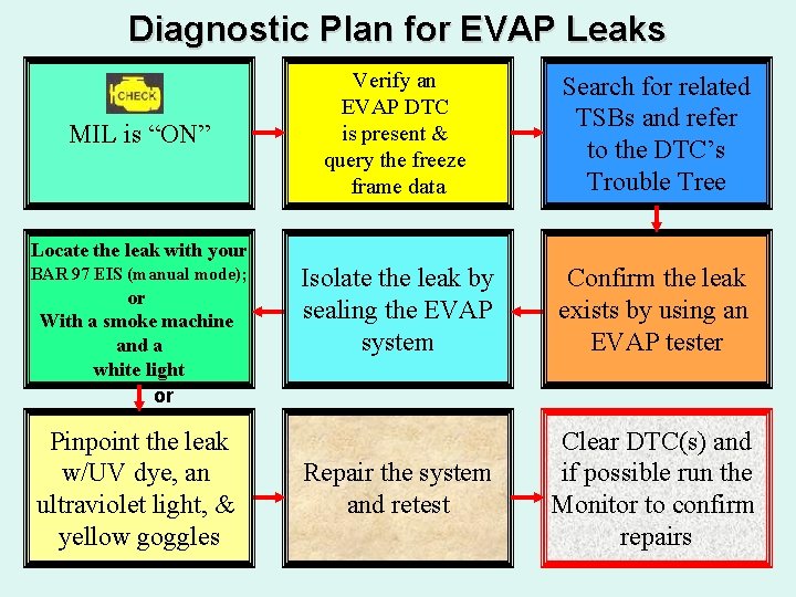
Diagnostic Plan for EVAP Leaks MIL is “ON” Verify an EVAP DTC is present & query the freeze frame data Search for related TSBs and refer to the DTC’s Trouble Tree Isolate the leak by sealing the EVAP system Confirm the leak exists by using an EVAP tester Repair the system and retest Clear DTC(s) and if possible run the Monitor to confirm repairs Locate the leak with your BAR 97 EIS (manual mode); or With a smoke machine and a white light or Pinpoint the leak w/UV dye, an ultraviolet light, & yellow goggles 79
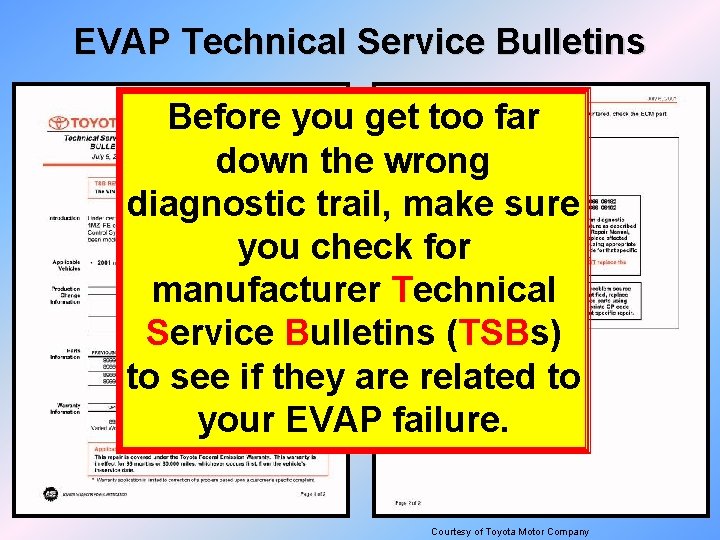
EVAP Technical Service Bulletins Before you get too far down the wrong diagnostic trail, make sure you check for manufacturer Technical Service Bulletins (TSBs) to see if they are related to your EVAP failure. 80 Courtesy of Toyota Motor Company
Evaporative Emission Diagnostics Getting Started: ü Look for loosely fitting hoses or clamps, cracked hoses, or any signs the system could have been damaged in an accident. ü Verify all electrical connections: q Purge Solenoid q Bypass Valve q Vent Solenoid or Canister Closed Valve q Fuel Tank Pressure Sensor ü Verify the operation of the Purge and Vent solenoids by activating them using bi-directional testing, if the vehicle is so equipped. Listen and feel for correct operation as each solenoid is turned ON/OFF. Repeat this test multiple times to exercise the 81 solenoid(s).

82
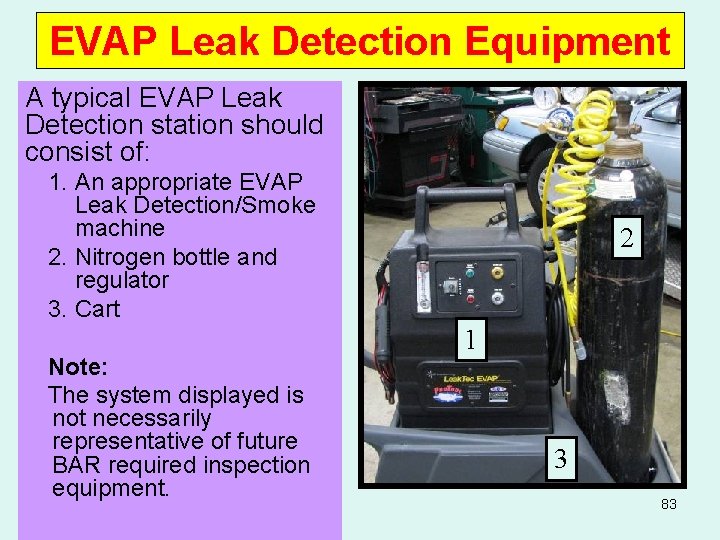
EVAP Leak Detection Equipment A typical EVAP Leak Detection station should consist of: 1. An appropriate EVAP Leak Detection/Smoke machine 2. Nitrogen bottle and regulator 3. Cart Note: The system displayed is not necessarily representative of future BAR required inspection equipment. 2 1 3 83
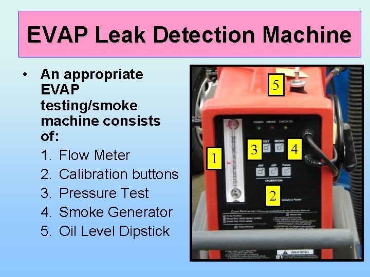
EVAP Leak Detection Machine • An appropriate EVAP testing/smoke machine consists of: 1. Flow Meter 2. Calibration buttons 3. Pressure Test 4. Smoke Generator 5. Oil Level Dipstick 5 1 4 3 2 84
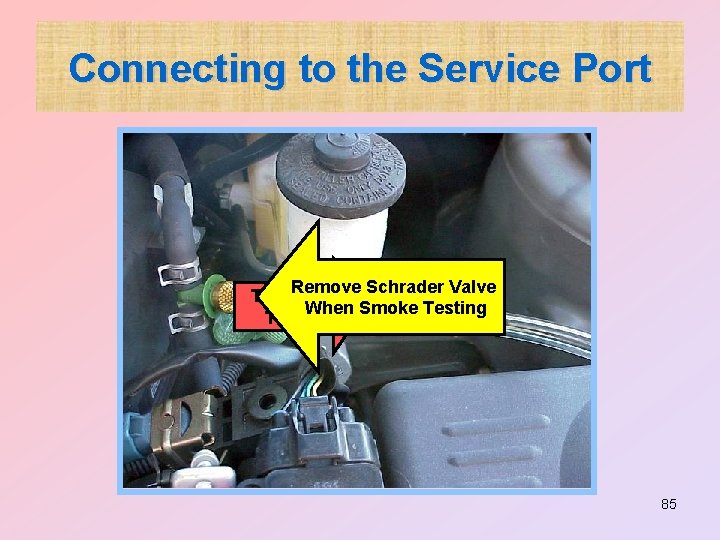
Connecting to the Service Port Remove Schrader Valve To EVAP When Smoke Testing Tester 85
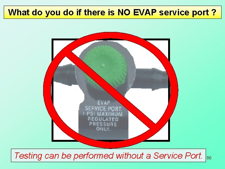
What do you do if there is NO EVAP service port ? Testing can be performed without a Service Port. 86
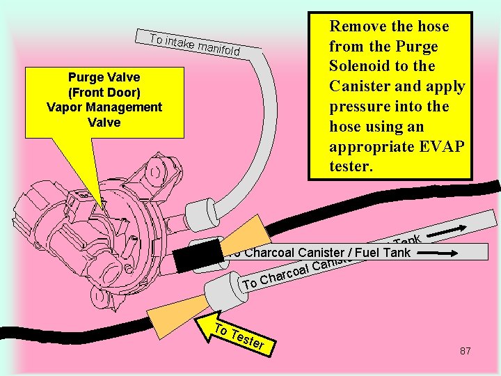
To intak e manif old Purge Valve (Front Door) Vapor Management Valve Remove the hose from the Purge Solenoid to the Canister and apply pressure into the hose using an appropriate EVAP tester. ank T l e To Charcoal Canisterte/ r. Fuel / Fu Tank anis C l a arco h C To To Tes ter 87
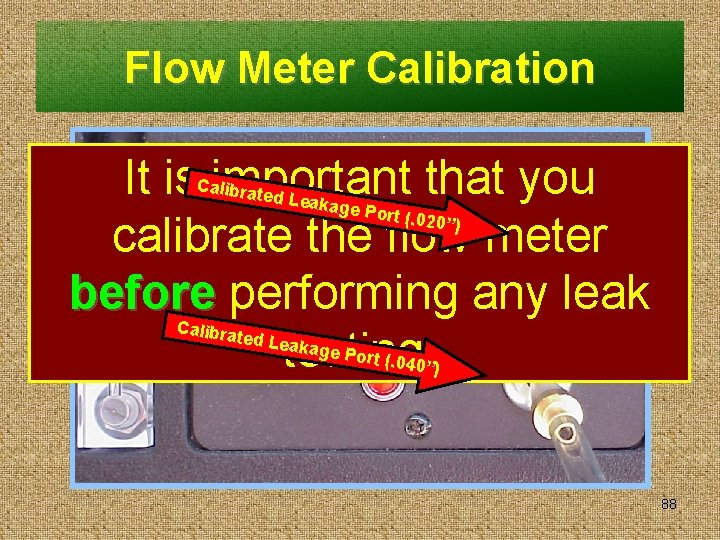
Flow Meter Calibration It is important that you calibrate the flow meter before performing any leak testing. Calibra ted Lea kage P ort (. 02 ort (. 04 0”) 88
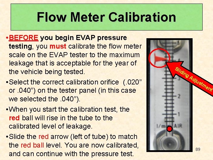
Flow Meter Calibration • BEFORE you begin EVAP pressure testing, testing you must calibrate the flow meter scale on the EVAP tester to the maximum leakage that is acceptable for the year of the vehicle being tested. • Select the correct calibration orifice (. 020” or. 040”) on the tester panel (in this case we selected the. 040”). • When you start the calibration test, the red ball will rise in the tube to the calibrated level of leakage. • Slide the red arrow (left of tube) to match the red ball level. You are now calibrated, and can continue with the pressure test. Sli d ing Ad ju stm en t 89
Closing the Vent Solenoid (Back Door) Prior to pressure testing the EVAP system, you must seal the system by closing the vent solenoid valve. To close the valve you can: • Use Mode 8 of a Generic scan tool. • Use Functional or Output Tests found on the OEM side of an aftermarket scan tool. 90
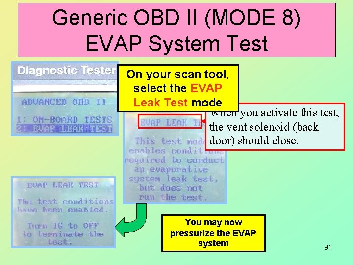
Generic OBD II (MODE 8) EVAP System Test On your scan tool, select the EVAP Leak Test mode When you activate this test, the vent solenoid (back door) should close. You may now pressurize the EVAP system 91
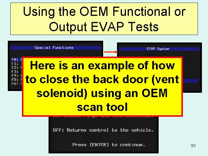
Using the OEM Functional or Output EVAP Tests Here is an example of how to close the back door (vent solenoid) using an OEM scan tool 92
SCAN TOOL CAN’T CLOSE THE BACK DOOR? First of all, it’s NOT a fault of the scan tool. Some systems are not designed to do this task! 93
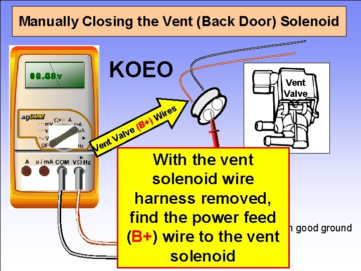
Manually Closing the Vent (Back Door) Solenoid KOEO 00. 00 v 12. 43 v Vent Valve s e nt Ve lv Va ) + B ( re Wi With the vent solenoid wire harness removed, find the power feed Put to known good ground (B+) wire to the vent 94 solenoid
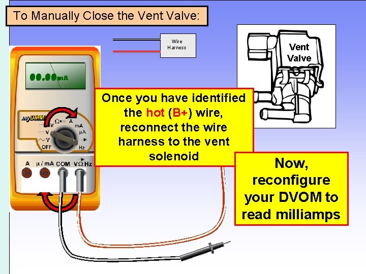
To Manually Close the Vent Valve: Wire Harness Vent Valve 00. 00 vm. A Once you have identified the hot (B+) wire, reconnect the wire harness to the vent solenoid Now, reconfigure your DVOM to read milliamps 95
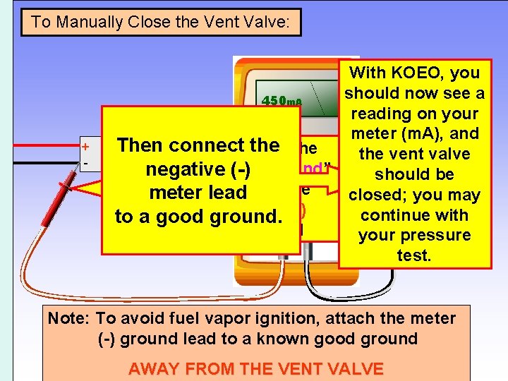
To Manually Close the Vent Valve: + - With KOEO, you should now see a 450 m. A reading on your - (m. A), and + meter Then connect the Back probe the vent valve harness negative (-) “ground” should beof Battery wire with the meter lead closed; vehicle you may positive (+) continue with being tested. to a good ground. meter lead your pressure test. Note: To avoid fuel vapor ignition, attach the meter (-) ground lead to a known good ground AWAY FROM THE VENT VALVE 96
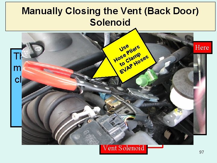
Manually Closing the Vent (Back Door) Solenoid e rs. Air Filter – Clamp Here Vent Valve Hose Us lito e The system can be manually closed by clamping the fresh hose before or after the vent solenoid. e P mp s s Ho Cla ose to P H A EV Vent Solenoid 97
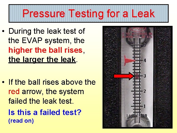
Pressure Testing for a Leak • During the leak test of the EVAP system, the higher the ball rises, rises the larger the leak. • If the ball rises above the red arrow, the system failed the leak test. Is this a failed test? (read on) 98
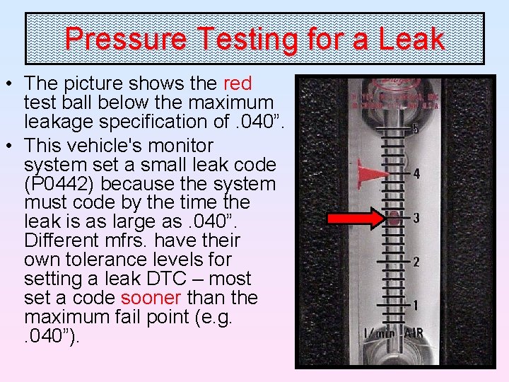
Pressure Testing for a Leak • The picture shows the red test ball below the maximum leakage specification of. 040”. • This vehicle's monitor system set a small leak code (P 0442) because the system must code by the time the leak is as large as. 040”. Different mfrs. have their own tolerance levels for setting a leak DTC – most set a code sooner than the maximum fail point (e. g. . 040”). 99
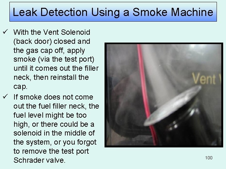
Leak Detection Using a Smoke Machine ü With the Vent Solenoid (back door) closed and the gas cap off, apply smoke (via the test port) until it comes out the filler neck, then reinstall the cap. ü If smoke does not come out the fuel filler neck, the fuel level might be too high, or there could be a solenoid in the middle of the system, or you forgot to remove the test port Schrader valve. 100
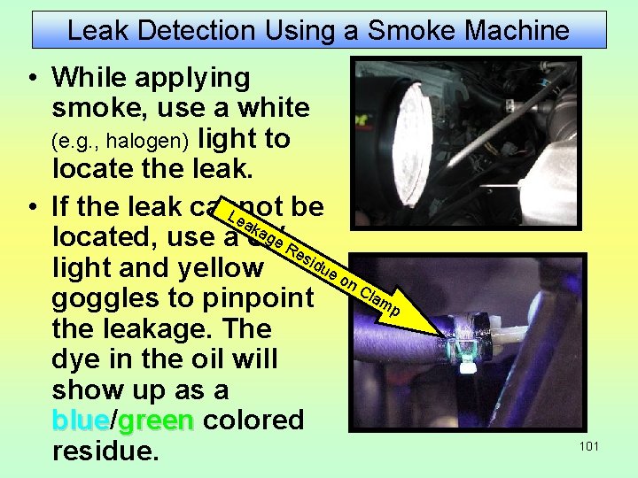
Leak Detection Using a Smoke Machine • While applying smoke, use a white (e. g. , halogen) light to locate the leak. • If the leak cannot be Le ak ag e. R located, use a UV es idu eo light and yellow n. C lam goggles to pinpoint p the leakage. The dye in the oil will show up as a blue/ blue green colored residue. 101
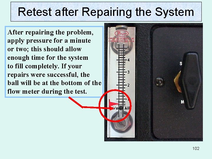
Retest after Repairing the System After repairing the problem, apply pressure for a minute or two; this should allow enough time for the system to fill completely. If your repairs were successful, the ball will be at the bottom of the flow meter during the test. 102
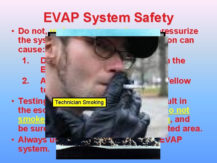
EVAP System Safety • Do not, under any circumstances, pressurize the system with an air hose. This action can Plus EVAP Testing = BYE TECHNICIAN cause: 1. Damage to many components in the EVAP system. 2. A vapor hazard to yourself and fellow technicians. • Testing of. Technician the EVAP Smokingsystems can result in the escape of explosive fuel vapor. Do not smoke while testing the EVAP system, and be sure the vehicle is in a well ventilated area • Always use nitrogen gas to test an EVAP system.

MODE 6 DIAGNOSTICS
MODE 6 Diagnostics You might be asking yourself, “So what is this Mode 6, and how can it help me diagnose vehicle emission problems? ” – Mode 6 tests can assist you to confirm the success of repairs you performed that are related to a non-continuous monitor. – Mode 6 test values (and pending DTCs) are available to the technician on the first trip of a two trip monitor. – Mode 6 test results can give you an indication if a monitored system (component) is close to failing a monitor test. 105
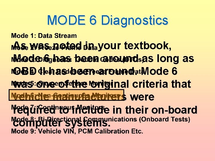
MODE 6 Diagnostics As was noted in your textbook, Mode 6 has been around as long as OBD II has been around. Mode 6 was one of the original criteria that vehicle manufacturers were required to include in their on-board computer systems.
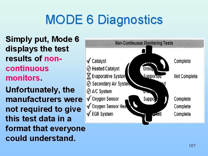
MODE 6 Diagnostics Simply put, Mode 6 displays the test results of noncontinuous monitors. Unfortunately, the manufacturers were not required to give this test data in a format that everyone could understand. 107
MODE 6 Diagnostics To display the non-continuous monitor test results, some manufacturers (engineers) used the Hexadecimal system (dollar sign - $04) to indicate test information. The Hexadecimal number is based on 16, using numbers and letters to identify a value: 0, 1, 2, 3, 4, 5, 6. 7, 8, 9, A, B, C, D, E, F. This system can convey many values using just four characters. Good for them, not so good for the technician trying to decipher this number/letter combination.
MODE 6 Diagnostics Fortunately, some scan tool manufacturers have converted the engineering jargon on their tools into terms an average person can understand. For a technician to use Mode 6, they need to know some basic terms:
Terms Used in Mode 6 Data 1. TID = Test Identification – The system being tested (MIDs = Monitor Identification in CAN systems) 2. CID = Component Identification – The component of the system being tested. 3. TLT = Test Limit – To pass a test, a test value must be either a minimum or maximum value ( or between a min/max value) min 4. Hexadecimal ($) = Numeric/Alpha unit that indicates a specific TID/CID or test value (Example: $02) 5. Raw Data = Numeric data indicating the actual test results. 6. Manufacturer’s Conversion Factor = A value supplied by the manufacturer, to convert test data to values that can be used to diagnose a system (volts, Ohms, amps, inches of mercury, etc. ). 7. Test Value = Actual test results. 8. Results = Indicates whether system/component either passed or failed a test. 9. Limit Type = Test pass/fail limits.
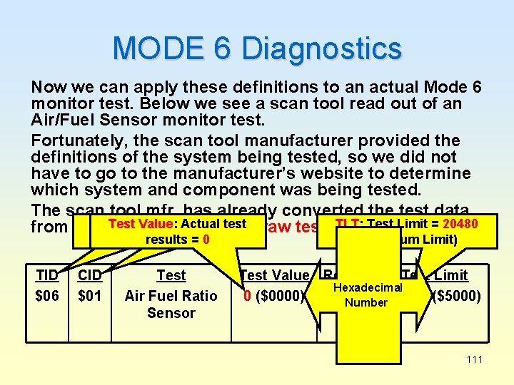
MODE 6 Diagnostics Now we can apply these definitions to an actual Mode 6 monitor test. Below we see a scan tool read out of an Air/Fuel Sensor monitor test. Fortunately, the scan tool manufacturer provided the definitions of the system being tested, so we did not have to go to the manufacturer’s website to determine which system and component was being tested. The scan tool mfr. has already converted the test data Test TID CID =Value: Test = Component Actual test TLT: Value TLT Test Limit = 20480 from a hexadecimal code to raw test data. Identification results Identification =0 TID $06 CID $01 Test Air Fuel Ratio Sensor (Maximum Limit) Test Value Results Test Limit Hexadecimal 0 ($0000) Pass 20480 ($5000) Number 111
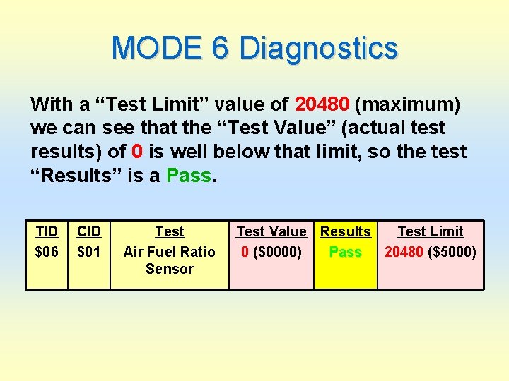
MODE 6 Diagnostics With a “Test Limit” value of 20480 (maximum) we can see that the “Test Value” (actual test results) of 0 is well below that limit, so the test “Results” is a Pass. TID $06 But, CID $01 Test Value Results Test Limit Air Fuel Ratio 0 ($0000) Pass 20480 ($5000) what if things Sensor were different?

MODE 6 Diagnostics An OBD II vehicle indicates that all monitors have been set and passed except for one - the CAT monitor. There are no DTCs, and the tech has tried every drive cycle in the book, with no success. In desperation, he checks the Mode 6 test results, and finds the following results for the Air/Fuel Sensor monitor test: TID $06 CID $01 Test Air Fuel Ratio Sensor Test Value Results Test Limit 20475 Pass 20480 ($5000) ($4 FFB) 113
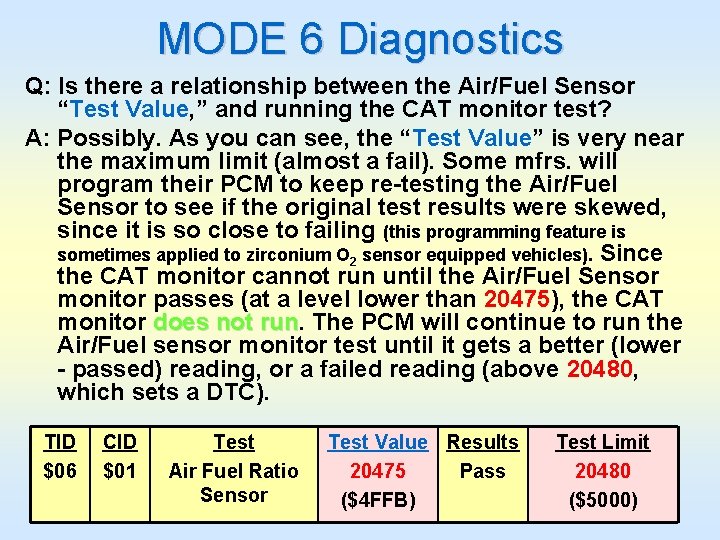
MODE 6 Diagnostics Q: Is there a relationship between the Air/Fuel Sensor “Test Value, ” and running the CAT monitor test? A: Possibly. As you can see, the “Test Value” is very near the maximum limit (almost a fail). Some mfrs. will program their PCM to keep re-testing the Air/Fuel Sensor to see if the original test results were skewed, since it is so close to failing (this programming feature is sometimes applied to zirconium O 2 sensor equipped vehicles). Since the CAT monitor cannot run until the Air/Fuel Sensor monitor passes (at a level lower than 20475), the CAT monitor does not run The PCM will continue to run the Air/Fuel sensor monitor test until it gets a better (lower - passed) reading, or a failed reading (above 20480, which sets a DTC). TID $06 CID $01 Test Air Fuel Ratio Sensor Test Value Results 20475 Pass ($4 FFB) Test Limit 20480 ($5000) 114
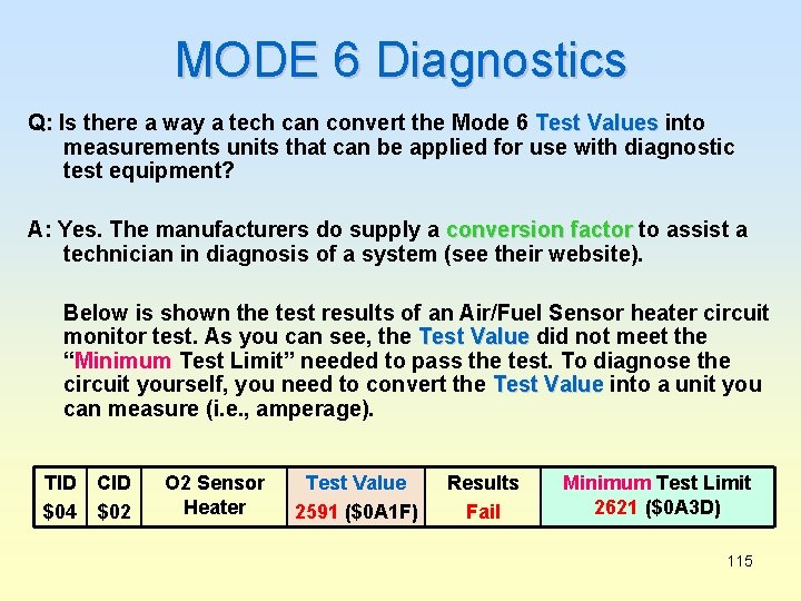
MODE 6 Diagnostics Q: Is there a way a tech can convert the Mode 6 Test Values into measurements units that can be applied for use with diagnostic test equipment? A: Yes. The manufacturers do supply a conversion factor to assist a technician in diagnosis of a system (see their website). Below is shown the test results of an Air/Fuel Sensor heater circuit monitor test. As you can see, the Test Value did not meet the “Minimum Test Limit” needed to pass the test. To diagnose the circuit yourself, you need to convert the Test Value into a unit you can measure (i. e. , amperage). TID $04 CID $02 O 2 Sensor Heater Test Value 2591 ($0 A 1 F) Results Fail Minimum Test Limit 2621 ($0 A 3 D) 115
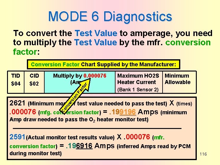
MODE 6 Diagnostics To convert the Test Value to amperage, you need to multiply the Test Value by the mfr. conversion factor: factor Conversion Factor Chart Supplied by the Manufacturer: Multiply by 0. 000076 (Amps) or CID $02 Maximum HO 2 S Minimum Heater Current Allowable (Bank 1 Sensor 2) si on Fa ct TID $04 Co nv er 2621 (Minimum monitor test value needed to pass the test) X (times). 000076 (mfg. conversion factor) factor =. 199196 Amps (minimum Amp draw needed to pass the O 2 heater monitor test) 2591(Actual monitor test results value) X. 000076 (mfr. conversion factor) factor =. 196916 Amps (inferred Amps read by PCM during monitor test) 116
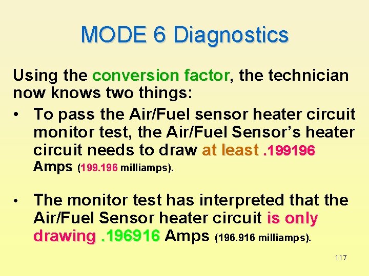
MODE 6 Diagnostics Using the conversion factor, factor the technician now knows two things: • To pass the Air/Fuel sensor heater circuit monitor test, the Air/Fuel Sensor’s heater circuit needs to draw at least. 199196 Amps (199. 196 milliamps). • The monitor test has interpreted that the Air/Fuel Sensor heater circuit is only drawing. 196916 Amps (196. 916 milliamps). 117
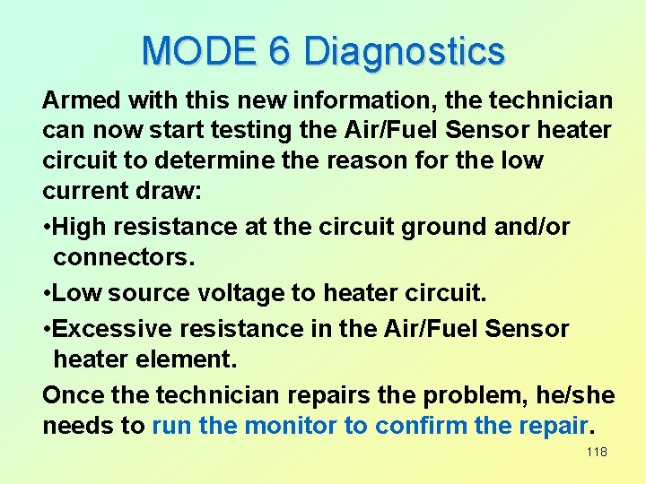
MODE 6 Diagnostics Armed with this new information, the technician can now start testing the Air/Fuel Sensor heater circuit to determine the reason for the low current draw: • High resistance at the circuit ground and/or connectors. • Low source voltage to heater circuit. • Excessive resistance in the Air/Fuel Sensor heater element. Once the technician repairs the problem, he/she needs to run the monitor to confirm the repair. 118
TSBs, PCM REPROGRAMING, & MFR. WEBSITES At the pace that technology is evolving, today’s Smog Check technician cannot consistently repair emission and driveability problems, unless they use Technical Service Bulletins (TSBs), PCM Reprogramming, and manufacturer websites. 119
Technical Service Bulletins (TSBs) are issued by the vehicle manufacturer to advise technicians that a particular vehicle has a recurring problem. The TSB usually includes a repair procedure, information on the part(s) that need to be replaced, and any warranty information. 120
Technical Service Bulletins After you have identified the initial area causing the emissions/driveability problem, your next step should be to consult any TSBs that might be related to the identified problem. By not including TSBs in your diagnostic process, you risk performing unnecessary diagnostic steps, or worse, installing unnecessary parts. 121
TSBs & PCM Reprogramming Many TSBs require reprogramming (recalibration) of the PCM to fix a known problem(s). Failing to reprogram a PCM that needs an update can result in wasted diagnostic time, and unnecessary repairs. Independent repair shops now have access to affordable reprogramming equipment. The Society of Automotive Engineers (SAE) has established standards (SAE 2534) for aftermarket tool manufacturers to provide “Pass-Thru” PCM reprogramming equipment. 122
PCM REPROGRAMMING Reprogramming a PCM is relatively simple. First obtain the PCM calibration update program from the manufacturer (purchase their CD, or log on to their website). Download the program to a PC, and then follow the instructions provided on the screen. - NOTE It very important that the vehicle have a fully charged battery when reprogramming a PCM. Additionally, DO NOT remove the cable from the PC, or pass-thru module to the PCM during the reprogramming. 123
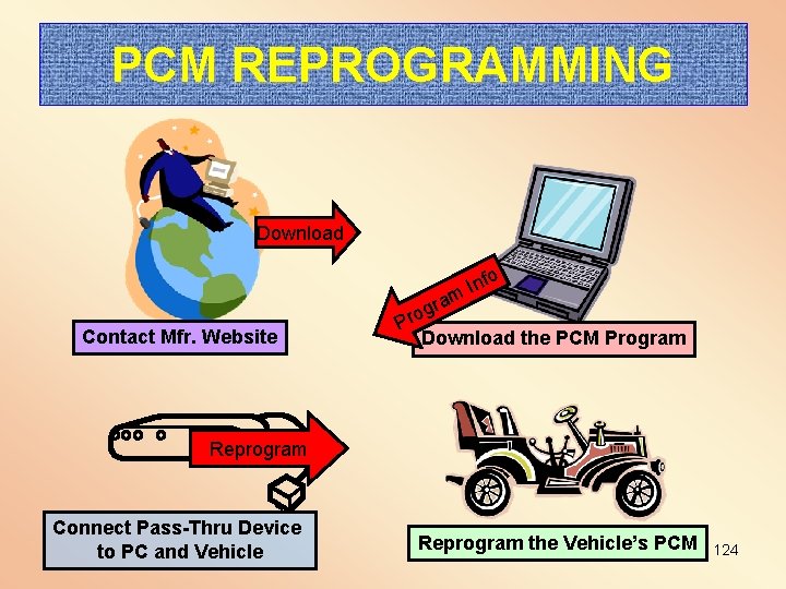
PCM REPROGRAMMING Download o Inf Contact Mfr. Website ram g Pro Download the PCM Program Reprogram Connect Pass-Thru Device to PC and Vehicle Reprogram the Vehicle’s PCM 124
Manufacturer Websites Vehicle manufacturers must provide a website for diagnostic and repair information on their vehicles at a reasonable cost. A list is on the National Automotive Service Task Force (NASTF) website: http: //www. nastf. org Example: A manufacturer’s website charges under $30. 00 to download (during a 24 hour period) a PCM calibration update program (using an SAE J 2534 pass-thru device). Pass 125 -thru devices cost from $1, 300 -$1, 600.
CASE STUDY A 1996 Ford V-8 (5. 0 L) was failing the ASM 50/15 test for high NOx. The technician diagnosed a ‘no EGR flow’ (i. e. , vacuum) condition at that speed/load; but he did get flow (EGR vacuum) during the 25/25 test. After hours of checking the EGR valve operation, vacuum hose routing, and other input sensors and grounds, he checked to see if there was a TSB on this problem. Ford had a PCM calibration update that would address this problem. He downloaded the program into the vehicle’s PCM, EGR vacuum was restored and the vehicle’s NOx problem was cured – no bad parts, just a PCM update. 126
BAR Update Issues: • • CAP Related Issues: Inspection Issues: Repair Issues: Testing Equipment Issues: • Test-Only Issues: • Training Issues: 127
Issue: Should all shops inform customers whose vehicle fails a Smog Check inspection about the CAP program? • Comment: Yes. Test and Repair stations have an obligation to have a “Notice to Motorists” sign posted in an area consumers frequent and the station personnel should advise consumers in need of smog check repairs of the CAP program. Test-Only shop owners and technicians should alert consumers to the Consumer Assistance Program (CAP) program. CAP provides financial assistance for qualified owners whose vehicles fail their biennial (every-other-year) Smog Check. Motorists may qualify for Repair Assistance in one of two ways: – Income Eligible – Motorists whose household incomes are at or below 200% of the federal poverty guidelines qualify for up to $500 in repair assistance. Qualified consumers must pay the first $20 towards diagnosis and/or emissions-related repairs. – Test-Only Eligible – Certain vehicles are required to have their Smog Check inspections done at Test-Only stations. If the vehicle’s DMV registration renewal notice requires a Test-Only inspection, the vehicle may qualify for up to $500 in repair assistance. Qualified consumers must pay the first $100 towards diagnosis and/or emissions-related repairs. Shop owners, technicians, and consumers can obtain CAP program information and a CAP application by visiting the BAR Web site at www. smogcheck. ca. gov or by calling the Department of Consumer Affairs Consumer Information Center at 1 -800 -952 -5210. 128
Issue: If the check engine light comes on during an ASM test, should the vehicle fail the inspection? • Comment: No. To minimize failures due to vehicle incompatibility (false failures), BAR revised the procedures to only fail a vehicle if the check engine light comes on during a functional test. The test procedure says to assess MIL pass/fail status only during the MIL functional test part of the vehicle’s Smog Check inspection. This does not apply to OBD II vehicles because the MIL illumination is an automatic fail made by the BAR 97. However, in OBD I vehicles, the MIL light may light for non emission related codes. By following the MIL functional test procedure, as described in the Smog Check Inspection Manual, technicians can minimize the potential for MIL illumination for non emission related codes. 129
Issue: Should the technician run a “complete” Smog Check, even if the technician senses the vehicle will fail the emissions test? • Comment: Yes. If the customer authorizes a full inspection, the technician needs to run a complete test on the vehicle. It may be appropriate for the technician to discuss the pre-inspection option with the customer. In order for a consumer to qualify for CAP, they will need to have a complete initial Smog Check Inspection, or an official preinspection. Aborted tests or Training mode tests are not acceptable 130
Issue: Are some Smog Check Technicians incorrectly performing the visual inspection for tampered emission control systems? • Comment: Yes. Technicians MUST verify that all required emission control systems/devices are present and free of tamper(s) and/or defects as defined in the Smog Check Inspection Manual. Technicians shall enter the results of the visual inspection, as prompted by the analyzer. If any required emission control system is tampered (missing, modified, disconnected) or defective, the vehicle shall fail the Smog Inspection. 131
Issue: Should Smog Check technicians check ignition timing as part of the Smog Check inspection? • Comment: Yes, except for vehicles with an under hood label that states “non adjustable” and/or vehicles with computer controlled ignition systems that do not have conventional timing adjustments. For all other vehicles, checking the ignition timing is a required procedure during the Smog Check inspection. 132
Issue: Are some technicians not repairing vehicles to the “average” emission levels shown on the VIR? • Comment: Technicians must perform a full emission failure diagnosis prior to making any repair recommendations to the customer. The diagnosis and repair should be based upon restoring the vehicle to original manufacturer specifications. Repairing a vehicle in this manner will likely result in emission readings well within the average emission levels. An attempt to repair a vehicle just to the pass the fail point. is a disservice to the consumer who expects their vehicle to be repaired to manufacturer standards. 133
Issue: Can one Smog Check technician enter another technician’s repairs? • Comment: Yes. The repairs must be entered as prompted by the analyzer. However, this does not mean that one technician can perform a partial or full smog inspection for another technician. 134
Issue: How should a technician handle a vehicle that won’t communicate during an OBD II functional test, but the scan tool says the vehicle is OK and the vehicle is not listed in Appendix J? • Comment: The OBD II functional test must not be overridden. The customer should either be sent to another station where the BAR 97 EIS can communicate with the vehicle, or be referred to the Referee. 135
Issue: Are Test-Only stations required to give estimates to customers for initial inspections or free retests? • Comment: Yes. Regulations require that a station provide each customer a written estimate of work to be performed, prior to performing any service or repair, even if there is no charge for the service or repair. [See Section 9884. 9(a) of the Business & Professions (B&P) Code, and section 3353(a) of the California Code of Regulations (CCR)]. 136
Issue: Are Test-Only stations required to obtain customers authorization on the work order prior to testing? • Comment: Yes. Customer authorization means consent, and shall consist of the customer’s signature on the work order taken before work begins. [Reference sections: 9884. 9(a) B&P, and 3353(a) CCR, 3303(k) CCR]. 137
Issue: Are Test-Only stations and Test and Repair stations required to document a customer’s additional authorization for services and repairs? • Comment: Yes. Test-Only stations and Test & Repair stations must list all: authorization, service work, and parts on the work order and the repair facility and customer invoice; even if there is no charge for the service or repair. Stations are required to comply with sections 9884. 9(a) B&P and Section 3353(a) CCR. 138
Issue: Are Test-Only technicians allowed to direct customers to specific repair facilities? • Comment: No. A Test-Only station may not refer a vehicle owner to a particular provider of motor vehicle repair services for emissions related repairs. In accordance with Title 16, Section 3340. 16 CCR, Test-Only stations must make available a list, prepared by BAR, of the Smog Check stations in their region. This list can be found on BAR’s Smog Check web site: www. smogcheck. ca. gov, or by contacting a local BAR field office. 139
Issue: Should technicians in Test-Only stations run the monitors as part of their Smog Check inspection? • Comment: No. Technicians in Test-Only stations should perform the Smog Check inspection, per the Smog Check Manual. Since the Smog Check Inspection Manual does not stipulate running monitors as a Test-Only inspection function, the technician shall not run the monitors as part of the Smog Check inspection. 140
Issue: Can a Smog Check station sublet its smog inspections to a Test-Only station? • Comment: No. A Smog Check inspection cannot be sublet. 141
Issue: How can a technician determine if an aftermarket part, with a CARB Executive Order (EO) number, is meant for the vehicle they are testing? • Comment: Technicians are required to verify the EO number as being applicable to the vehicle they are testing. If the part is not applicable to the vehicle they are testing, then the vehicle fails the visual inspection for a modified emission control system part. 142
ACKNOWLEDGEMENTS The Bureau of Automotive Repair would like to thank the following individuals for their contributions to this presentation: • Myron Maurseth – C. I. A. T. • Rick Escalambre – Skyline College • Glenn Richardson – Star Enviro. Tech Inc. • Jim Moore – Delphi Inc. • Dave Crippen & Steve Pratt – Vetronix Bosch Group • Tejinder Singh – Wyo. Tech • Evan Meyer – Automotive Instructor • Jerry “G” Truglia – ATTS 143 • Marty Gunn - BAR

THE END HAVE A NICE DRIVE HOME 144
- Slides: 144