Title Superconducting THz Transmission Spectrometer Comprising Josephson Oscillator


- Slides: 24

Title Superconducting THz Transmission Spectrometer Comprising Josephson Oscillator and Cold-Electron Bolometer M. Tarasov, L. Kuzmin, E. Stepantsov, I. Agulo, A. Kalabukhov, T. Claeson

Outline • • Cold electron bolometer concept Bolometer samples Josephson oscillators Experimental setup Terahertz response Josephson and thermal radiation Conclusion

CEB chip layout • 4 junction structure for cooling/heating • Log-periodic antenna for 0. 2 -2 THz range • Double-dipole antenna for 600 GHz • Double-dipole antenna for 300 GHz

Center part of LPA Logperiodic antenna designed for frequency range 0. 22 THz. Absorber length is 10 mm

LPA SEM image Double dipole antenna designed for 300 GHz central frequency

SEM view of the LPA center SINIS bolometer inside the double dipole antenna. Absorbel length is 10 mm

AFM picture of CEB

He 3 sorption cooler

Quasioptical schematics CEB JJ oscillator

Sample holders Quasioptical sample holders with silicon and sapphire extended hyperhemisphere lenses and pogopins for contacts

Back-to-back configuration

Sample holder

YBa. Cu. O film on tilted substrate SPM view of the 250 nm YBa. Cu. O film on 14 o tilted sapphire substrate. Subgrains are elongated in the ab plane perpendicular to tilt direction

Bicrystal Josephson junction SPM view of the YBa. Cu. O bridge across the bicrystal grain boundary. Bridge length is 5 mm, width below 1 mm.

Josephson chip layout

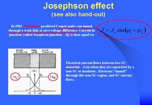
IV curve and Shapiro steps IV curve of Josephson junction at 4. 2 K without radiation (dashed) and under 300 GHz irradiation when critical current is completely suppressed

Current and voltage response Response of a 10 k. W bolometer measured at 260 m. K by applying a dc power to external junctions

Josephson radiation and overheating Radiation from a 55 W Josephson junction with Ic=10 m. A and when ctritical current is suppressed to zero by magnetic field

Overheating of the Josephson junction Temperature of the Josephson microbridge Planck’s radiation law , neglecting Tp For our design frequency 300 GHz and bias range up to 5 m. V, it can be roughly fitted with the approximate expression

Log-periodic and double dipole Response of bolometer with a double-dipole antenna (black) and a log-periodic antenna (blue) under rediation from the same Josephson junction with log-periodic antenna

Magnetic field influence Signal from a Josephson junction with Ic=400 m. A (black) and suppressed down to 150 m. A (blue), measured by bolometer with a double-dipole antenna

Terahertz response Dependence of bolometer response on the frequency of the first harmonic of Josephson oscillations. Last maximum corresponds to 1. 7 THz.

Conclusion We demonstrated the response of a normal metal cold electron bolometer at frequencies up to 1. 7 THz. A voltage response of the bolometer is 4. 108 V/W and an amplifier-limited technical noise equivalent power 1. 3. 10 -17 W/Hz 1/2. We were first to use electrically tunable high critical temperature Josephson quasioptical oscillator as a source of radiation in the range 0. 2 -2 THz. A high critical temperature Josephson junction operated at temperature about 2 K shows a Ic. Rn product over 4. 5 m. V that enables an oscillation frequency over 2 THz. Combination of a Terahertz-band Josephson junction and a hot electron bolometer brings a possibility to develop a quasioptical cryogenic compact transmission spectrometer with a resolution of about 1 GHz. Such cryogenic spectrometer can be used for low-temperature spectral evaluation of any cryogenic detector, quasioptical submm wave grid filter, neutral density filter, absorber, etc. Cold electron bolometer detected that a Josephson junction is overheated by a transport current even when it is placed on millikelvin stage.

Per aspera ad astra
 Thz hannover
 Boris chichkov
 Mkid
Mkid Superconducting tunnel junction
 Superconducting electronics
 Superconducting ring
 Stj
Stj Western superconducting
 Superconducting devices in quantum optics
 Coband
 Superconducting
 Oxford superconducting technology
 Superconducting tunnel junction
 Chris josephson
 Vi/vt vereckei
 Josephson c700s
 Josephson junction
 Josephson junctions
 Högerställd elaxel
 Josephson devices
 Josephson junction
 Josephson effect
 Michael josephson ethics
 Alexander golubov
 Josephson institute of ethics


