The Relativistic Heavy Ion Collider highintensity polarized H


 ~1014 cm-2")


 H- ion beam in LEBT. 31. 5 + (7.")


 vs. SCS magnetic field in He and Rb-cells Magnetic")


- Slides: 41
The Relativistic Heavy Ion Collider high-intensity polarized H- ion source A. Zelenski, G. Atoian, D. Raparia, J. Ritter, D. Steski Brookhaven National Laboratory • • • Optical pumping polarization technique Charge-exchange collisions High-brightness atomic beam source He-ionizer cell Sodium-jet ionizer cell Summary ICIS 2015, August 28, 2015
Summary • The old RHIC OPPIS based on ECR primary proton source retired after successful operation in Runs 2000 -2012. • The new source with atomic beam hydrogen injector and He-ionizer was developed in 2010 -12 and commissioned for operation in Run-2013. • It produces significantly higher brightness primary proton beam which resulted in higher polarized beam intensity and polarization delivered for injection to Linac-Booster-AGS-RHIC accelerator chain. • Practically all OPPIS systems were modified (in addition to the ECRsource): a new superconducting solenoid; new He-ionizer cell with a pulsed He-injection and new pulsed electro-magnetic gas valve; beam energy separation system developed for un-polarized residual beam suppression; new vacuum system with turbo-molecular pumps for He-pumping; laser control, diagnostics and transport systems.
The RHIC OPPIS upgrade with atomic hydrogen injector, Run-2013 -15 BNL - BINP, Novosibisk -INR, Moscow collaboration
Polarization facilities at RHIC L max = 1. 6 1032 s-1 cm-2 50 < √s < 510 Ge. V RHIC p. C “CNI” polarimeters Absolute H-jet polarimeter PHENIX RHIC STAR Siberian Snakes Spin Rotators Pol. H- ion source LINAC AGS, 24 Ge. V 200 Me. V polarimeter BOOSTER, 2. 5 Ge. V AGS p. C “CNI” polarimeter
RHIC Polarized beam in Run 2013 -15 OPPIS 1. 0 m. A x 300 us→ 18∙ 1011 polarized H- /pulse. 9. 0 ∙ 1011 polarized H- /pulse at 200 Me. V routinely in Run-15 LINAC Booster (2. 5 -3. 0) ∙ 1011 protons /pulse at 2. 3 Ge. V AGS ~1. 8∙ 1011 p/bunch, P~60 -65% at 100 Ge. V P ~ 58% at 255 Ge. V It is expected, that use of Electron Lens will allow increase of the bunch intensity to ~2. 5∙ 1011 p/bunch. (2. 0 -2. 5) ∙ 1011 p/bunch RHIC
What can we learn about “swiss” watches from watches collisions? Actually a lot! In particular, if protons are polarized!
Intermediate bozons W± - can be produced directly in electroweak processes in collisions of polarized proton beams of a 250 Ge. V energy at RHIC. In this case parity-violation can be as large as 50% and spin-correlation can be used for studies of different flavor quark contribution to the proton spin.
SPIN -TRANSFER POLARIZATION IN PROTON-Rb COLLISIONS Laser-795 nm Optical pumping Rb: NL(Rb) ~1014 cm-2 Rb+ Proton source Na-jet ionizer cell: NL(Na)~ 3 • 1015 cm-2 Rb+ H+ H+ Sona transition ~50 m. A, 2. 8 ke. V H- 1. 5 k. G field ECR-29 GHz Н+ source Ionizer cell Supperconducting solenoid 25 к. Гс Charge-exchange collisions: ~10 -14 cm 2 Electron to proton polarization transfer Laser beam is a primary source of angular momentum: 10 W (795 nm) 4 • 1019 h /sec 2 A, H 0 equivalent intensity.
Optical Pumping polarization technique. A. Kastler, Nobel prize 1966 MJ = -1/2 m 5 n λ 9 =7 l 1. 56 e. V r ula o y. P la t d e riz 5 P 1/2 h lig rc Ci MJ = +1/2 n. LJ Spontaneous decays. 5 S 1/2 MJ = -1/2 relaxation MJ = +1/2 ~ 100% polarized Rb atoms! Optical pumping application is limited by available laser power!? Recent progress in laser technology is very promising for new applications.
Pulsed OPPIS with the atomic hydrogen injector at INR, Moscow, 1982 -1990. First generation Atomic H 0 injector Helium ionizer cell ~80% ionization efficiency. H- current- 0. 4 m. A H+ current- 4. 0 m. A, P=65%, 1986 Lamb-shift polarimeter
New generation OPPIS with atomic H 0 injector High-brightness proton beam inside strong 2. 5 T solenoid field produced by atomic H beam ionization in the He-gas ionizer cell Atomic H injector HHe-cell The proton beam intensity is about 1. 0 A !
Hydrogen atomic beam ionization efficiency in the He- cell H 0 + He → H+ + He + e 80% 10 ke. V
“Fast Atomic Beam Source”, BINP, Novosibirsk, 2012 Plasmatron 4 -grid proton extraction system ~ 3. 5 A equivalent H 0 beam H 2 Neutralization cell FABS produces 200 -300 m. A equivalent H 0 beam intensity Within the Na-jet ionizer acceptance.
FABS 4 -grid spherical Ion Optical System 1820 holes , 1. 0 mm in diameter 3 -5 A of proton beam At 6 -8 ke. V energy
FABS and neutralizer cell.
Neutral hydrogen beam intensity profile at 250 cm distance from the source. FWHM ~ 20 mm
Residual un-polarized H 0 beam component suppression by the energy separation H 0 + He → H+ + He + e H 0(6. 5 ke. V) Deceleration Rb -cell He-ionizer cell H+(70%) H 0(2. 5 ke. V) H 0(30%) -4. 1 k. V -4. 0 k. V -4. 1 k. V -2 -3 k. V +0. 1 k. V H 0(6. 5 ke. V)
He-ionizer cell and 3 -grid energy separation system. He-pulsed valve 3 -grid beam deceleration system
“Electro-magnetic” valve operation principle. Force to the conducting plate in the (high ~ 3 T) magnetic field. For I=100 A, L=5 cm, F=15 N). F I B
New OPPIS with atomic H 0 injector layout, 2013 CP 1 TMP 1 Neutralizer H 2 -cell He-ionizer cell Atomic H injector H+ H 2 H 0 Rb-cell He H+ Sona transition Rb H 0 Na-jet cell Na H-
H- yield vs. H 0 beam energy.
Sodium-jet ionizer cell Transversal vapor flow in the N-jet cell. Reduces sodium vapor losses for 3 -4 orders of magnitude, which allow the cell aperture increase up to 3. 0 cm. Nozzle 500 deg. C Collector ~150 deg. C NL ~2· 1015 atoms/cm 2 L ~ 2 -3 cm Reservoir ~500 deg. C Reservoir– operational temperature. Tres. ~500 о. С. Nozzle – Tn ~500 о. С. Collector- Na-vapor condensation: Tcoll. ~120 о. С Trap- return line. T ~ 120 – 180 о. С.
H- beam acceleration to 35 ke. V at the exit of Na-jet ionizer cell H 35 ke. V H 0 39 ke. V 3 ke. V 7 kev -32 k. V -28 ke. V -15 ke. V Na-jet cell is isolated and biased to – 32 ke. V. The H- beam is accelerated in a two-stage acceleration system.
H- beam acceleration to 35 ke. V at the exit of Na-jet ionizer cell. H 35 ke. V -32 k. V -28 ke. V -15 ke. V Na-jet cell is isolated and biased to – 32 ke. V. The H- beam is accelerated in a two-stage acceleration system.
Low Energy Beam Transport line. Variable collimator In DB 2 to improve Energy resolution. 23. 7 deg bender RFQ OPPIS FC 4 35. 0 ke. V Lamb Shift Polarimeter FC-Tk 1, 750 ke. V
Energy separation of decelerated (“polarized”) H- ion beam in LEBT. 31. 5 + (7. 5 – 4. 0) = 35 ke. V 31. 5 k. V 1400/30=47
06 Dec, 2013 Polarized H-current at 750 ke. V energy Note#31, page 75 (after RFQ) vs. Rb-cell temperature Beam. Energy=6. 5 ke. V; IONZ=220 A; 1. 0 m. A × 300 us =18× 1011 ions/pulse 12 u. A NL~10× 1013 atoms/cm 2 Rb cell temperature, deg. C
Polarized H- current-1. 05 m. A, after RFQ 750 ke. V Rb-98º 200 u. A/div 100 us/div
Rb-90, 200 Me. V, T 9 -620 u. A 600 µA × 400 µs → 14. 4 ∙ 1011 protons/pulse
Polarization (at 200 Me. V) vs. SCS magnetic field in He and Rb-cells Magnetic field , k. G
Source intensity and polarization. • Reliable long-term ∙operation of the source was demonstrated. • Very high suppression of un-polarized beam component was demonstrated. • Small beam emittance (after collimation for energy separation) and high transmission to 200 Me. V. Rb-cell thickness-NL Linac Current, μA 4. 5 500 5. 5 560 7. 5 680 Booster Input × 1011 9. 0 10. 0 12. 2 13. 5 Pol. %, at 200 Me. V 84 83 80. 5 Rb-cell thickness , NL × 1013 atoms/cm 2 10. 4 750 78
H- beam current and polarization at 200 Me. V vs. Rb vapor thickness Polarization in 200 Me. V polarimeter H- ion beam current (m. A) Rb-vapor thickness –n. L –atoms/cm 2
Equal 12 deg and 16 deg polarization numbers Polarization at 200 Me. V -85. 2%
Long-term polarization stability, April 14 -23, 2014 86%
Polarization in AGS, 23 Ge. V
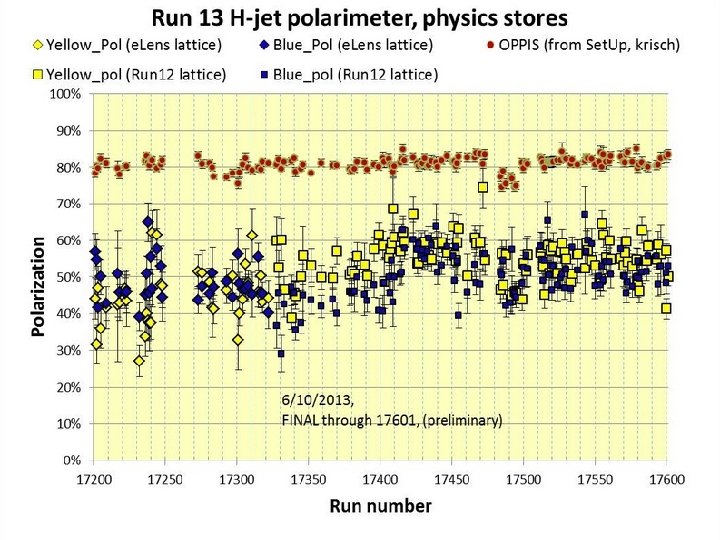
Polarization measurements at 255 Ge. V in H-jet polarimeter, Run-2013, April-25 -30 < ~ 62% in collisions
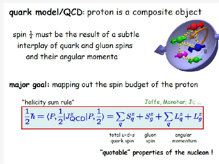
High intensity polarized proton sources makes feasible the high luminosity RHIC operation to study: § spin proton structure, §fundamental tests of QCD and electroweak interaction.
Summary • The old RHIC OPPIS based on ECR primary proton source was retired after successful operation in Runs 2000 -2012. • The new source with atomic beam hydrogen injector and Heionizer was developed in 2010 -12 and commissioned for operation in Run-2013. • It produces significantly higher brightness primary proton beam which resulted in higher polarized beam intensity and polarization delivered for injection to Linac-Booster-AGS-RHIC accelerator chain. • Practically all OPPIS systems were modified (in addition to the ECR-source): a new superconducting solenoid; new Heionizer cell with a pulsed He-injection and new pulsed electrodynamic gas valve; beam energy separation system developed for un-polarized residual beam suppression; new vacuum system with turbo-molecular pumps for He-pumping; laser control, diagnostics and transport systems.