The principle of superposition The resultant displacement at


 The intensity of the receiver signal decreases")
 The intensity of the receiver signal decreases")
 The intensity of the receiver signal")
 The intensity of the receiver signal decreases")
 The intensity of the receiver signal decreases")
 The intensity of the")


- Slides: 28
The principle of superposition The resultant displacement at any point is the sum of the separate displacements due to the two waves Eg: with a slinky coil spring
The principle of superposition The resultant displacement at any point is the sum of the separate displacements due to the two waves Eg: with a slinky coil spring
The principle of superposition The resultant displacement at any point is the sum of the separate displacements due to the two waves Eg: with a slinky coil spring supercrest
The principle of superposition The resultant displacement at any point is the sum of the separate displacements due to the two waves Eg: with a slinky coil spring supercrest
Two square waves superposing:
Two square waves superposing:
Two square waves superposing:
Superposition of sine waves:
Superposition of sine waves:
Superposition of sine waves: A square wave can be made up from several sine waves of higher frequencies
Phase changes on reflection LONGITUDINAL PULSE TRANSVERSE PULSE
Phase changes on reflection LONGITUDINAL PULSE TRANSVERSE PULSE
Phase changes on reflection LONGITUDINAL PULSE TRANSVERSE PULSE
Phase changes on reflection LONGITUDINAL PULSE TRANSVERSE PULSE
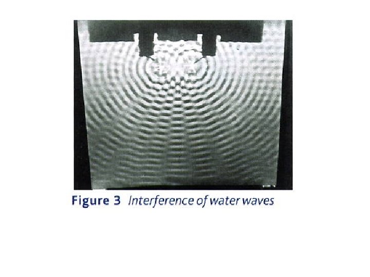
Interference effects Two dippers in a ripple tank can cause circular wavefronts to re-inforce or cancel: Re-inforcement (constructive interference) Cancellation (destructive interference)
Interference effects Two dippers in a ripple tank can cause circular wavefronts to re-inforce or cancel: Re-inforcement (constructive interference) Cancellation (destructive interference) Coherent sources (of the same frequency and phase relationship) produce a stable interference pattern.
Signal strength x Experiments with microwaves: a) The intensity of the receiver signal decreases with distance from the transmitter. x
Signal strength x Experiments with microwaves: a) The intensity of the receiver signal decreases with distance from the transmitter. b) Microwaves are reflected off metal plates – similar to light on a mirror. x
Signal strength x x Experiments with microwaves: a) The intensity of the receiver signal decreases with distance from the transmitter. b) Microwaves are reflected off metal plates – similar to light on a mirror. c) Diffraction occurs at each slit (slit width is of similar magnitude to the wavelength)
Regions of reinforcement Experiments with microwaves: a) The intensity of the receiver signal decreases with distance from the transmitter. b) Microwaves are reflected off metal plates – similar to light on a mirror. c) Diffraction occurs at each slit (slit width is of similar magnitude to the wavelength) d) An interference pattern forms with regions of constructive and destructive interference
Regions of reinforcement Experiments with microwaves: a) The intensity of the receiver signal decreases with distance from the transmitter. b) Microwaves are reflected off metal plates – similar to light on a mirror. c) Diffraction occurs at each slit (slit width is of similar magnitude to the wavelength) d) An interference pattern forms with regions of constructive and destructive interference
Regions of reinforcement Regions of cancellation Experiments with microwaves: a) The intensity of the receiver signal decreases with distance from the transmitter. b) Microwaves are reflected off metal plates – similar to light on a mirror. c) Diffraction occurs at each slit (slit width is of similar magnitude to the wavelength) d) An interference pattern forms with regions of constructive and destructive interference
Two loud speakers emitting the same note can cause loud and quiet areas in front of the speakers rarefaction compressions
Two loud speakers emitting the same note can cause loud and quiet areas in front of the speakers rarefaction compressions Regions of reinforcement (LOUD)
Two loud speakers emitting the same note can cause loud and quiet areas in front of the speakers rarefaction When compressions (or rarefactions) arrive in phase from both speakers, constructive interference occurs, creating a loud region compressions Regions of reinforcement (LOUD) Regions of cancellation (QUIET)