RF source system design for Ci ADS Liepeng
- Slides: 21
RF source system design for Ci. ADS Liepeng SUN On behalf of Department of RF power and LLRF
Outline • Introduction of Ci. ADS Project • SSA design for the project • The solution to some problems • Summary 2
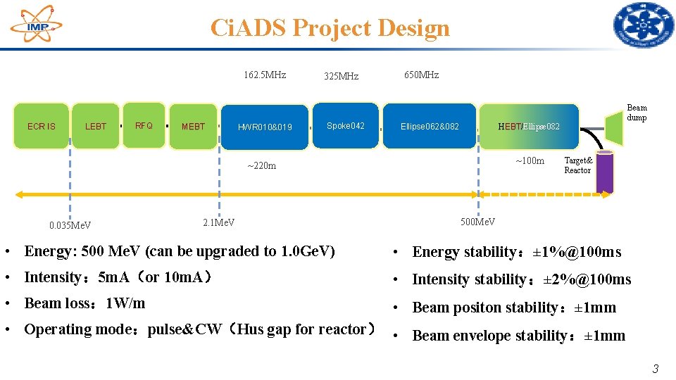
Ci. ADS Project Design 162. 5 MHz ECR IS LEBT RFQ MEBT HWR 010&019 325 MHz Spoke 042 650 MHz Ellipse 062&082 HEBT/Ellipse 082 ~100 m ~220 m 0. 035 Me. V 2. 1 Me. V Beam dump Target& Reactor 500 Me. V • Energy: 500 Me. V (can be upgraded to 1. 0 Ge. V) • Energy stability:± 1%@100 ms • Intensity: 5 m. A(or 10 m. A) • Intensity stability:± 2%@100 ms • Beam loss: 1 W/m • Beam positon stability:± 1 mm • Operating mode:pulse&CW(Hus gap for reactor) • Beam envelope stability:± 1 mm 3
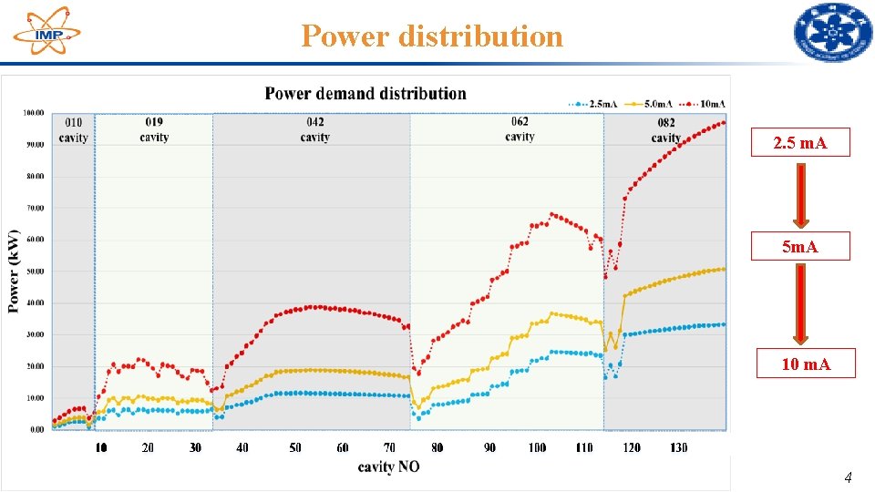
Power distribution 2. 5 m. A 5 m. A 10 m. A 4
SSA design for the project • RF strucure • Transmission line • The estimation of RF power • Specification of whole set 5
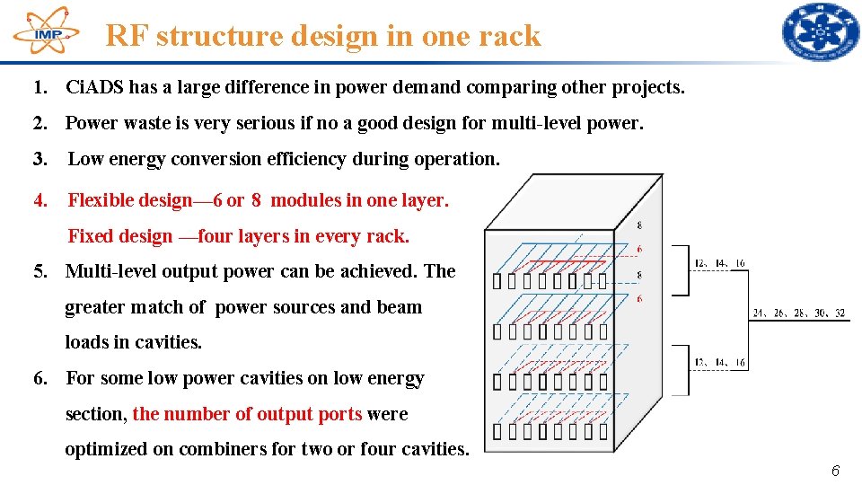
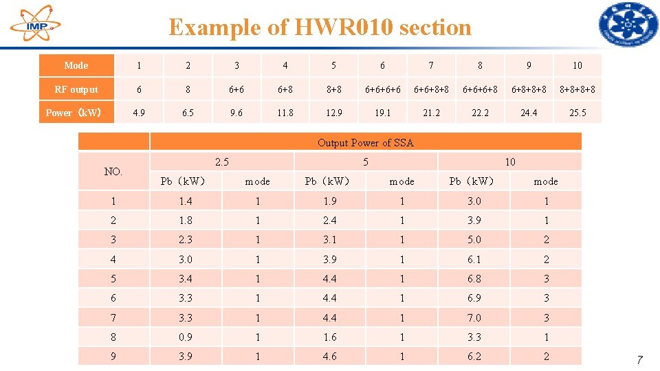
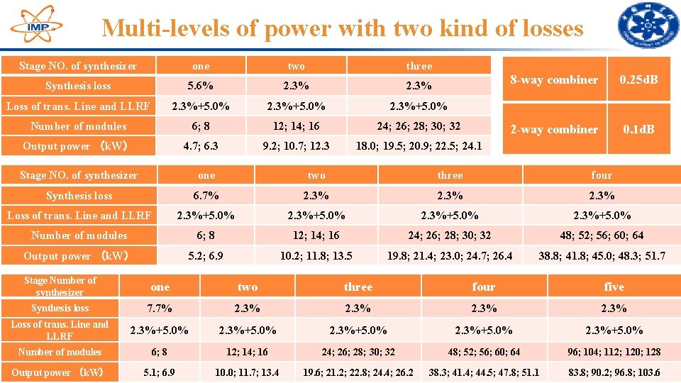
RF structure design in one rack 1. Ci. ADS has a large difference in power demand comparing other projects. 2. Power waste is very serious if no a good design for multi-level power. 3. Low energy conversion efficiency during operation. 4. Flexible design— 6 or 8 modules in one layer. Fixed design —four layers in every rack. 5. Multi-level output power can be achieved. The greater match of power sources and beam loads in cavities. 6. For some low power cavities on low energy section, the number of output ports were optimized on combiners for two or four cavities. 6
Example of HWR 010 section Mode 1 2 3 4 5 6 7 8 9 10 RF output 6 8 6+6 6+8 8+8 6+6+6+6 6+6+8+8 6+6+6+8 6+8+8+8+8 Power(k. W) 4. 9 6. 5 9. 6 11. 8 12. 9 19. 1 21. 2 22. 2 24. 4 25. 5 Output Power of SSA NO. 2. 5 5 10 Pb(k. W) mode 1 1. 4 1 1. 9 1 3. 0 1 2 1. 8 1 2. 4 1 3. 9 1 3 2. 3 1 3. 1 1 5. 0 2 4 3. 0 1 3. 9 1 6. 1 2 5 3. 4 1 4. 4 1 6. 8 3 6 3. 3 1 4. 4 1 6. 9 3 7 3. 3 1 4. 4 1 7. 0 3 8 0. 9 1 1. 6 1 3. 3 1 9 3. 9 1 4. 6 1 6. 2 2 7
Beam power for every cavity 8
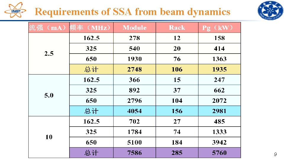
Requirements of SSA from beam dynamics 9
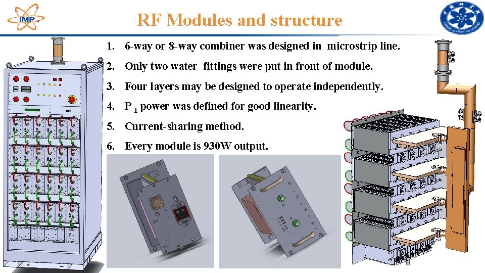
RF Modules and structure 1. 6 -way or 8 -way combiner was designed in microstrip line. 2. Only two water fittings were put in front of module. 3. Four layers may be designed to operate independently. 4. P-1 power was defined for good linearity. 5. Current-sharing method. 6. Every module is 930 W output. 10
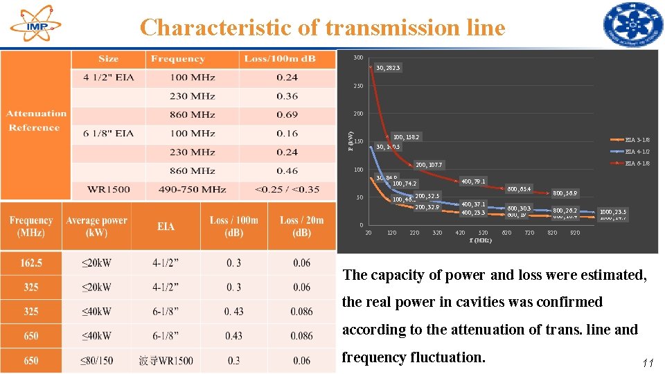
Characteristic of transmission line 300 30, 282. 3 250 P (k. W) 200 100, 158. 2 150 EIA 3 -1/8 30, 140. 5 EIA 4 -1/2 EIA 6 -1/8 200, 107. 7 100 30, 84. 9 100, 74. 2 400, 79. 1 600, 65. 4 200, 52. 5 100, 46. 5 200, 32. 9 50 400, 37. 1 400, 23. 3 600, 30. 3 600, 19 800, 56. 9 800, 26. 2 800, 16. 4 1000, 23. 5 1000, 14. 7 0 20 120 220 320 420 520 f (MHz) 620 720 820 920 The capacity of power and loss were estimated, the real power in cavities was confirmed according to the attenuation of trans. line and frequency fluctuation. 11
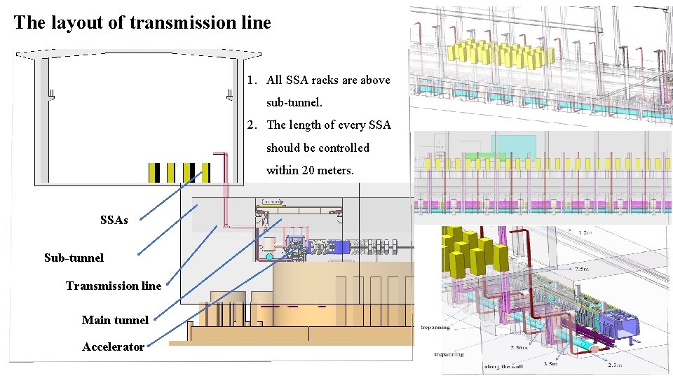
The layout of transmission line 1. All SSA racks are above sub-tunnel. 2. The length of every SSA should be controlled within 20 meters. SSAs Sub-tunnel Transmission line Main tunnel Accelerator
Multi-levels of power with two kind of losses Stage NO. of synthesizer one two three Synthesis loss 5. 6% 2. 3% Loss of trans. Line and LLRF 2. 3%+5. 0% Number of modules 6; 8 12; 14; 16 24; 26; 28; 30; 32 Output power (k. W) 4. 7; 6. 3 9. 2; 10. 7; 12. 3 18. 0; 19. 5; 20. 9; 22. 5; 24. 1 8 -way combiner 0. 25 d. B 2 -way combiner 0. 1 d. B Stage NO. of synthesizer one two three four Synthesis loss 6. 7% 2. 3% Loss of trans. Line and LLRF 2. 3%+5. 0% Number of modules 6; 8 12; 14; 16 24; 26; 28; 30; 32 48; 52; 56; 60; 64 Output power (k. W) 5. 2; 6. 9 10. 2; 11. 8; 13. 5 19. 8; 21. 4; 23. 0; 24. 7; 26. 4 38. 8; 41. 8; 45. 0; 48. 3; 51. 7 Stage Number of synthesizer one two three four five Synthesis loss 7. 7% 2. 3% Loss of trans. Line and LLRF 2. 3%+5. 0% Number of modules 6; 8 12; 14; 16 24; 26; 28; 30; 32 48; 52; 56; 60; 64 96; 104; 112; 120; 128 Output power (k. W) 5. 1; 6. 9 10. 0; 11. 7; 13. 4 19. 6; 21. 2; 22. 8; 24. 4; 26. 2 38. 3; 41. 4; 44. 5; 47. 8; 51. 1 83. 8; 90. 2; 96. 8; 103. 613
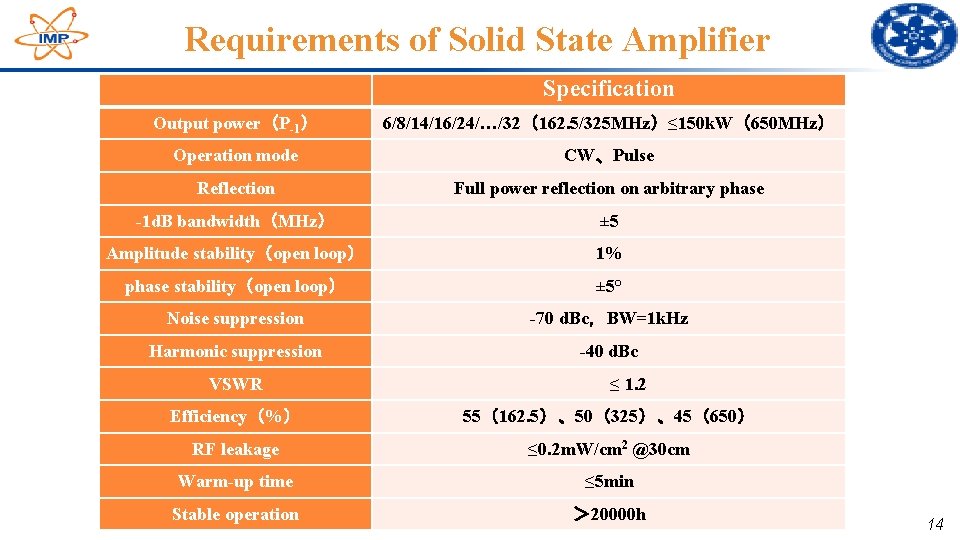
Requirements of Solid State Amplifier Specification Output power(P-1) 6/8/14/16/24/…/32(162. 5/325 MHz)≤ 150 k. W(650 MHz) Operation mode CW、Pulse Reflection Full power reflection on arbitrary phase -1 d. B bandwidth(MHz) ± 5 Amplitude stability(open loop) 1% phase stability(open loop) ± 5° Noise suppression -70 d. Bc,BW=1 k. Hz Harmonic suppression -40 d. Bc VSWR ≤ 1. 2 Efficiency(%) 55(162. 5)、50(325)、45(650) RF leakage ≤ 0. 2 m. W/cm 2 @30 cm Warm-up time ≤ 5 min Stable operation > 20000 h 14
The solution to some problems • SSA for high power cavity • High-precision power detection • Maintainability and yield stress 15
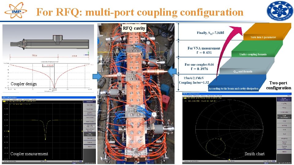
For RFQ: multi-port coupling configuration RFQ cavity Two-port configuration Coupler design Coupler measurement Smith chart 16
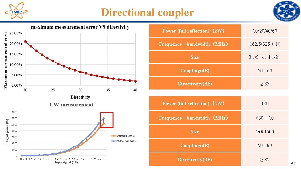
Directional coupler CW measurement Power (full reflection)(k. W) 10/20/40/60 Frequence + bandwidth(MHz) 162. 5/325 ± 10 Size 3 1/8” or 4 1/2” Coupling(d. B) 50 - 60 Directiveity(d. B) ≥ 35 Power (full reflection)(k. W) 180 Frequence + bandwidth(MHz) 650 ± 10 Size WR 1500 Coupling(d. B) 50 - 60 Directiveity(d. B) ≥ 35 Output power (W) 14000 12000 10000 8000 Forward Power 6000 Reflection Power 4000 2000 0 0. 5 1 1. 5 2 2. 5 3 3. 5 4 4. 5 5 5. 5 6 6. 5 7 7. 5 8 8. 5 9 9. 5 10 Input signal (d. B) 17
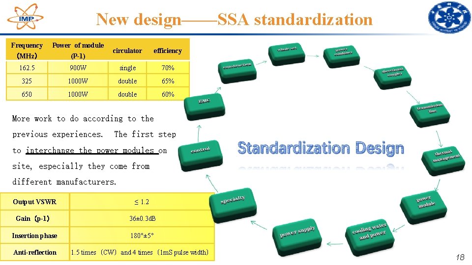
New design——SSA standardization Frequency Power of module (MHz) (P-1) 162. 5 circulator efficiency 900 W single 70% 325 1000 W double 65% 650 1000 W double 60% More work to do according to the previous experiences. The first step to interchange the power modules on site, especially they come from different manufacturers. Output VSWR ≤ 1. 2 Gain(p-1) 36± 0. 3 d. B Insertion phase 180°± 5° Anti-reflection 1. 5 times(CW)and 4 times(1 m. S pulse width) 18
Summary �The specific requirements of SSAs were designed; �A flexible design based on too many power level; �RF structure based on the flexible design; �Every module was restricted with its gain and phase result; �For high power demand on SSA, multi-port coupling method is a good option; �High-precision power detection during the full power reflection; �The solution to maintainability and yield stress. 19
Thank you! 20