Revisiting Transport Congestion Control Jian He UT Austin


![Existing TCP Variants TCP Throughput-Latency Tradeoff Exploration [Remy SIGCOMM’ 13] Datacenter TCP Tail performance[TIMELY Existing TCP Variants TCP Throughput-Latency Tradeoff Exploration [Remy SIGCOMM’ 13] Datacenter TCP Tail performance[TIMELY](https://slidetodoc.com/presentation_image_h/c09b601e7209ba586b6f9c13993e4e23/image-4.jpg)


- Slides: 34

Revisiting Transport Congestion Control Jian He UT Austin 1

Why is Congestion Control necessary? Data Packets Congested Link ACK Ø Congested link vs. reliability: long queuing delay, packet l Ø But, can delay or packet loss always well explain congestio 2

Can we distinguish congestion reasons? Ø Congestion related signals: - packet loss: duplicate ACKs, retransmission timeout (TCP Reno, TCP Cubic) - round-trip delay: TCP packet RTT (TCP Vegas, FAST TCP, Compound TCP) - queue size: explicit congestion notification(ECN) (DCTCP) 3
![Existing TCP Variants TCP ThroughputLatency Tradeoff Exploration Remy SIGCOMM 13 Datacenter TCP Tail performanceTIMELY Existing TCP Variants TCP Throughput-Latency Tradeoff Exploration [Remy SIGCOMM’ 13] Datacenter TCP Tail performance[TIMELY](https://slidetodoc.com/presentation_image_h/c09b601e7209ba586b6f9c13993e4e23/image-4.jpg)
Existing TCP Variants TCP Throughput-Latency Tradeoff Exploration [Remy SIGCOMM’ 13] Datacenter TCP Tail performance[TIMELY SIGCOMM’ 15], New Architectures[R 2 C 2 SIGCOMM’ 15] RDMA[DCQCN SIGCOMM’ 15] Persistently High Performance Large flows[PCC NSDI’ 15] Highly-variant network condition Cellular transport[Verus SIGCOMM’ 15, Sprout NSDI’ 13] Reducing Start-up Delay [Halfback Co. Next’ 15], [RC 3 NSDI’ 14] Performance interference for competing flows Application Heterogeneity[QJUMP NSDI’ 15] 4

TCP Evolution Application-Specific Performance Requirements Application Sensing Layer TCP Networking Sensing Layer IP Link Network Condition Hardware 5

Optimizing Datacenter Transport Tail Performance Mittal, Radhika, et al. "TIMELY: RTT-based congestion control for the datacenter In ACM SIGCOMM 2015. 6

Why does tail performance matter? … Ø TCP Incast: many servers reply the client simultaneously Ø All replies should meet their deadlines. Ø Datacenter transport must deliver high throughput(>>Gbps) and utilization with low delay(<<msec). 7

Hardware Assisted RTT Measurement Why was RTT not widely used? Ø RTT-based congestion control performed poorly at WANs. Ø Highly noisy RTT estimation(system kernel scheduling, etc. Ø Datacenter RTT measurement needs ms-level granularity. Ø Hardware timestamp and hardware acknowledgement can significantly remove noise. 8

RTT As a Congestion Control Signal Multi-bit signal Single-bit signal Ø ECN can not reflect the extent of end-to-end latency inflated by network queuing, due to traffic priorities, multiple congested switches, etc. 9

RTT Correlates with Queuing Delay 10

TIMELY Framework 11

RTT Measurement tsend Serialization Delay RTT tcompletion Propagation & Queuing Delay ACK Turnaround Time Ø One RTT for one segment (NIC Offload) Ø Hardware ACKs make ACK turnaround time ignorable Ø RTT = Propagation + Queuing Delay = tcompletion – tsend – segment_size/NIC_line_rate 12

Transmission Rate Control Message to be sent Segments RTT Estimation Rate Controller Insert delay between segments Transmission Queue Ø Target rate is determined by segment size and delay between segments 13

Rate vs. Window Ø Segment size as high as 64 KB. Ø (32 us RTT x 10 Gbps) = 40 KB window size Ø 40 KB < 64 KB: Window makes no sense 14

Rate Update 15

Evaluation 16

Datacenter Transport for Emerging Architectures Costa, Paolo, et al. "R 2 C 2: A Network Stack for Rack-scale Computers. " In ACM SIGCOMM 2015. 17

Rack-Scale Computing Ø Building Block for future datacenters Ø High BW low latency network Ø Direct-connected topology 18

Rack-Scale Network Topology Ø Distributed switches(each node works as a switch) Ø High path diversities 3 D Torus Fat-tree Topology 19

Broadcasting-Assisted Rack Congestion Control Broadcasting overhead is low(around 1. 3%). Ø Broadcast flow information(e. g. , start time, finish time) Ø Each node has a global view of the network Ø Locally optimize flow rate with the global view 20

Evaluation 21

Congestion Control for RDMA-enabled Datacenters Zhu, Yibo, et al. "Congestion Control for Large-Scale RDMA Deployments. ” In ACM SIGCOMM, 2015. 22

Congestion Spreading in Lossless Networks SE E P PAU E S PAU E A U S US PAUSE PA PAUSE E P US A U SE PA P A U SE SE PAU Ø Port-based congestion control incurs congestion spreading Ø DCQCN: incorporating explicit congestion notification to support flow-based congestion control 23

Wireless Congestion Control Zaki, Yasir, et al. "Adaptive Congestion Control for Unpredictable Cellular Networks. “ In SIGCOMM 2015. 24

What do Cellular Traffic Look Like? Burst Scheduling Competing Traffic 25

What do Cellular Traffic Look Like? Channel Unpredictability 26

Verus Protocol Epoch i+1 Sending window Wi+1 Wi Ø Epoch: a short period of time (e. g. , 5 ms) Ø Sending window is updated at each epoch. Ø Sending window represents the number packets in flight. 27

Verus Overview Delay Estimator: estimate delay in the future based on the changes of delay Delay Profiler: record the relationship of delay-sending window Go to next epoch Window Estimator: estimate the sending window for the next epoch Packet Scheduler: calculate the number packets to be sent in the next epoch 28

Delay Estimation Epoch i-1 Epoch i Dmax, i = alpha x. Dmax, i-1 + (1 -alpha) x. Dmax, i ∆Di = Dmax, i -Dmax, i-1 ∆Di<=0 Estimated Delay Dest, i • ∆Di>0 • Dest, i+1 • Time 29

Window Update Ø Delay-Window Profile: updated based on historical data Ø Each epoch can contribute many points to the profile. Ø Profile is initialized using data in the slow-start phase. 30

Packet Scheduler Epoch i Sending window Wi Epoch i+1 Sending window Wi+1 Ø How many packets to be sent in current epoch? Si+1 = max[0, (Wi+1 + ((2 -n)/(n-1))*Wi)] n is the number of epochs over the current estimated RTT 31

Loss Handling Epoch i Sending window Wi Epoch i+1 Multiplicative Decrease Wi+1 = M * Wi Ø Stop updating delay profile during the loss recovery phase 32

Evaluation 33

Thanks! 34
 Pincuegula
 Jian-yun nie
 Jian-jiun ding
 Jian-jiun ding
 Activities in jian
 Jian sheng wang
 Jian sun
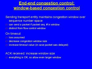
 General principles of congestion control
 In2140
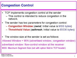
 Tcp congestion control
 Traffic throttling and load shedding
 Principles of congestion control
 Congestion control principles
 Congestion control in virtual circuit
 Udp congestion control
 New reno tcp
 Principles of congestion control
 Congestion control in network layer
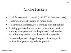
 Choke packets in computer networks
 Segment header
 General principles of congestion control
 Traffic control austin
 Primary and secondary transport
 Primary vs secondary active transport
 Now answer the following questions
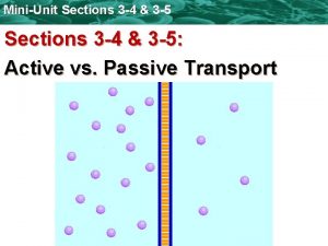
 Active vs passive transport venn diagram
 Endocytosis vs exocytosis
 Primary active transport vs secondary active transport
 Bioflix activity membrane transport active transport
 Active and passive transport
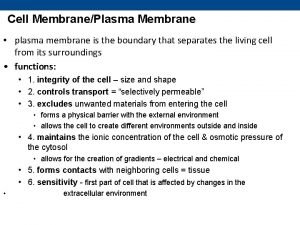
 Selectively permeable definition biology
 Network congestion causes
 Cause and effect introduction
 Conclusion of traffic congestion
 Cvc lung microscopy

