Outline Principles of congestion control TCP congestion control


![Electronic Mail: SMTP [RFC 2821] • uses TCP to reliably transfer outgoing message queue Electronic Mail: SMTP [RFC 2821] • uses TCP to reliably transfer outgoing message queue](https://slidetodoc.com/presentation_image_h2/c8c0ec97aae1a0c9ee65e82ed324fbe5/image-32.jpg)


- Slides: 45

Outline • Principles of congestion control • TCP congestion control 1

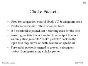
Principles of Congestion Control Congestion: • informally: “too many sources sending too much data too fast for network to handle” • different from flow control! • manifestations: – lost packets (buffer overflow at routers) – long delays (queueing in router buffers) • a top-10 problem! 2

Approaches towards congestion control Two broad approaches towards congestion control: End-end congestion control: Network-assisted congestion control: • no explicit feedback from network • routers provide feedback to end systems • congestion inferred from end-system observed loss, delay • approach taken by TCP – single bit indicating congestion (SNA, DECbit, TCP/IP ECN, ATM) – explicit rate sender should send at 3

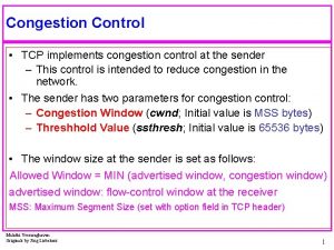
TCP Congestion Control • end-end control (no network assistance) How does sender perceive congestion? • sender limits transmission: • loss event = timeout or 3 duplicate acks Last. Byte. Sent-Last. Byte. Acked Cong. Win • Roughly, rate = Cong. Win Bytes/sec RTT • TCP sender reduces rate (Cong. Win) after loss event three mechanisms: – AIMD • Cong. Win is dynamic, function of perceived network congestion – slow start – conservative after 4

TCP AIMD multiplicative decrease: cut Cong. Win in half after loss event additive increase: increase Cong. Win by 1 MSS every RTT in the absence of loss events: probing Long-lived TCP connection 5

TCP Slow Start • When connection begins, r When connection begins, increase rate Cong. Win = 1 MSS exponentially fast until – Example: MSS = 500 first loss event bytes & RTT = 200 msec – initial rate = 20 kbps • available bandwidth may be >> MSS/RTT – desirable to quickly ramp up to respectable rate 6

TCP Slow Start (more) – double Cong. Win every RTT – done by incrementing Cong. Win for every ACK received • Summary: initial rate is slow but ramps up exponentially fast Host A RTT • When connection begins, increase rate exponentially until first loss event: Host B one segme nt two segme nts four segme nts time 7

Refinement Philosophy: • After 3 dup ACKs: – Cong. Win is cut in half – window then grows linearly • But after timeout event: • 3 dup ACKs indicates network capable of delivering some segments • timeout before 3 dup ACKs is “more alarming” – Cong. Win instead set to 1 MSS; – window then grows exponentially – to a threshold, then grows linearly 8

Refinement (more) Q: When should the exponential increase switch to linear? A: When Cong. Win gets to 1/2 of its value before timeout. Implementation: • Variable Threshold • At loss event, Threshold is set to 1/2 of Cong. Win just before loss event 9

Summary: TCP Congestion Control • When Cong. Win is below Threshold, sender in slow-start phase, window grows exponentially. • When Cong. Win is above Threshold, sender is in congestion-avoidance phase, window grows linearly. • When a triple duplicate ACK occurs, Threshold set to Cong. Win/2 and Cong. Win set to Threshold. • When timeout occurs, Threshold set to Cong. Win/2 and Cong. Win is set to 1 MSS. 10

TCP sender congestion control Event State TCP Sender Action Commentary ACK receipt Slow Start for previously (SS) unacked data Cong. Win = Cong. Win + MSS, If (Cong. Win > Threshold) set state to “Congestion Avoidance” Resulting in a doubling of Cong. Win every RTT ACK receipt Congestion for previously Avoidance unacked data (CA) Cong. Win = Cong. Win+MSS * (MSS/Cong. Win) Additive increase, resulting in increase of Cong. Win by 1 MSS every RTT Loss event detected by triple duplicate ACK SS or CA Threshold = Cong. Win/2, Cong. Win = Threshold, Set state to “Congestion Avoidance” Fast recovery, implementing multiplicative decrease. Cong. Win will not drop below 1 MSS. Timeout SS or CA Threshold = Cong. Win/2, Cong. Win = 1 MSS, Set state to “Slow Start” Enter slow start Duplicate ACK SS or CA Increment duplicate ACK count for segment being acked Cong. Win and Threshold not changed 11

TCP throughput • What’s the average throughout ot TCP as a function of window size and RTT? – Ignore slow start • Let W be the window size when loss occurs. • When window is W, throughput is W/RTT • Just after loss, window drops to W/2, throughput to W/2 RTT. • Average throughout: . 75 W/RTT 12

TCP Fairness goal: if K TCP sessions share same bottleneck link of bandwidth R, each should have average rate of R/K TCP connection 1 TCP connection 2 bottleneck router capacity R 13

Why is TCP fair? Two competing sessions: • Additive increase gives slope of 1, as throughout increases Connection 2 throughput • multiplicative decreases throughput proportionally equal bandwidth share R loss: decrease window by factor of 2 congestion avoidance: additive increase Connection 1 throughput R 14

Fairness (more) Fairness and UDP • Multimedia apps often do not use TCP – do not want rate throttled by congestion control • Instead use UDP: – pump audio/video at constant rate, tolerate packet loss • Research area: TCP friendly Fairness and parallel TCP connections • nothing prevents app from opening parallel cnctions between 2 hosts. • Web browsers do this • Example: link of rate R supporting 9 cnctions; – new app asks for 1 TCP, gets rate R/10 – new app asks for 11 TCPs, gets R/2 ! 15

Midterm Review In class, 3: 30 -5: 00 pm, Mon. 2/9 Closed Book One 8. 5” by 11” sheet of paper permitted (single side)

Lecture 1 • Internet Architecture • Network Protocols • Network Edge • A taxonomy of communication networks

A Taxonomy of Communication Networks • The fundamental question: how is data transferred through net (including edge & core)? • Communication networks can be classified based on how the nodes exchange information: Communication Networks Switched Communication Network Circuit-Switched Communication Network TDM FDM Broadcast Communication Network Packet-Switched Communication Network Datagram Network Virtual Circuit Network

Packet Switching: Statistical Multiplexing 10 Mbs Ethernet A B statistical multiplexing C 1. 5 Mbs queue of packets waiting for output link D E Sequence of A & B packets does not have fixed pattern statistical multiplexing. In TDM each host gets same slot in revolving TDM frame.

Packet Switching versus Circuit Switching • Circuit Switching – Network resources (e. g. , bandwidth) divided into “pieces” for allocation – Resource piece idle if not used by owning call (no sharing) – NOT efficient ! • Packet Switching: – Great for bursty data – Excessive congestion: packet delay and loss – protocols needed for reliable data transfer, congestion control

Datagram Packet Switching • Each packet is independently switched – Each packet header contains destination address which determines next hop – Routes may change during session • No resources are pre-allocated (reserved) in advance • Example: IP networks

Virtual-Circuit Packet Switching • Hybrid of circuit switching and packet switching – All packets from one packet stream are sent along a pre-established path (= virtual circuit) – Each packet carries tag (virtual circuit ID), tag determines next hop • Guarantees in-sequence delivery of packets • However, packets from different virtual circuits may be interleaved

Lecture 2 • Network access and physical media • Internet structure and ISPs • Delay & loss in packet-switched networks • Protocol layers, service models

Internet structure: network of networks • “Tier-3” ISPs and local ISPs – last hop (“access”) network (closest to end systems) – Tier-3: Turkish Telecom, Minnesota Regional Network local ISP Local and tier 3 ISPs are customers of higher tier ISPs connecting them to rest of Internet Tier 3 ISP Tier-2 ISP local ISP Tier-2 ISP Tier 1 ISP Tier-2 ISP local ISP NAP Tier 1 ISP Tier-2 ISP local ISP

Four sources of packet delay • 1. processing: • 2. queueing – check bit errors – time waiting at output link for transmission – determine output link – depends on congestion level of router transmission A propagation B processing queueing

Delay in packet-switched networks 3. Transmission delay: 4. Propagation delay: • R=link bandwidth (bps) • d = length of physical link • L=packet length (bits) • s = propagation speed in medium (~2 x 10⁸ m/sec) • time to send bits into link = L/R transmission A • propagation delay = d/s Note: s and R are very different quantities! propagation B processing queueing

Internet protocol stack • application: supporting network applications – FTP, SMTP, STTP • transport: host-host data transfer – TCP, UDP • network: routing of datagrams from source to destination – IP, routing protocols • link: data transfer between neighboring network elements – PPP, Ethernet • physical: bits “on the wire” application transport network link physical

Application Layer • Principles of app layer protocols • Web and HTTP • FTP • Electronic Mail: SMTP, POP 3, IMAP • DNS • Socket Programming • Web Caching

HTTP connections Nonpersistent HTTP Persistent HTTP • At most one object is sent over a TCP connection. • Multiple objects can be sent over single TCP connection between client and server. • HTTP/1. 0 uses nonpersistent HTTP • HTTP/1. 1 uses persistent connections in default mode • HTTP Message, Format, Response, Methods • HTTP cookies

Response Time of HTTP Nonpersistent HTTP issues: Persistent without pipelining: • requires 2 RTTs per object • client issues new request only when previous response has been received • OS must work and allocate host resources for each TCP connection • but browsers often open parallel TCP connections to fetch referenced objects Persistent HTTP • server leaves connection open after sending response • subsequent HTTP messages between same client/server are sent over connection • one RTT for each referenced object Persistent with pipelining: • default in HTTP/1. 1 • client sends requests as soon as it encounters a referenced object • as little as one RTT for all the referenced objects

FTP: separate control, data connections • FTP client contacts FTP server at port 21, specifying TCP as transport protocol • Client obtains authorization over FTP control connection client TCP control connection port 21 TCP data connection port 20 FTP server • Client browses remote directory • Server opens a second TCP by sending commands over data connection to transfer control connection. another file. • When server receives a • Control connection: “out of command for a file transfer, the band” server opens a TCP data connection to client • FTP server maintains “state”: current directory, earlier • After transferring one file, authentication server closes connection.
![Electronic Mail SMTP RFC 2821 uses TCP to reliably transfer outgoing message queue Electronic Mail: SMTP [RFC 2821] • uses TCP to reliably transfer outgoing message queue](https://slidetodoc.com/presentation_image_h2/c8c0ec97aae1a0c9ee65e82ed324fbe5/image-32.jpg)
Electronic Mail: SMTP [RFC 2821] • uses TCP to reliably transfer outgoing message queue email message from client to server, port 25 • direct transfer: sending user agent user mailbox mail server user agent SMTP server to receiving server mail server user agent SMTP user agent mail server user agent

DNS name servers • no server has all name-to-IP Why not centralize DNS? address mappings • single point of failure • traffic volume • distant centralized database • maintenance doesn’t scale! local name servers: – each ISP, company has local (default) name server – host DNS query first goes to local name server authoritative name server: – for a host: stores that host’s IP address, name – can perform name/address translation for that host’s name

DNS example root name server Root name server: 7 • may not know authoritative name server • may know intermediate name server: who to contact to find authoritative name server 6 2 local name server dns. eurecom. fr 1 8 requesting host 3 intermediate name server dns. nwu. edu 4 5 authoritative name server dns. cs. nwu. edu surf. eurecom. fr www. cs. nwu. edu

DNS: iterated queries recursive query: • puts burden of name resolution on contacted name server • heavy load? iterated query: • contacted server replies with name of server to contact • “I don’t know this name, but ask this server” root name server 2 iterated query 3 4 7 local name server dns. eurecom. fr 1 8 requesting host intermediate name server dns. umass. edu 5 6 authoritative name server dns. cs. umass. edu surf. eurecom. fr gaia. cs. umass. edu

Web caches (proxy server) Goal: satisfy client request without involving origin server • user sets browser: Web accesses via cache • browser sends all HTTP requests to cache – object in cache: cache returns object – else cache requests object from origin server, then returns object to client • Why web caching? origin server HT client. HTTP TP req Proxy server ues t res pon se t s ue q re P nse o T p HT es r TP T H client est u q e Pr T nse o p HT res P T HT origin server

Caching example (3) Install cache origin servers • suppose hit rate is. 4 Consequence • 40% requests will be satisfied almost immediately public Internet • 60% requests satisfied by origin server • utilization of access link reduced to 60%, resulting in negligible delays (say 10 msec) • total delay = Internet delay + access delay + LAN delay =. 6*2 sec +. 6*. 01 secs + milliseconds < 1. 3 secs 1. 5 Mbps access link institutional network 10 Mbps LAN institutional cache

Transport Layer • Transport-layer services • Multiplexing and demultiplexing • Connectionless transport: UDP • Principles of reliable data transfer • TCP – Segment structures – Flow control – Congestion control

Demultiplexing • UDP socket identified by two-tuple: (dest IP address, dest port number) • When host receives UDP segment: – checks destination port number in segment – directs UDP segment to socket with that port number • TCP socket identified by 4 -tuple: – source IP address – source port number – dest IP address – dest port number • recv host uses all four values to direct segment to appropriate socket

UDP: User Datagram Protocol 32 bits source port # dest port # length checksum Application data (message) UDP segment format [RFC 768] Why is there a UDP? • no connection establishment (which can add delay) • simple: no connection state at sender, receiver • small segment header • no congestion control: UDP can blast away as fast as desired

UDP checksum Goal: detect “errors” (e. g. , flipped bits) in transmitted segment Receiver: Sender: • treat segment contents as sequence of 16 -bit integers • checksum: addition (1’s complement sum) of segment contents • sender puts checksum value into UDP checksum field Addition: 1’s complement sum: 0110 0101 1011 0100 • addition of all segment contents + checksum • check if all bits are 1: – NO - error detected – YES - no error detected. But maybe errors nonetheless? More later …. 1’s complement sum: Addition: 0110 0101 0100 1111

Go-Back-N Sender: • k-bit seq # in pkt header • “window” of up to N, consecutive unack’ed pkts allowed • ACK(n): ACKs all pkts up to, including seq # n - “cumulative ACK” – may deceive duplicate ACKs (see receiver) • Single timer for all in-flight pkts • timeout(n): retransmit pkt n and all higher seq # pkts in window

Selective Repeat • receiver individually acknowledges all correctly received pkts – buffers pkts, as needed, for eventual in-order delivery to upper layer • sender only resends pkts for which ACK not received – sender timer for each un. ACKed pkt • sender window – N consecutive seq #’s – again limits seq #s of sent, un. ACKed pkts

Selective repeat: sender, receiver windows

TCP segment structure 32 bits URG: urgent data (generally not used) ACK: ACK # valid PSH: push data now (generally not used) RST, SYN, FIN: connection estab (setup, teardown commands) Internet checksum (as in UDP) source port # dest port # sequence number acknowledgement number head not UA P R S F len used checksum Receive window Urg data pnter Options (variable length) application data (variable length) counting by bytes of data (not segments!) # bytes rcvr willing to accept
 Tcp congestion control
 Tcp congestion control
 Principles of congestion control
 Tcp
Tcp Circumciliary congestion and conjunctival congestion
 General principles of congestion control
 Hop by hop choke packet
 Principles of congestion control in computer networks
 Principles of congestion control
 General principles of congestion control
 Network provisioning in congestion control
 Load shedding in congestion control
 Udp congestion control
 Congestion control in network layer
 What is choke packet
 Sandwich statements
 Tcp error control
 Tcp flow control
 Tcp flow control
 Tcp
Tcp Tcp flow control diagram
 Error control in tcp
 Tcp (transmission control protocol) to protokół
 Tcp sliding window
 Tcp sliding window
 Tcp flow control sliding window
 Network congestion causes
 Cause and effect introduction
 Conclusion of traffic congestion
 Hyperemia and congestion difference
 Eneritis
 Lobar pneumonia
 Carmen bove
 Heart failure cells are seen in lungs
 Congestion
 Pletora mamaria
 Focal crypt abscess
 Nutmeg liver slideshare
 Circumcorneal congestion
 Difference between hyperemia and congestion
 Capacity allocation and congestion management
 Support control and movement lesson outline
 Structure movement and control
 Livelli iso osi e tcp ip
 Twincat modbus tcp configurator
 Tcp 101
