PTS reevaluation project for Czech NPPs Vladislav Pitora

- Slides: 29
PTS re-evaluation project for Czech NPPs Vladislav Pištora, Miroslav Žamboch, Pavel Král, Ladislav Vyskočil Fourth International Conference on Nuclear Power Plant Life Management 23– 27 October 2017 Lyon, France
Introduction q Reactor pressure vessel (RPV) is a key component of nuclear power plant (NPP) that can limit the NPP lifetime. q Radiation embrittlement due to neutron fluence is the most significant aging mechanism for RPV. q For the RPV lifetime assessment, material degradation limit has to be established. q This limit is established on the basis of pressurised thermal shock (PTS) analyses: Ø PTS is an event in NPP that is characterized by rapid cooldown in the primary coolant system with (usually) high primary pressure. Ø PTS analyses are a multidisciplinary task. They consist of a series of thermal hydraulic and structural analyses. q. Two NPPs are operated in the Czech Republic by the ČEZ company: Ø Dukovany NPP (4 units of WWER 440/213 type, start of operation 1985), Ø Temelín NPP (2 units of WWER 1000/320 type, start of operation 2000). q The original assessment of PTS was performed Ø for NPP Dukovany during 1996 – 2004, Ø for NPP Temelín during 2001 – 2004. 1
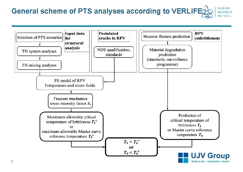
General scheme of PTS analyses according to VERLIFE 2
Normative documents used for the PTS evaluation q Guidelines on Pressurized Thermal Shock Analysis for WWER Nuclear Power Plants, Revision 1, IAEA-EBP-WWER-08 (Rev. 1), IAEA, Vienna, 2006 q Unified Procedure for Lifetime Assessment of Components and Piping in VVER NPPs, VERLIFE, ver. 2003 (the basis for the first PTS Temelín project) q Normative Technical Documentation of Association of Mechanical Engineers (NTD ASI), Section IV, ver. 2004 (Czech equivalent of VERLIFE, ver. 2003) q Unified Procedure for Lifetime Assessment of Components and Piping in VVER NPPs, VERLIFE, ver. 2008 q Normative Technical Documentation of Association of Mechanical Engineers (NTD ASI), Section IV, ver. 2013 (Czech equivalent of VERLIFE, ver. 2008) q IAEA – NULIFE Guidelines for Integrity and Lifetime Assessment of Components and Piping in WWER NPPs During Operation (VERLIFE), to be published q Normative Technical Documentation of Association of Mechanical Engineers (NTD ASI), Section IV, ver. 2017 (based on IAEA – NULIFE VERLIFE) Note: UJV Rez was a co-author of the IAEA, the NTD ASI and the VERLIFE guidelines. 3
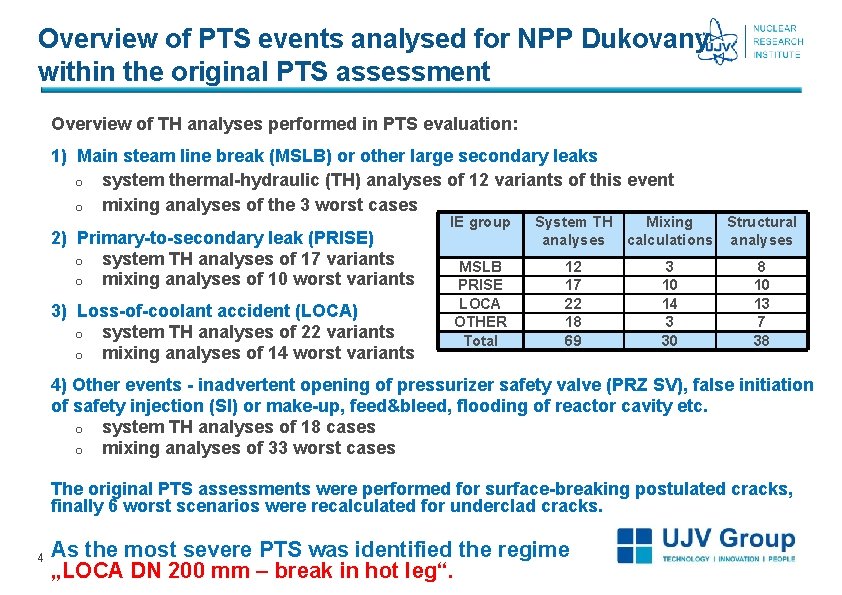
Overview of PTS events analysed for NPP Dukovany within the original PTS assessment Overview of TH analyses performed in PTS evaluation: 1) Main steam line break (MSLB) or other large secondary leaks o system thermal-hydraulic (TH) analyses of 12 variants of this event o mixing analyses of the 3 worst cases 2) Primary-to-secondary leak (PRISE) o system TH analyses of 17 variants o mixing analyses of 10 worst variants 3) Loss-of-coolant accident (LOCA) o system TH analyses of 22 variants o mixing analyses of 14 worst variants IE group MSLB PRISE LOCA OTHER Total System TH Mixing Structural analyses calculations analyses 12 17 22 18 69 3 10 14 3 30 8 10 13 7 38 4) Other events - inadvertent opening of pressurizer safety valve (PRZ SV), false initiation of safety injection (SI) or make-up, feed&bleed, flooding of reactor cavity etc. o system TH analyses of 18 cases o mixing analyses of 33 worst cases The original PTS assessments were performed for surface-breaking postulated cracks, finally 6 worst scenarios were recalculated for underclad cracks. 4 As the most severe PTS was identified the regime „LOCA DN 200 mm – break in hot leg“.
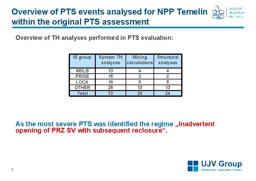
Overview of PTS events analysed for NPP Temelín within the original PTS assessment Overview of TH analyses performed in PTS evaluation: IE group MSLB PRISE LOCA OTHER Total System TH Mixing Structural analyses calculations analyses 13 15 18 26 72 4 2 5 13 24 As the most severe PTS was identified the regime „Inadvertent opening of PRZ SV with subsequent reclosure“. 5
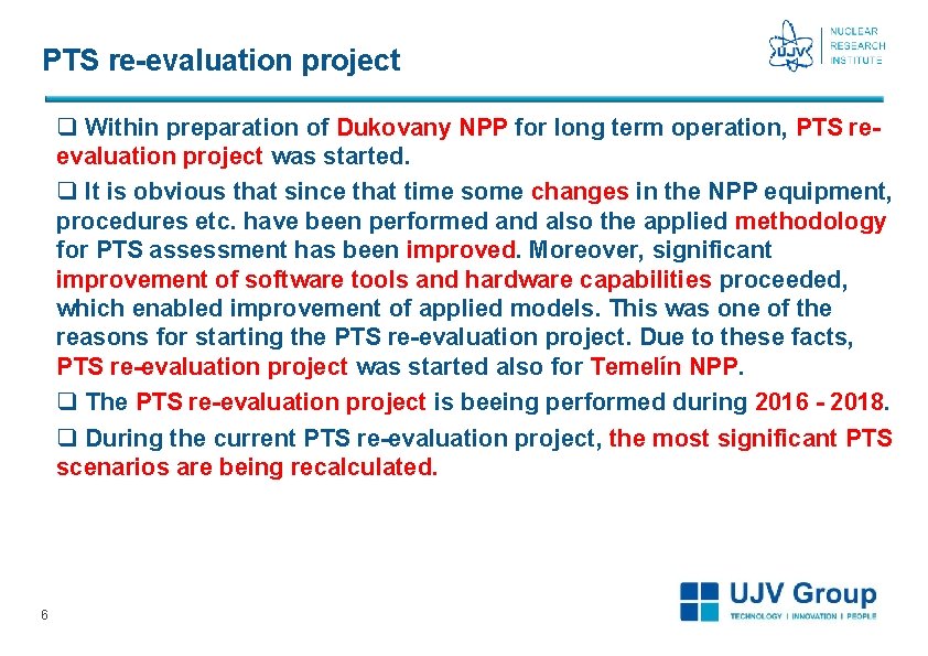
PTS re-evaluation project q Within preparation of Dukovany NPP for long term operation, PTS reevaluation project was started. q It is obvious that since that time some changes in the NPP equipment, procedures etc. have been performed and also the applied methodology for PTS assessment has been improved. Moreover, significant improvement of software tools and hardware capabilities proceeded, which enabled improvement of applied models. This was one of the reasons for starting the PTS re-evaluation project. Due to these facts, PTS re-evaluation project was started also for Temelín NPP. q The PTS re-evaluation project is beeing performed during 2016 - 2018. q During the current PTS re-evaluation project, the most significant PTS scenarios are being recalculated. 6
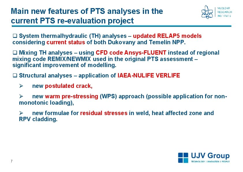
Main new features of PTS analyses in the current PTS re-evaluation project q System thermalhydraulic (TH) analyses – updated RELAP 5 models considering current status of both Dukovany and Temelín NPP. q Mixing TH analyses – using CFD code Ansys-FLUENT instead of regional mixing code REMIX/NEWMIX used in the original PTS assessment – significant improvement of modelling. q Structural analyses – application of IAEA-NULIFE VERLIFE Ø new postulated crack, Ø new warm pre-stressing (WPS) approach (possible application for nonmonotonic loading), Ø new formulae for residual stresses in weld, heat affected zone and RPV cladding. 7
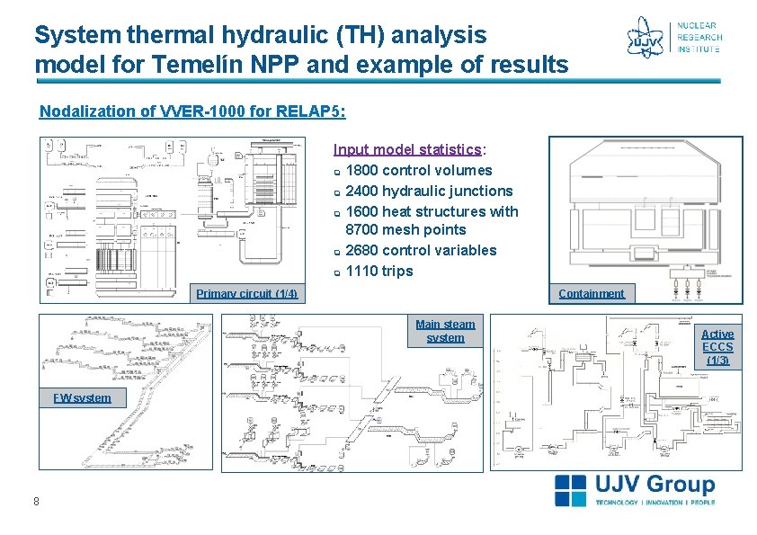
System thermal hydraulic (TH) analysis model for Temelín NPP and example of results Nodalization of VVER-1000 for RELAP 5: Input model statistics: q 1800 control volumes q 2400 hydraulic junctions q 1600 heat structures with 8700 mesh points q 2680 control variables q 1110 trips Containment Primary circuit (1/4) Main steam system FW system 8 Active ECCS (1/3)
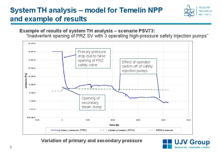
System TH analysis – model for Temelín NPP and example of results Example of results of system TH analysis – scenario PSV 73: “Inadvertent opening of PRZ SV with 3 operating high-pressure safety injection pumps” Primary pressure drop due to false opening of PRZ safety valve Effect of operator switch-off of safety injection pumps Opening of secondary steam dump Variation of primary and secondary pressure 9
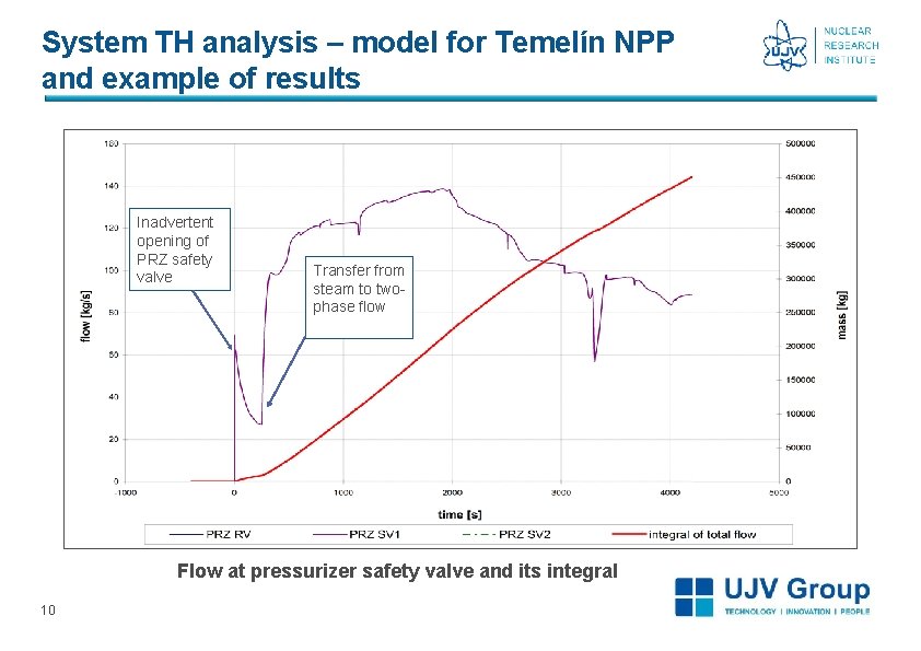
System TH analysis – model for Temelín NPP and example of results Inadvertent opening of PRZ safety valve Transfer from steam to twophase flow Flow at pressurizer safety valve and its integral 10
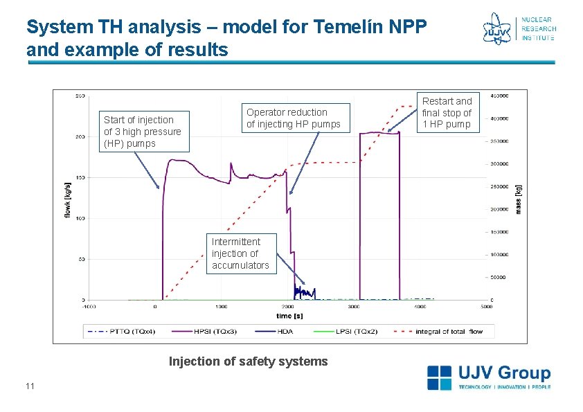
System TH analysis – model for Temelín NPP and example of results Start of injection of 3 high pressure (HP) pumps Operator reduction of injecting HP pumps Intermittent injection of accumulators Injection of safety systems 11 Restart and final stop of 1 HP pump
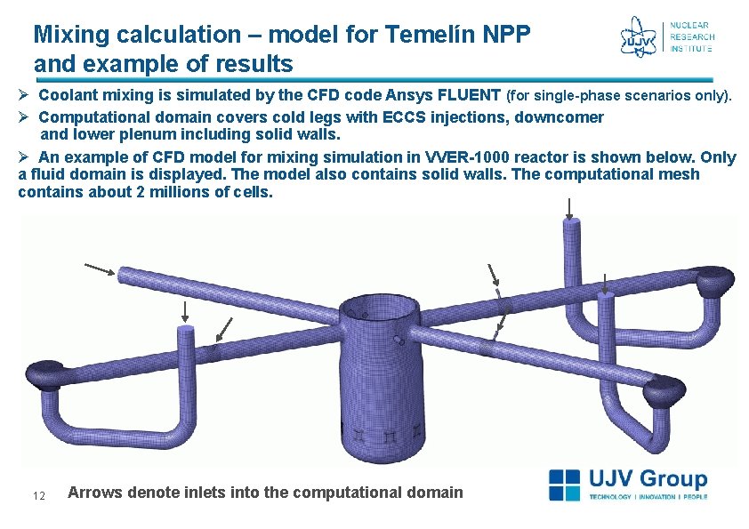
Mixing calculation – model for Temelín NPP and example of results Ø Coolant mixing is simulated by the CFD code Ansys FLUENT (for single-phase scenarios only). Ø Computational domain covers cold legs with ECCS injections, downcomer and lower plenum including solid walls. Ø An example of CFD model for mixing simulation in VVER-1000 reactor is shown below. Only a fluid domain is displayed. The model also contains solid walls. The computational mesh contains about 2 millions of cells. 12 Arrows denote inlets into the computational domain
Mixing calculation – model for Temelín NPP and example of results q Initial and boundary conditions for the mixing simulation in FLUENT are used based on the system TH analysis performed with RELAP 5 code. q Boundary conditions for the CFD simulation are time variations of: Ø mass flow rate and temperature of ECCS injections, Ø mass flow rate and temperature of coolant at cold leg inlets and reactor inlets. q The goal of the simulation is to calculate time evolution of temperature field at wetted surfaces of the reactor pressure vessel wall and cold legs. q The results serve as an input for the subsequent structural analysis. q CFD simulations of mixing for PTS evaluation are computationally expensive. 13
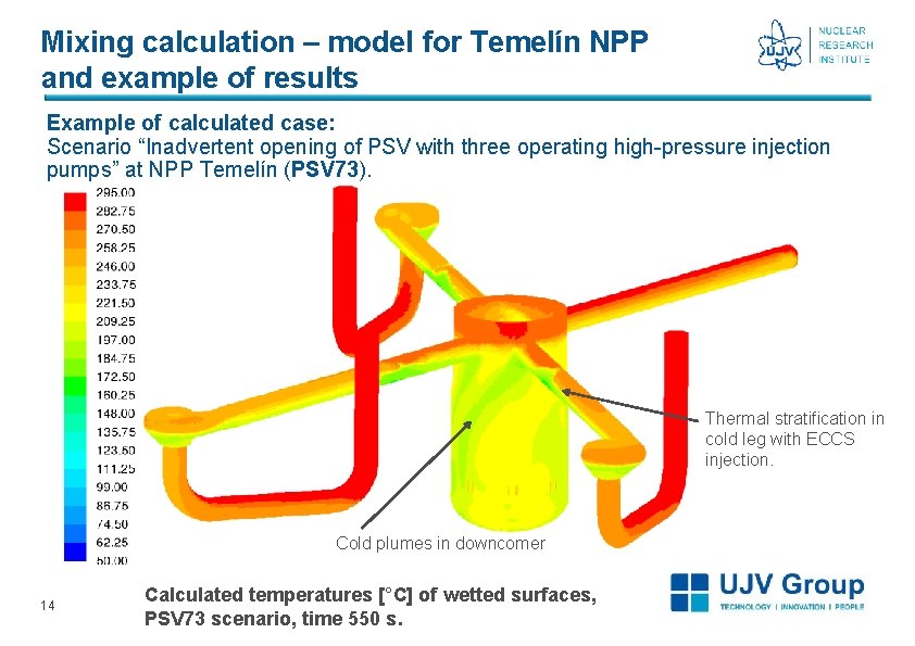
Mixing calculation – model for Temelín NPP and example of results Example of calculated case: Scenario “Inadvertent opening of PSV with three operating high-pressure injection pumps” at NPP Temelín (PSV 73). Thermal stratification in cold leg with ECCS injection. Cold plumes in downcomer 14 Calculated temperatures [°C] of wetted surfaces, PSV 73 scenario, time 550 s.
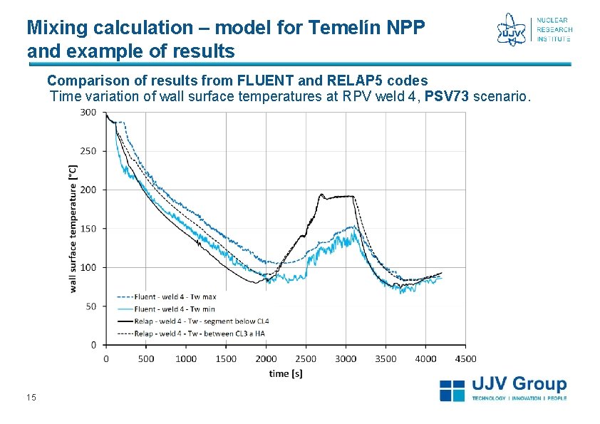
Mixing calculation – model for Temelín NPP and example of results Comparison of results from FLUENT and RELAP 5 codes Time variation of wall surface temperatures at RPV weld 4, PSV 73 scenario. 15
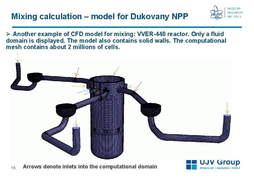
Mixing calculation – model for Dukovany NPP Ø Another example of CFD model for mixing: VVER-440 reactor. Only a fluid domain is displayed. The model also contains solid walls. The computational mesh contains about 2 millions of cells. 16 Arrows denote inlets into the computational domain
Structural analysis – model q Finite element model of cylindrical part of RPV created. q Crack postulated in accordance with VERLIFE: Ø semielliptical underclad crack partially (1 mm) penetrating into cladding, Ø crack postulated in welds No. 3 and 4 (Temelín NPP) or in weld No. 4 (Dukovany NPP) in beltline zone, Ø axial and circumferential orientations of crack, Ø aspect ratios a/c = 0, 3 and 0, 7, Ø crack depth a = 13 + 1 mm (based on NDE qualification requirements and results). q In total, 8 (4) models for 8 (4) postulated crack configurations created for Temelín (Dukovany) NPP. q SYSTUS FEM code used for the analyses. q Heat transfer transient analysis performed as the 1 st step. q Elastic-plastic analysis performed as the 2 nd step for loading by residual stresses, dead weight, inner pressure and transient temperature field. 17
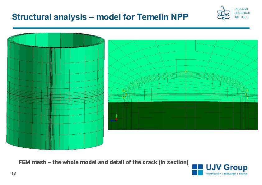
Structural analysis – model for Temelín NPP FEM mesh – the whole model and detail of the crack (in section) 18
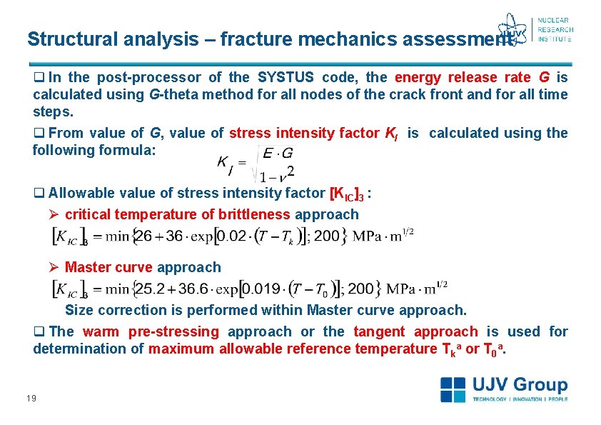
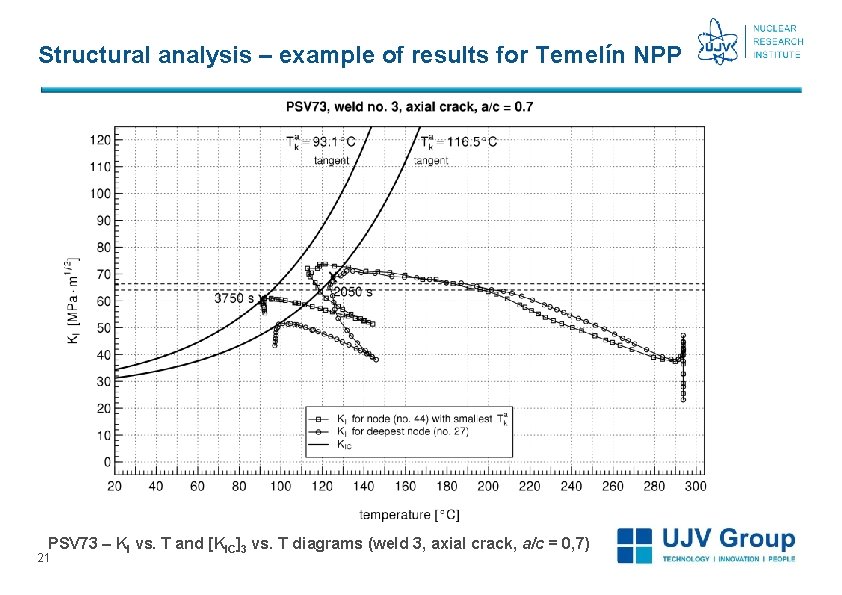
Structural analysis – fracture mechanics assessment q In the post-processor of the SYSTUS code, the energy release rate G is calculated using G-theta method for all nodes of the crack front and for all time steps. q From value of G, value of stress intensity factor KI is calculated using the following formula: q Allowable value of stress intensity factor [KIC]3 : Ø critical temperature of brittleness approach Ø Master curve approach Size correction is performed within Master curve approach. q The warm pre-stressing approach or the tangent approach is used for determination of maximum allowable reference temperature Tka or T 0 a. 19
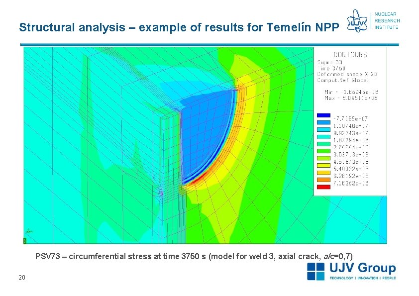
Structural analysis – example of results for Temelín NPP PSV 73 – circumferential stress at time 3750 s (model for weld 3, axial crack, a/c=0, 7) 20
Structural analysis – example of results for Temelín NPP PSV 73 – KI vs. T and [KIC]3 vs. T diagrams (weld 3, axial crack, a/c = 0, 7) 21
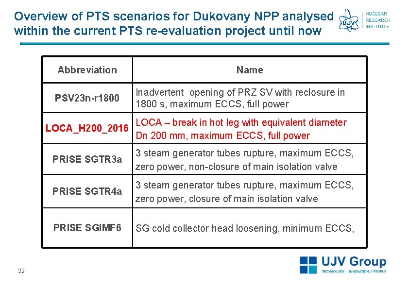
Overview of PTS scenarios for Dukovany NPP analysed within the current PTS re-evaluation project until now Abbreviation 22 Name PSV 23 n-r 1800 Inadvertent opening of PRZ SV with reclosure in 1800 s, maximum ECCS, full power LOCA_H 200_2016 LOCA – break in hot leg with equivalent diameter Dn 200 mm, maximum ECCS, full power PRISE SGTR 3 a 3 steam generator tubes rupture, maximum ECCS, zero power, non-closure of main isolation valve PRISE SGTR 4 a 3 steam generator tubes rupture, maximum ECCS, zero power, closure of main isolation valve PRISE SGIMF 6 SG cold collector head loosening, minimum ECCS,
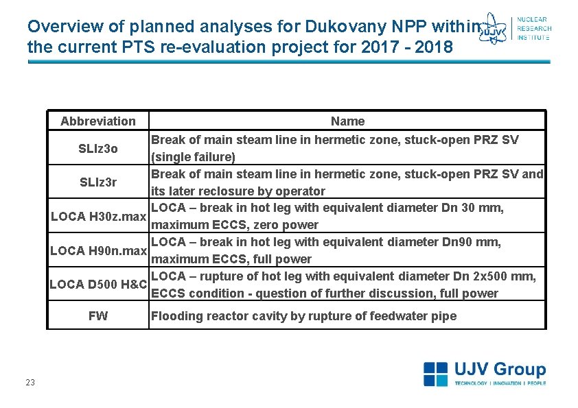
Overview of planned analyses for Dukovany NPP within the current PTS re-evaluation project for 2017 - 2018 Abbreviation Name Break of main steam line in hermetic zone, stuck-open PRZ SV SLIz 3 o (single failure) Break of main steam line in hermetic zone, stuck-open PRZ SV and SLIz 3 r its later reclosure by operator LOCA – break in hot leg with equivalent diameter Dn 30 mm, LOCA H 30 z. maximum ECCS, zero power LOCA – break in hot leg with equivalent diameter Dn 90 mm, LOCA H 90 n. maximum ECCS, full power LOCA – rupture of hot leg with equivalent diameter Dn 2 x 500 mm, LOCA D 500 H&C ECCS condition - question of further discussion, full power FW 23 Flooding reactor cavity by rupture of feedwater pipe
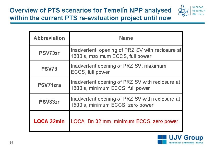
Overview of PTS scenarios for Temelín NPP analysed within the current PTS re-evaluation project until now Abbreviation Name PSV 73 zr Inadvertent opening of PRZ SV with reclosure at 1500 s, maximum ECCS, full power PSV 73 24 Inadvertent opening of PRZ SV, maximum ECCS, full power PSV 71 zra Inadvertent opening of PRZ SV with reclosure at 1500 s, minimum ECCS, full power PSV 83 zr Inadvertent opening of PRZ SV with reclosure at 1500 s, minimum ECCS, zero power LOCA 32 min LOCA Dn 32 mm, minimum ECCS, zero power
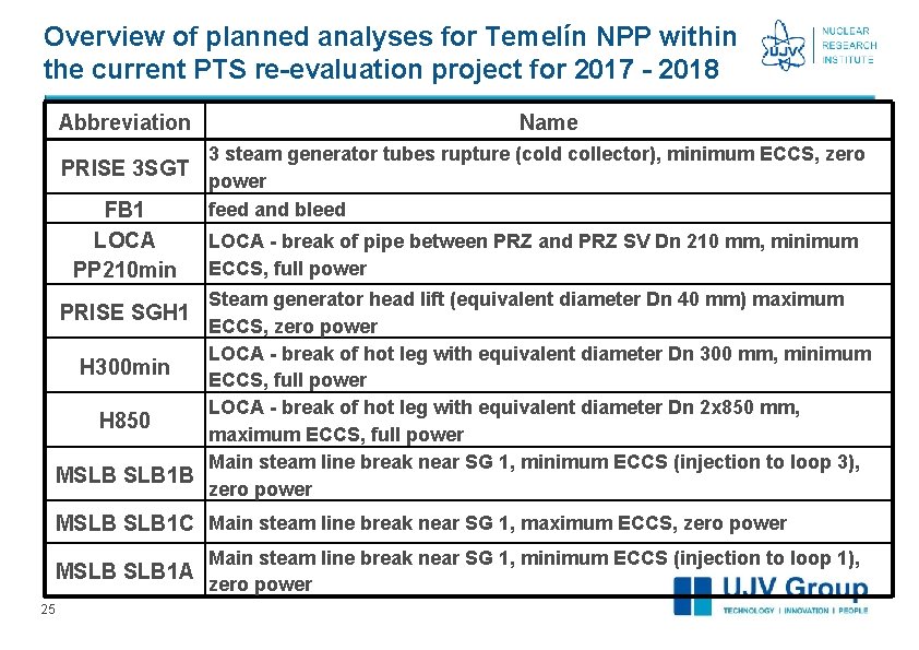
Overview of planned analyses for Temelín NPP within the current PTS re-evaluation project for 2017 - 2018 Abbreviation Name 3 steam generator tubes rupture (cold collector), minimum ECCS, zero PRISE 3 SGT power feed and bleed FB 1 LOCA PP 210 min LOCA - break of pipe between PRZ and PRZ SV Dn 210 mm, minimum ECCS, full power Steam generator head lift (equivalent diameter Dn 40 mm) maximum ECCS, zero power LOCA - break of hot leg with equivalent diameter Dn 300 mm, minimum H 300 min ECCS, full power LOCA - break of hot leg with equivalent diameter Dn 2 x 850 mm, H 850 maximum ECCS, full power Main steam line break near SG 1, minimum ECCS (injection to loop 3), MSLB 1 B zero power PRISE SGH 1 MSLB 1 C Main steam line break near SG 1, maximum ECCS, zero power MSLB 1 A 25 Main steam line break near SG 1, minimum ECCS (injection to loop 1), zero power
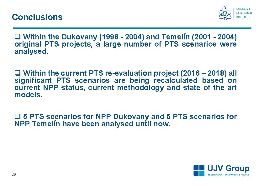
Conclusions q Within the Dukovany (1996 - 2004) and Temelín (2001 - 2004) original PTS projects, a large number of PTS scenarios were analysed. q Within the current PTS re-evaluation project (2016 – 2018) all significant PTS scenarios are being recalculated based on current NPP status, current methodology and state of the art models. q 5 PTS scenarios for NPP Dukovany and 5 PTS scenarios for NPP Temelín have been analysed until now. 26
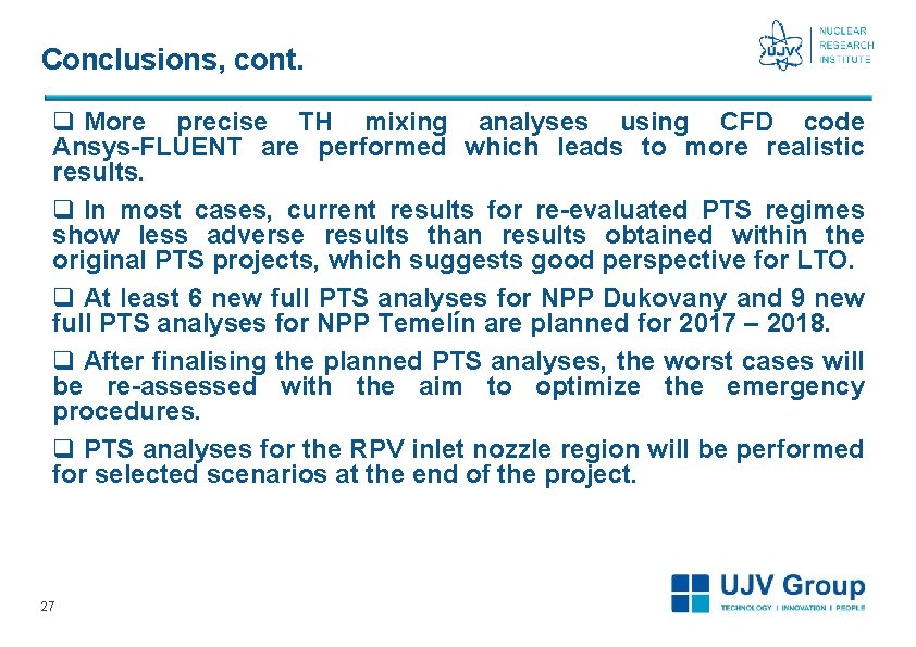
Conclusions, cont. q More precise TH mixing analyses using CFD code Ansys-FLUENT are performed which leads to more realistic results. q In most cases, current results for re-evaluated PTS regimes show less adverse results than results obtained within the original PTS projects, which suggests good perspective for LTO. q At least 6 new full PTS analyses for NPP Dukovany and 9 new full PTS analyses for NPP Temelín are planned for 2017 – 2018. q After finalising the planned PTS analyses, the worst cases will be re-assessed with the aim to optimize the emergency procedures. q PTS analyses for the RPV inlet nozzle region will be performed for selected scenarios at the end of the project. 27
Thank you for your attention 28