Prime Movers Sensors SCADA Dr Haroon Junaidi Prime


- Slides: 27
Prime Movers, Sensors, SCADA Dr. Haroon Junaidi
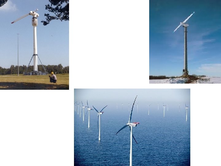
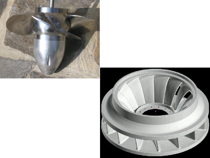
Prime Mover • A device the converts electrical, thermal energy or pressure forces into mechanical energy • Thermal –Mechanical e. g. Steam Engine, IC engine, Turbine • Pressure –Mechanical e. g. Turbine, Propellers, Hydrofoils, Pelton wheels, Attentuator (Pelamis), Hydrofoil (tidal) • Electrical - Mechanical e. g. Electric motor, magnetic rails, Piezoelectric vibration devices
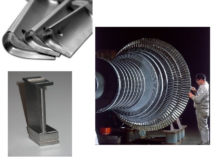
Prime Mover • For turbine type prime mover that extract energy from the fluid by means of a blades, the blade configuration depends upon: • The type of fluid (density), cutting area or size of prime mover, Speed and pressure. • The underlying principle is the same, that is Aerofoil
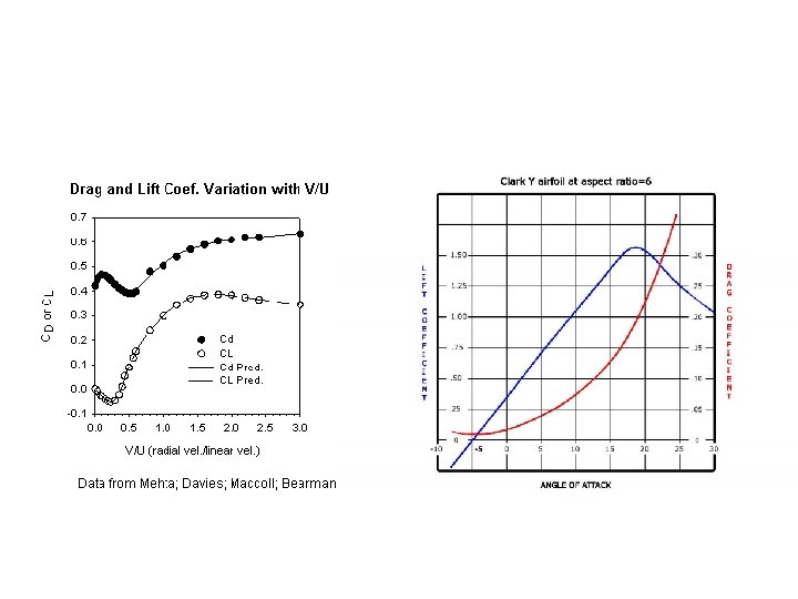
Aerofoil
Drag Force
Shaft Alignment • Shaft alignment is the positioning of the rotational centres of two or more shafts such that they are co-linear when the machines are under normal operating conditions. • There are generally two types of misalignments: – Offset – Angular
Shaft Misalignments
Shaft Misalignment • Bearing failure (up to 50% of bearing failures are due to shaft alignment) • Sealing Failure • Increased stress on shaft/ Shaft fatigue • Constant hammering load on equipment/ Vibration • Waste of energy/ heat build-up • Use alignment tools ( Dial indicator Modern methods include laser shaft alignment) • Elastic couplings
Condition Monitoring • • • Monitoring the temperature levels of various sections of an engine or gas turbine can give indications of component deterioration or advance warning of maintenance requirements A considerable amount of information on plant/ prime mover condition can be obtained by the regular sampling and analysis of engine lubricating oil. The presence of water or other liquid contaminants, or of metallic or nonmetallic solids, provides an indication of excessive wear or leakage, while the condition of the oil itself, such as its acidity and viscosity, gives valuable information on engine condition Monitoring the frequency and amplitude of vibration and noise also gives an indication of condition. On-line condition monitoring is now applied to nearly all gas turbines, to a wide range of the larger engines and wind turbines. The monitoring also extends to the alternators that are connected to these prime movers. Monitoring is generally carried out using sensors with electrical outputs that feed information to a data collection and logging system attached to the plant control system. The data can be extracted and collated for local or offsite review. Condition monitoring will also provide alarms and automatic shutdown instructions to the plant control system
Counter EMF • Counter electromotive force caused by the load effects the speed of the generator prime mover (gas turbine). A governor (speed regulating device) uses a speed sensor and creates a control signal that will adjust the throttle based upon the set point speed. Speed sensors can be mechanical such as centrifugal weights and springs or electrical such as a hall effect transistor and toothed gear. Electrical load such as current and voltage are handled by the voltage regulator. The regulator is designed to keep the output voltage of the generator the same despite speed and electrical load changes. The result is that changes in electrical load are really changes in resistance. A change in resistance across a constant voltage results in a change in current. Changes in current result in changes in magnetism of the generators coils and result in changes in counter elector motive force CMEF. The more CMEF the harder it is to turn the generator. Increase current increases CMEF and causes the generator to slow down. The governor detects the speed drop and opens up the throttle to restore the speed to the set point. Generators designed to be placed in parallel will have a speed droop system which allows some slight drop in throttle setting so that a generator doesn't continue to take additional load from other gens in parallel.
SCADA • Supervisory Control and Data acquisition – It is the automated control technology that merges computers, communication and automation • A few examples of SCADA systems are: – HVAC, Traffic signals, operation of chemical and nuclear plants, electrical power distribution and transmission, mass transit systems, water supply and treatment plants • It usually consists of: • • • Human Machine Interface Computer (Supervisory system) Remote Terminal Units PLC Communications
SCADA • • Human machine interface : -Acts as an interface between human and actual power plant operations • Supervisory system for gathering data of the system and provides feedback to control the system. • RTU: RTUs are basically is used for converting sensor signals to digital signals and directing these signals to the supervisory system. • Programmable logic controller: PLC or programmable logic controller is used for automation of electromechanical operations in a power plant. The main advantage of using PLC is large number of inputs and corresponding outputs can be obtained unlike traditional microprocessors. • Communication infrastructure which acts as midpoint as well as connecting system between supervisory systems and Remote terminal units
SCADA Systems in Renewable • http: //www. youtube. com/watch? v=bfxr 5 Dik d. P 0
Remote Monitoring Sensors Electrical Mechanical optical Chemical • Wireless sensors • Remote sensors will require power preferably without wires • Stand alone systems, power can be taken from a photovoltaic and battery systems • Remote monitoring particularly of off-shore devices is important as it can provide a health check of the device and can save money by increasing time between routine maintenance inspections and detecting faults early
SCADA system at EMEC
Sensors • • Vibration Wind speed Temperature Five main features must be considered when selecting vibration sensors: – – – Measuring range, Frequency range, Accuracy, Transverse sensitivity and ambient conditions.
Vibration sensors • Three types displacement and acceleration, velocity • In general, most high frequency sensors have low sensitivities, and conversely, most high sensitivity sensors have low frequency ranges • Vibration sensors can have from one axis to three axes of measurement, the multiple axes typically being orthogonal to each other • For the ambient conditions, such things as temperature should be considered, as well as the maximum shock and vibration the vibration sensors will be able to handle.
Shaft Deflection • Static Shaft Deflection Although it is unusual for static deflection by itself to be a problem, calculating the static deflection at the seal housing provides an indication of how much of the total deflection is from the overhung load and how much is from other causes. A single stage overhung shaft can be treated like a cantilevered beam. The impeller creates a radial downward force, “F”, at some distance, “L”, from the nearest support bearing. The deflection can be calculated by the equation yc = FL 13/ (3 EI) where • y. C = Shaft deflection at the Impeller centerline • F = Weight of the Impeller • L 1 = Overhang from the closest bearing • E = Modulus of Elasticity for the shaft material • D = Shaft diameter under the sleeve • I = Shaft moment of inertia (0. 049 D 4)
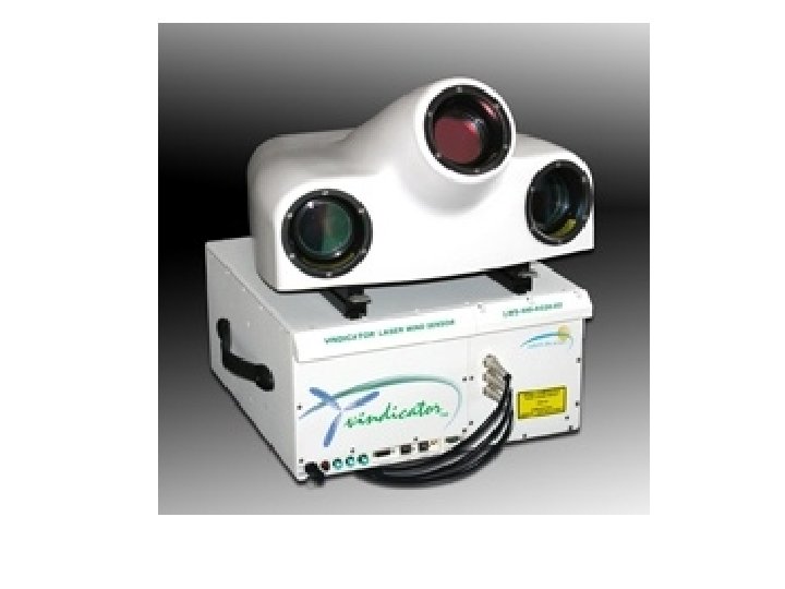
Laser Sensors for Wind Turbine • A new fibre-optic laser system can measure wind speed and direction up to 1000 meters in front of a wind turbine, giving the massive machines enough precious seconds to proactively adapt to gusts and sudden changes in wind direction • Wind turbines lose roughly 1 percent of their operating efficiency for every degree their blades are out of alignment with the oncoming wind. Modern sensors claim that laser system can boost turbine power output by 10 percent by improving orientation accuracy
LIDAR • Light Detection and Ranging • Through scattering of light measures the information. • Lidar is sometimes used on wind farms to more accurately measure wind speeds and wind turbulence. For the future application and an experimental lidar is mounted on a wind turbine rotor to measure oncoming horizontal winds, and proactively adjust blades to protect components and increase power
Courtesy: Monitran Sensors http: //www. directindustry. com/prod/monitran/vibration-sensor-7101 -16744. html
Davis Instrument : Anemometer