Industrial Automation SCADA HMI MX 4 SCADA Software















- Slides: 200

Industrial Automation SCADA & HMI MX 4 SCADA &Software HMI

Industrial Automation SCADA & HMI MX 4 – The Blockview and Structure

Industrial Automation SCADA & HMI MX 4 – The new Visualization - Platform n Support the Melsec series n HMI for stand-alone application n Applicable for e. g. FX/Q 00 JCPU n SCADA – (Supervisory Control And Data Acquisition) for plantwide networkbased applications n. Applicable for e. g. Q 02 CPU upward n Business tools for management reports, analysis n. Plant 2 Sollutions software suite ( up to V 6)

Industrial Automation SCADA & HMI MX 4 – HMI or SCADA, what´s your choise? n MX 4 HMI is a “stand-alone”-product (limitated networkfunctionality) n Constituted for local machine control (one or more PLC´s) n Visualization on HMI-level combined with very good graphics and SCADA functionality e. g Database access n MX 4 SCADA is the choise for applications which need advanced networfunctionality e. g Redundant server or distributed networkfunction (real client-Server architecture)

Industrial Automation SCADA & HMI MX 4 – HMI n Starts with a 100 Tag version n Userfriendly and easy to adabt n Developmentsoftware for free! n Customer pays only for the runtime (Dongle) n Same software like MX 4 SCADA, but only as stand alone version! n Full compatibility n Scalable, if application becomes larger (HMI SCADA) n Fast. Linx included! n Provides, depending on the softwarepackage OPC / Ethernet / MX-Components communication support

Industrial Automation SCADA & HMI MX 4 – HMI Details

Industrial Automation SCADA & HMI MX 4 SCADA - Features and advatages n Strong softwarepackage for visualization and datarecording n Scalable from stand alone version to plantwide applications n Better protection in software- und hardwareinvestment n In a long view a better ratio of Cost / Benefit n The user can see the real process n Many tools available for Datalogging, -analysis und -rescue n Provides full control of the process for the user

Industrial Automation SCADA & HMI MX 4 SCADA - Technical Data n Support Client/Server Networks n Datanintegrity und Realtime-monitoring n Fast datarefresh – 10, 000 tags in 400 ms! n Alarming-functions, Alarmmanagement n Zero downtime by redundant features n Objectbased visualization n Fast. Linx included n MELSOFT compatibel

Industrial Automation SCADA & HMI MX 4 SCADADetails

Industrial Automation SCADA & HMI MX 4 SCADA - Softwarepackages Depending on the needs of the project, seven different (Implementations) can be ordered. n Full Version n Display Client n Internet Display Client n Manager Client (is needed at minimum 1 x time) (controling and monitoring via FTP in WWW) (controling and monitoring via http in WWW) (only monitoring) n Internet Manager Client (only monitoring via FTP in WWW) n Web Manager Client (monitoring via http in WWW) n Web Display Client

Industrial Automation SCADA & HMI MX 4 SCADA – Developmentsoftware for free n By using the developmentversion (without dongle) while runtime is starting, the following have to be noted. n MX 4 starts in Demo Mode! Limitations: n The Demo Mode runs only on stand alone stations! n External communication (to PLC´s) : Timelimit 15 Min! n Internal communication : Timelimit 8 h!

Industrial Automation SCADA & HMI MX 4 SCADA – Softwarepackages – An example 2 redundant Server with 2 Workstations and 1 "View-Only" Workstation Tags: PLC 1: 800 Digital, 300 Analog, 50 Real PLC 2: 750 Digital, 135 Analog, 40 Real PLC 3: 750 Digital, 135 Analog, 40 Real Question: Which types of dongles do we need for this project?

Industrial Automation SCADA & HMI MX 4 SCADA – Softwarepackages – An example 2 redundant Server with 2 Workstations und 1 "View-Only" Workstation Answer: We need 5000 Tags-version dongle! PC 1: 1 MX 4 Full License PC 2: 1 MX 4 Full License PC 3: 1 MX 4 Display Client PC 4: 1 MX 4 Display Client PC 5: 1 MX 4 Manager Client

Industrial Automation SCADA & HMI Fast. Linx – Communication und Datatransfer n Special communication to the MELSEC-World via Fast. Linx n Automatic Tag-Synchronisation between GX IEC Developer und MX 4 saves time during the application development GX IEC Developer Fast. Linx MX 4 SCADA MELSEC PLC MX 4 HMI

Industrial Automation SCADA & HMI Minimum Systemrequirements for MX 4 n Windows NT 4. 0 SP 6, Pentium 500 MHz, 96 MB RAM n Windows NT Server Enterprise SP 5, Pentium 500 MHz, 96 MB RAM n Windows NT Server 4. 0 Terminal Server SP 6, Pentium 500 MHz, 96 MB RAM n Windows 2000 Server SP 3, Pentium 500 MHz, 128 MB RAM n Windows 2000 SP 3, Pentium 500 MHz, 128 MB RAM n Windows XP SP 2 with registry patch, Pentium 500 MHz, 128 MB RAM n Windows 2003, Pentium 500 MHz, 256 MB RAM

Industrial Automation SCADA & HMI Suggested Systemrequirements for MX 4 n Windows NT 4. 0 SP 6, Pentium 500 MHz, 192 MB RAM n Windows NT Server Enterprise SP 5, Pentium 500 MHz, 256 MB RAM n Windows NT Server 4. 0 Terminal Server SP 6, Pentium 500 MHz, 256 MB RAM n Windows 2000 Server SP 3, Pentium 500 MHz, 512 MB RAM n Windows 2000 SP 3, Pentium 500 MHz, 512 MB RAM n Windows XP SP 2 with registry patch, Pentium 500 MHz, 512 MB RAM n Windows 2003, Pentium 500 MHz, 512 MB RAM

Industrial Automation SCADA & HMI Softwareinstalation step by step The softwareinstalation should made always if posible on the main root directory By running MX 4 with Windows XP, you have to prepare XP like the follow manner n Install the servicepack 2. n Disable the internal Firewall to permit communicationerrors. n For die installation of MX 4 service pack the MX 4 Explorer has to be started and closed once before starting the service pack setup.

Industrial Automation SCADA & HMI Softwareinstallation step by step (Setup 1) After starting the setup you have to make the declaration of the installation directory

Industrial Automation SCADA & HMI Softwareinstallation step by step (Setup 2) Fill in the programmfoldername and continue with next. 1. 2.

Industrial Automation SCADA & HMI Softwareinstallation step by step (Setup 3) After installing the MX 4 -Software V 6 Registry patch must be installed. For this start from. . . .

Industrial Automation SCADA & HMI MX 4 -Explorer – The Administrator The MX 4 Explorer is used for the making and the administration of MX 4 Projects.

Industrial Automation SCADA & HMI MX 4 -Explorer Menues File View Tools Help

Industrial Automation SCADA & HMI MX 4 -Projekt Editor the MX 4 Project Editor is used for the declaration of all the non grafical projectdatas. e. g Tags, alarms and communikationsobjects etc.

Industrial Automation SCADA & HMI MX 4 -Project Editor Menues File Edit Communication Tags Tools Alarms Window System Help

Industrial Automation SCADA & HMI MX 4 -Explorer- We create a new project (1) 1. 2. The templatestyle defines the look of the projectpages The choosen resolution must be the same like on the computer on which the project-runtime will be executed.

Industrial Automation SCADA & HMI MX 4 -Explorer- We create a new project (2) Screenresolutions of pages or Templates VGA 640 x 480 Pixel SVGA 800 x 600 Pixel XGA 1024 x 768 Pixel SXGA 1280 x 1024 Pixel User userdefined resolution

Industrial Automation SCADA & HMI MX 4 -Explorer- Wir legen ein neues Projekt an (3) Projectlist The new project These folders belongs to the Project

Industrial Automation SCADA & HMI MX 4 -Projectstructure & Projectfolderobjects (1)

Industrial Automation SCADA & HMI MX 4 - Projectstructure & Projectfolderobjects (2)

Industrial Automation SCADA & HMI Establishing Communication 1. Define with MX-Component the physical communicationpath and the Stationnumber (is needed for the MX 4 Device) 2. (The using of MX-Component is not necessary if there is a direct driver available) 2. Define via Express I/O Device Setup in MX 4 the hardware (Device) and assign the corresponding stationsnumber. 3. (By non using the MX-Component you have to choose the direct driver in the Express I/O Setup) 3. Start Computer Setup

Industrial Automation SCADA & HMI MX-Component - Wizard Communication Setup Utility (1) e. g. serial communication with a Q-CPU Start Wizard

Industrial Automation SCADA & HMI MX-Component - Stationnumber Communication Setup Utility (2) Stationnumber definition (0 -1023) 1. 2.

Industrial Automation SCADA & HMI MX-Component – PC Side Communication Setup Utility (3) 1. 2. 3. Define PC Side

Industrial Automation SCADA & HMI MX-Component – SPS Seite Communication Setup Utility (4) 1. 2. 3. 4. 5. Definition of serial access on the PLC side

Industrial Automation SCADA & HMI MX-Component - Networksupport Communication Setup Utility (5) 1. 2. 3. Networksupport if you are direcly connected to the local station Station Type = Host else Station Type = others Choose PLC mode

Industrial Automation SCADA & HMI MX-Component - Comment Communication Setup Utility (6) Declare a comment for describing this communication-setup 1. Kommentar 2. Ready

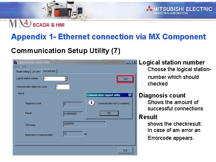
Industrial Automation SCADA & HMI MX-Component – Connection test Communication Setup Utility (7) Logical station number Choose the logical station number which sould be checked. Diagnosis count Shows the amount of successfull connections Result Shows in case of error an error-code.

Industrial Automation SCADA & HMI Setup Communication to the Field MX 4 – Express I/O Device Setup The Express I/O Device Setup assists you in defining the communicationsobjects in MX 4

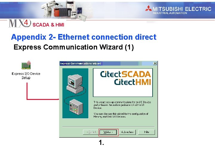
Industrial Automation SCADA & HMI Starting the Express I/O Device Setup Express Communication Wizard (1) 1.

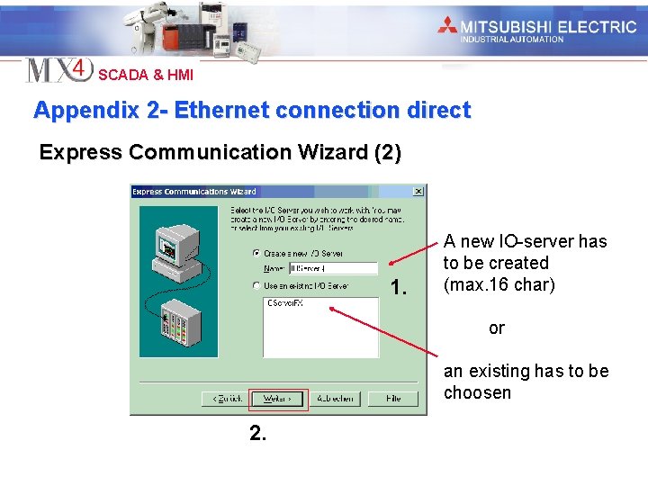
Industrial Automation SCADA & HMI IO Server Express Communication Wizard (2) A new IO Server has to be defined 1. 2. or an existing has to be choosen IOServer: Only one can be online, all the other IO Server have to be offline (standby server).

Industrial Automation SCADA & HMI IO Device Express Communication Wizard (3) 1. A new IO Device has to be defined (max. 16 characters) or an existing has to be choosen 2.

Industrial Automation SCADA & HMI Device Typ Express Communication Wizard (4) Real external Devices: z. B. PLC 1. 2. Virtual Device: Located in the RAM of the local station. (volatile) Virtual Device: Located in the HD of the local station. (non volatile)

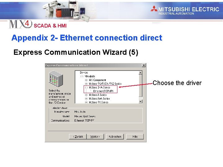
Industrial Automation SCADA & HMI PLC Devicetreiber Express Communication Wizard (5) 1. 2. Choose Devicedriver MX-Component for (Melsecnet, CC-Link) Serial Boards Ethernet Boards

Industrial Automation SCADA & HMI IO Device Adresse (Stationsnummer) Express Communication Wizard (6) 1. Stationnumber of the corresponding Communication setup defined with MX-Component 2.

Industrial Automation SCADA & HMI Externe Tag Datenbanknutzung Express Communication Wizard (7) 1. Mark this field if access to an external common database is needed e. g. Fastlinxs 2.

Industrial Automation SCADA & HMI Kommunikationsaufbau zur Aussenwelt Express Communication Wizard (8) Ready

Industrial Automation SCADA & HMI Übersicht Kommunikationsaufbau

Industrial Automation SCADA & HMI Computer Setup 1. Open MX 4 Explorer 2. Click to My Projects in the projectlist 3. Start Computer Setup

Industrial Automation SCADA & HMI Computer Express Setup - Wizard The Computer Setup Wizard Is used to setup MX 4 and the local station for the project. It has to run once on each station MX 4 is running. Setup Options Express Setup Makes most of the System. Settings autonomic and leaves for the user only a couple of settings to do 1. 2. Das Custom Setup Provides to the user full conntrol over all of the System-Settings

Industrial Automation SCADA & HMI Betriebsarten 1. Station Mode The local station has to be mapped to a Computer type in the stand alone or in the network mode. Depending on this choise the following windows will be different! 2.

Industrial Automation SCADA & HMI Projekt Setup 1. Projectchoise Out of this list you can choose the project you want to run on your local station (Same window for each mode) 2.

Industrial Automation SCADA & HMI IO Server Setup – Stand-Alone-Computer 1. 1. In case were only the default IO Server exists, this window appears without options to set. Ready! 2. In case were more than one IO Server are existing, you can choose one out of the drop down list. Ready!

Industrial Automation SCADA & HMI IO Server Setup – Network Server and Display Client (1) 1. 2. 3. When this local station is an IO Server, you have to set this Option. In this case choose the corresponding IO Server out of the drop down list

Industrial Automation SCADA & HMI IO Server Setup – Network Server and Display Client (2) 1. 2. 3. This option declare whether this station works as an Internet Server or not. In the case of an Internet IO Server the IP Addresses or the Hostnames have to fill in. This window appears only when the local station is defined as IO Server!!

Industrial Automation SCADA & HMI IO Server Setup – Network Server and Display Client (3) This option declare whether this station works as an Alarm Server or not. 1. In the case of Server-Redundancy you have to define whether this Alarm-Server is primary or standby 2. 3.

Industrial Automation SCADA & HMI IO Server Setup – Network Server and Display Client (4) This option declare whether this station works as an Report Server or not. 1. In the case of Server-Redundancy you have to define whether this Report-Server is primary or standby 2. 3.

Industrial Automation SCADA & HMI IO Server Setup – Network Server and Display Client (5) This option declare whether this station works as an Trend Server or not. 1. 2. 3. In the case of Trent-Redundancy you have to define whether this Trent-Server support redundancy (Important for Datasynchronisation)

Industrial Automation SCADA & HMI IO Server Setup – Network Server and Display Client (6) In the case of Server-Redundancy you have to define unique name for the two server (primary and standby ) 1. Inportant for the MX 4 Network! 2. This window appears in the mode Display-Client and Manager Client.

Industrial Automation SCADA & HMI IO Server Setup – Netzwerk Server und Display Client (7) 1. 2. At this point the local Station got an unique name to can be identified in the Windows network. When no name is entered in this field, automaticaly the default name of this station, is the name which coresponds to this station in the local windows network, combinied with a CT before. This window appears in the mode Display-Client and Manager Client.

Industrial Automation SCADA & HMI Computer Setup Termination 1. All modes close with this window

Industrial Automation SCADA & HMI MX 4 – Tags – Processvariabels In MX 4 the variabels are defined as Tag. These are devided in three types Variabel Tags are used for the declaration of processvariabels e. g. I/O´s, Dataregister etc. Trend Tags are used for the declaration of Trenddatas. Trend Tags correspond always to a Variabel Tag. ( Trends) SPC Tags are used for the declaration of statistical process control datas. SPC Tags correspond always to a Variabel Tag

Industrial Automation SCADA & HMI Variable Tags (1) Name of Variabel, max. 32 char. IO Device to which the variabel belongs Variabel-Address, max. 64 char. 1. Physical Unit of the variabel, max. 8 char. Comment max. 48 char. Format of the variabel, max. 8 char.

Industrial Automation SCADA & HMI Variable Tags (2) Add a tag to the database Replace a tag in the database Deletes a tag in the database

Industrial Automation SCADA & HMI Variable Tags - Scaling (3)

Industrial Automation SCADA & HMI Variable Tags - Datatypes

Industrial Automation SCADA & HMI Variabel Tags – Edit with Excel • The file “variable. dbf” can be opened with EXCEL. • Tags can be added. • DON´T USE the “save” instruction of Excels file menue to save the new created file but • Open the file “MX 4/Bin/Save_dbf. xls”. This file start additional macros in Excel which are available in the right mouse menue between these new commands is “Save as DBF”. • Knowledge Base article Q 2599! • The columnwidth may not be changed!

Industrial Automation SCADA & HMI Create a page (1) 1. MX 4 Explorer open 2. Open My Projects in the projectlist 3. Doubleclick on Create a new Page

Industrial Automation SCADA & HMI Create a page (2) 4. Choose template 5. Choose page-style 7. Adds in the template space for a title bar 6. Aktivation of the global pageaktualization

Industrial Automation SCADA & HMI Graphics Builder Is used for the creation and preparation of Pages Templates Symbols Genies Super Genies

Industrial Automation SCADA & HMI Pageproperties – Register General Shows the refreshtime of the page Default: 250 ms Shows the peripherie which logs the keyboardcommands of this page. Specify the area for which this side is released

Industrial Automation SCADA & HMI Pageproperties – Register Appearance Activation of the predefined title bar Definition of the backgroundcolour of the page Definition of the pageresolution in runtime

Industrial Automation SCADA & HMI Pageproperties – Register Keyboard-Commands Entry of the executive command Assigns area an privileges to the command. User with the same profil have access to this command Definition of the Keyboard Sequence which executes the defined command Message which is transmited to the Log-Device when Keyboard-Command is executed

Industrial Automation SCADA & HMI Pageproperties – Register Events Entry of the executive command Definition of the event whitch triggers the executive command

Industrial Automation SCADA & HMI Pageproperties – Register Enviroment In this field you can edit enviroment variables (Virtual Temporary Variables) Access to this variables is only possible over Cicodefunctions. (Cicodeprograming)

Industrial Automation SCADA & HMI Objects are the basic elements for pagecreation Objects are defined over there own properties Object can change their status dynamicaly depending on the value of a variable Size, shape and colour are individually abaptable Objects can be combinied together for creation of more complex functionalities. (Genies) Bitmaps or grafhics can also be inported as objects into a project

Industrial Automation SCADA & HMI Objectproperties – Register Appearance (1) Register for general settings Format of outlines Statical Fillcolour

Industrial Automation SCADA & HMI Objectproperties – Register Appearance (2) Register for 3 D-Settings No effect Shadowed Raised Lowered Embossed

Industrial Automation SCADA & HMI Objectproperties – Register Appearance (3) Register for Visuability Entry for the logical condition Depending on the Status of a variable you can make your object visible or unvisible Clear all your entries

Industrial Automation SCADA & HMI Objectproperties – Horizontal Movement Release of manual Range-Setting Entry of the analog variable or function 0 4000 Min Max Movementvariable Object li. 500 Min re. 500 Max Offset 0 4000

Industrial Automation SCADA & HMI Objectproperties – Vertical Movement Release of manual Range-Setting Entry of the analog variable or function 4000 Max. 500 0 Center Object 0 Min. 500 Movementvariable Offset 4000

Industrial Automation SCADA & HMI Objectproperties – Rotation (1) Release of manual Range-Setting 0 4000 Entry of the analog variable or function 0 Min Max Movementvariable Object li. Min 130° 130 re. Max. 130° 4000

Industrial Automation SCADA & HMI Objectproperties – Rotation (2) The rotationsaxis of an object can be shifted with an offset within 2 dimensions Axis-Offset Variations Custom individually positionin g Express 9 fixed positions

Industrial Automation SCADA & HMI Objectproperties – Horizontal Scaling (1) Release of manual Range-Setting 0 Min 4000 Max Scalingsvariable Width of Object 0 100% Objectaxis Entry of the analog variable or function 0 4000

Industrial Automation SCADA & HMI Objectproperties – Horizontal Scaling (2) Bigger Object Smaller Express 3 fixed positions Custom individually positioning pos. value: shift right neg. value: shift left

Industrial Automation SCADA & HMI Objectproperties – Vertical Scaling (1) Release of manual range-setting 4000 Max. 100% 0 0 Min. 0 Scalingvariable Objectaxis 4000

Industrial Automation SCADA & HMI Objectproperties – Vertical Scaling (2) Bigger Object Smaller Bigger Object Custom individually positioning pos. value: shift right neg. value: shift left

Industrial Automation SCADA & HMI Example Scaling (5) The scalingvariable is filled in both register. Heightchanging • Scaling vertical • Axis bottom Paperroll Paper Widthchanging • Scaling horizontal • Axis right

Industrial Automation SCADA & HMI Objectproperties – Fill (1) Easy changing of fill-colour (Digital variable) Depending on the status of a digital variable, the fill changes his colour

Industrial Automation SCADA & HMI Objectproperties – Fill (2) Multipel fill-colour-changing (Digital variable) Depending on the status of several digital objects, the fill changes his colour. Number of variables is unrestricted

Industrial Automation SCADA & HMI Objectproperties – Fill (3) Multipel fill-colour-changing (Integer variable) Depending on the value of an integer variable, the fill changes his colour

Industrial Automation SCADA & HMI Objectproperties – Fill (4) Multipel fill-colour-changing (Threshold) Depending on the defined thresholds, the object changes his colour. Manualy entry of the data range. When the this option Isn´t enabled, the standart technical values are valid.

Industrial Automation SCADA & HMI Objectproperties – Fill (5) Gradient min. max. The min. and max. value of an integer variable is assigned to two colours. All the values between min and max are interpolated to colours depend on the colourresolution of the grafical system. Manualy entry of the data range. When the this option Isn´t enabled, the standart technical values are valid.

Industrial Automation SCADA & HMI Objectproperties – Fill (6) Levelchanging depending on a integer variable Manualy entry of the data range. When the this option Isn´t enabled, the standart technical values are valid. Filldirection Max. Level

Industrial Automation SCADA & HMI Objectproperties – Input (1) Mouseactivated actions The action is performed When the left mousebutton is released over the object pushed over the object or the user pushes and moves the cursor over the object Repetition rate for these actions. executed action

Industrial Automation SCADA & HMI Objectproperties – Input (2) Keyboard Commands activated actions Key-sequence-editor executed action Area-assignement for the keycommand Privilegeassignment Logmessage sending to the periphery after executing the keycommand

Industrial Automation SCADA & HMI Objectproperties – Slider (1) Horizontal-Slider Variable which corres. Pond to the slider Update for the variable Movingdistance (pixel) in horizontal direction D 0 Slider Max Raw Scale * Pixel Min *see variable tag definition

Industrial Automation SCADA & HMI Objectproperties – Slider (2) Vertical-Slider Variable which corres. Pond to the slider Update for the variable Movingdistance (pixel) in horizontal direction D 0 Min Raw Scale 0 Slider * Max 100 Pixel *see variable tag definition

Industrial Automation SCADA & HMI Objectproperties – Slider (3) Potentiometer D 0 = Min D 0 = Max 90° li. 180° re. Max Raw Scale* 0° 90° angle D 0 Min * see variable tag definition

Industrial Automation SCADA & HMI Objectproperties – Access (1) General Identification No. Of the object Areaassignment for the object Privilegeassignment for the object Log device which receives the log message.

Industrial Automation SCADA & HMI Objectproperties – Access (2) Access disabling Object will be disabled for user with insufficient accessrights when disabled you can choose between Enbossed Greyed Hidden Condition which disables the object

Industrial Automation SCADA & HMI Genies A Genie is compareble to a Functionblock in a PLC It consist out of several objects combined to a new komplex object Genies are saved in a Genie library. All type of graphical objects in MX 4 can be saved with their configurationdatas to the a created Genie Existing Genies can be made wider by using further objects and saved in an existing or an userdefined library.

Industrial Automation SCADA & HMI Paste Genies in pages 5. Fill in the parameter 1. Choose Genie button 3. Choose Genie 4. Confirm to paste the Genie in the page 2. Choose the wanted library

Industrial Automation SCADA & HMI Create a Genie (1) 1. Menue File / New. . Textfield Genie : Pump_east. Library: Pumps 2. 3. The new Genie will be created on a special page 4. Safe in a library

Industrial Automation SCADA & HMI Create a Genie (2) Pump with status- and speeddisplay Instead of a Tag, Substitution- Properties for the Speeddisplaying String-Chains are used. e. g %Speed%. This between %. signs marked variable, will be exchanged automaticaly with a real Tag. Properties for the Statusdisplaying

Industrial Automation SCADA & HMI Create a Genie (3) Saving and creation of a new library With the Filesave as command the new created genie can be stored with a unique name in a preselected library It is also possible to create with the New button, a new library for the genie.

Industrial Automation SCADA & HMI Visualization of digital Variable Digital variables can show their status by displaying a text or changing their appearance (colour, visibility). Example: Input X 0 sould be displayed Symbol Colourchanging Text Visibility

Industrial Automation SCADA & HMI Configuration of a Symbol for DI (Digital Input) 2. 1.

Industrial Automation SCADA & HMI Configuration of a colourchange for DI (Digital Input) 2. Choose in appearance the fill- and outline. Coulor !!! 1.

Industrial Automation SCADA & HMI Configuration of a Text for DI (Digital Input) 2. Choose in appearance the format of the text! 1.

Industrial Automation SCADA & HMI Conditioned Visibility of Objects The properties for the appearance can be set in the General register!!

Industrial Automation SCADA & HMI Visualization of digital Swiches for DO Digital outputs can be switched with button-objects or via an object by setting the input properties. Object Button

Industrial Automation SCADA & HMI Button as digital switch 2. 1.

Industrial Automation SCADA & HMI Example: Shutdown Button 2. 1. By using the switch runtime will shutdown!!

Industrial Automation SCADA & HMI Object as digital switch 2. 1.

Industrial Automation SCADA & HMI Visualization of Analog Tags AI´s (1) Analog Variables could be displayed by Text Numeric Expression Gradient Movement Scaling Min. Max.

Industrial Automation SCADA & HMI Visualization of Analog Tags AI´s (2) Analog Variables could be displayed by Genies Active-X Genies and Active-X Objects provide often Input- and Outputpassibilities on the same object!!!

Industrial Automation SCADA & HMI Analog Tag as Text (AI) Example: Analog 2=30000 Displayed text Textoutput on the respective condition 1. 2. Comparing-Condition

Industrial Automation SCADA & HMI Analog Tag as Numeric Expression (AI) Example: 2. 1.

Industrial Automation SCADA & HMI Analoge Variable als Füllstand Example: 2. Analog 2 defined as level 1. Limits of the levelbeam According to the value of the variable a levelbeam between the two limits will be created.

Industrial Automation SCADA & HMI Analog Variable as Gradient Example: 2. Analog 2 defined as colour 1. Min. Max. Variablevalue According to the value of the variable a colour between the two limits will be created.

Industrial Automation SCADA & HMI Analog Variable as Movementvariable Example: 2. 1. Δl 100 Pixel Min. Max. Variablevaluet A symbol moves depending on a variablevalue between two limits This setting provides bidirectional action (works as input- and output-object)!!!

Industrial Automation SCADA & HMI Analog Variable as Scalingvariable Objektsize Min. Max. Variablevalue An Object changes it´s size depending on the value of a variable between two limits For a symmetrical Scaling, both axis have to be connected to the same variable.

Industrial Automation SCADA & HMI Displaying Analog Data via Genies 2. Label 1. Fontdefinition for the scale Fontdefinition for the label

Industrial Automation SCADA & HMI Displaying Analog Data via Active-X (1) 2. Scale angle Measuring range Scale division Needle format 1.

Industrial Automation SCADA & HMI Displaying Analog Data via Active-X (2) 2. The inputvariable „Analog 1“ is assigned to the internal variable „value“ of the Active-X Object 1.

Industrial Automation SCADA & HMI Input of Analog Data Analog data could be feeded by Numeric expressions Slider(Potentiometer) Genies Active-X Objects

Industrial Automation SCADA & HMI Analog Inputobject as Numeric Expression Example: If the mouse touch the object, a white frame appears. The value can be feeded and confirmed with ENTER #####ENTER Analog 1=Arg. Value 1 2. 1.

Industrial Automation SCADA & HMI Analog Inputobject as Slider (Potentiometer) 2. 1. Slider Draw your Poti or Slider Potentiometer Example D 0 = Min D 0 = Max 0° 0° 90° 180° Definition of the rotation angle (Potentiometer) or of the slidingway (Slider)

Industrial Automation SCADA & HMI Analog Inputobject via PAD (Genie) (1) Example Number PAD 1. ** 3. Genie: Number_Pad Library: keyentry 2. With a mouseclick on the object the Number-pad will appear ** Titel of the object

Industrial Automation SCADA & HMI Analog Inputobject via PAD (Genie) (2) Settings Destination Tag Font of the displayed value Displayed value in runtime Comment Titel of the object

Industrial Automation SCADA & HMI Using Devices (Printer, Databases und Files) A device transfers high-level data (such as a report, command log or alarm log) between Citect. SCADA and other elements (such as a printer, database, RTF file, or ASCII file) in your Citect. SCADA system. Devices are similar to I/O devices in that they both allow Citect SCADA to exchange data with other components in your control and monitoring system.

Industrial Automation SCADA & HMI Using Devices

Industrial Automation SCADA & HMI Applications of Devices (1) MX 4 Alarm Log Device Printer Device Database Report can be sended to different devices

Industrial Automation SCADA & HMI Applications of Devices (2) Device MX 4 Alarm Log Report Printer All of the report are sended to one device

Industrial Automation SCADA & HMI Applications of Devices (3) Device group MX 4 Device Printer 1 2 Database 3 Alarm Log Product Report Shift Report A Device group allows the distribution of datas to several devices

Industrial Automation SCADA & HMI Einsatzmöglichkeiten von Peripherien (4) Datenbank 1 Peripherie MX 4 Peripherie Datenbank 2 Datas could be imported via Devices

Industrial Automation SCADA & HMI Configuration of Devices e. g Printer Destination of data LPT 1: * Dataformat of the print: Date (10 char) Textfield (32 char) COM 2: * Datei. txt Datei. dbf In case of networkprinter fill in the printername, In case of local printer Fill in the portname e. g LPT 1: oder COM 1: Devicetypes *by declaring of a local printerdevice set „: “ after the portmame, otherwise MX 4 is going to interpret the entry as file!!!!!

Industrial Automation SCADA & HMI Configuration of Devices e. g ASCII-file -1 makes the entry to The end of the file Dataformat of the print: Date (10 char) Time (5 char) Textfield (32 char) Devicetype Data Destinatio [DATA] C: Program FilesMX 4SCADAData The path is specified on the second last page of the Custom Computer Setup!

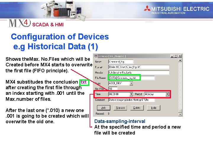
Industrial Automation SCADA & HMI Configuration of Devices e. g Historical Data (1) Shows the. Max. No. Files which will be Created before MX 4 starts to overwrite the first file (FIFO principle). MX 4 substitudes the conclusion. txt after creating the first file through an index starting with. 001 until the Max. number of files. After the last one (*. 010) a new one. 001 is going to be created which will overwrite the old one. Data-sampling-interval At the specified time and period a new file will be created

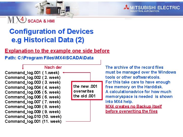
Industrial Automation SCADA & HMI Configuration of Devices e. g Historical Data (2) Explanation to the example one side before Path: C: Program FilesMX 4SCADAData Nach der Command_log. 001 ( 1. week) Command_log. 002 ( 2. week) Command_log. 003 ( 3. week) Command_log. 004 ( 4. week) Command_log. 005 ( 5. week) Command_log. 006 ( 6. week) Command_log. 007 ( 7. week) Command_log. 008 ( 8. week) Command_log. 009 ( 9. week) Command_log. 010 (10. week) Command_log. 001 (11. week) the new. 001 overwrites the old. 001 The archive of the record files must be managed over the Windows tools or other softwaretools. For this take care to have enough free memory on the Harddisk. A calculationadvice for how much memoryspace is needed is shown Into MX 4 help. MX 4 creates no Backup itself before overwriting the files

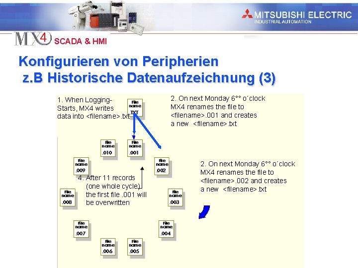
Industrial Automation SCADA & HMI Konfigurieren von Peripherien z. B Historische Datenaufzeichnung (3) 1. When Logging. Starts, MX 4 writes data into <filename>. txt 4. After 11 records (one whole cycle) the first file. 001 will be overwritten 2. On next Monday 6°° o´clock MX 4 renames the file to <filename>. 001 and creates a new <filename>. txt 2. On next Monday 6°° o´clock MX 4 renames the file to <filename>. 002 and creates a new <filename>. txt

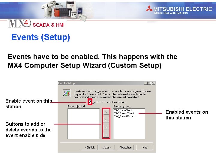
Industrial Automation SCADA & HMI Events are needed to trigger functions, commands or other actions in MX 4 Events may executed Automaticaly at a defined time and period Automaticaly when a defined condition becomes true Automaticaly at a combination of both prior conditions

Industrial Automation SCADA & HMI Events (Setup) Events have to be enabled. This happens with the MX 4 Computer Setup Wizard (Custom Setup) Enable event on this station Enabled events on this station Buttons to add or delete evends to the event enable side

Industrial Automation SCADA & HMI Defining events Name (16 char) Time condition (32 char) Triggercondition (64 char) Comment (48 char) Triggered Action (64 char) Variation of execution: a. b. c. Time Trigger Time and Trigger

Industrial Automation SCADA & HMI Trends (Logging and Trending) MX 4 offers various types of trends for logging and trendinding datas combinied with integrated print and exportfunctions! Types of trend • Periodical Trend (with or without Trigger) • Eventtriggered Trend • A combination of both MX 4 provides unrestricted datacollection (restriction only through the harddisksize) Collected datas may be savefed to external storagemedia without interrupting the process Ready trendtemplates reduce the developmenttime for trendpages to „ 0“

Industrial Automation SCADA & HMI Trendtypes – TRN_PERIODIC Datasampling happens within a fixed samlinginterval. The datasampling can be connected to a triggerconnection

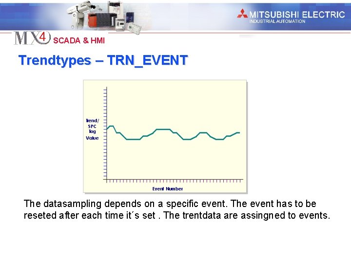
Industrial Automation SCADA & HMI Trendtypes – TRN_EVENT The datasampling depends on a specific event. The event has to be reseted after each time it´s set. The trentdata are assingned to events.

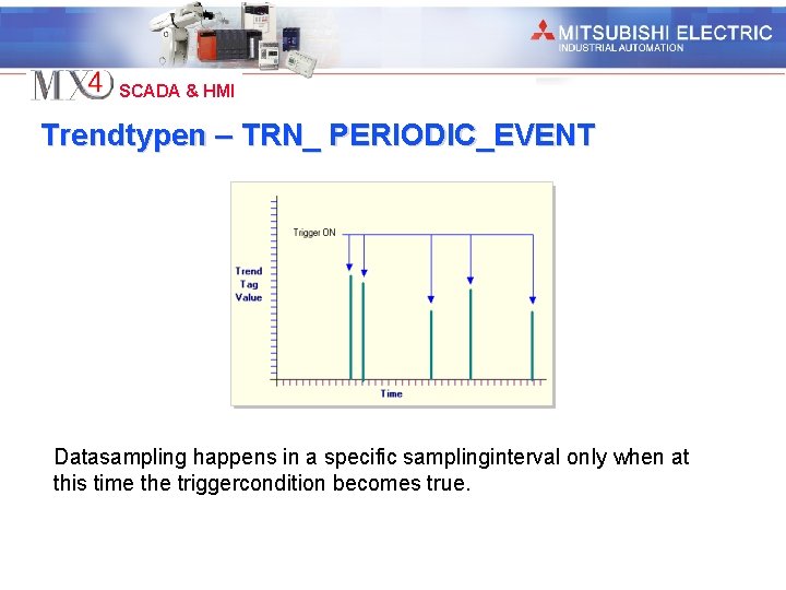
Industrial Automation SCADA & HMI Trendtypen – TRN_ PERIODIC_EVENT Datasampling happens in a specific samplinginterval only when at this time the triggercondition becomes true.

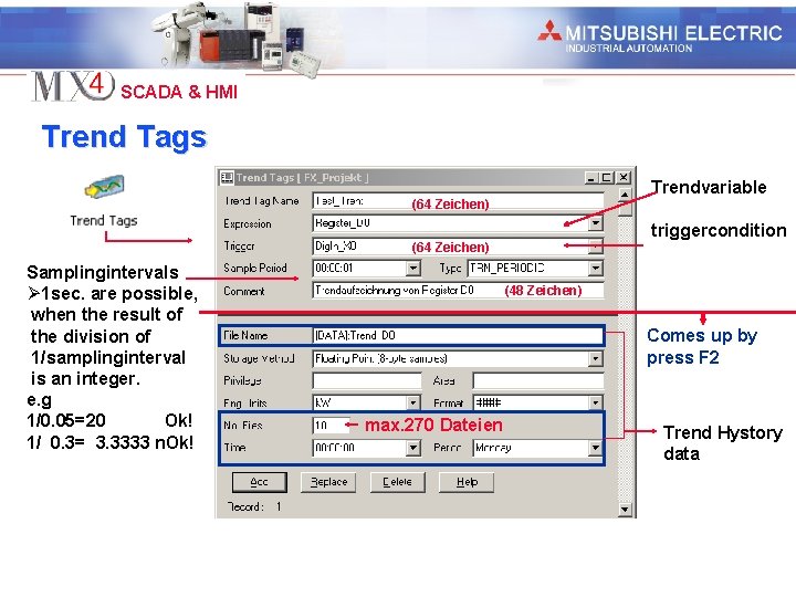
Industrial Automation SCADA & HMI Trend Tags Trendvariable (64 Zeichen) triggercondition (64 Zeichen) Samplingintervals Ø 1 sec. are possible, when the result of the division of 1/samplinginterval is an integer. e. g 1/0. 05=20 Ok! 1/ 0. 3= 3. 3333 n. Ok! (48 Zeichen) Comes up by press F 2 max. 270 Dateien Trend Hystory data

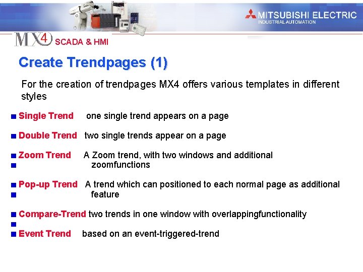
Industrial Automation SCADA & HMI Create Trendpages (1) For the creation of trendpages MX 4 offers various templates in different styles Single Trend one single trend appears on a page Double Trend two single trends appear on a page Zoom Trend A Zoom trend, with two windows and additional zoomfunctions Pop-up Trend A trend which can positioned to each normal page as additional feature Compare-Trend two trends in one window with overlappingfunctionality Event Trend based on an event-triggered-trend

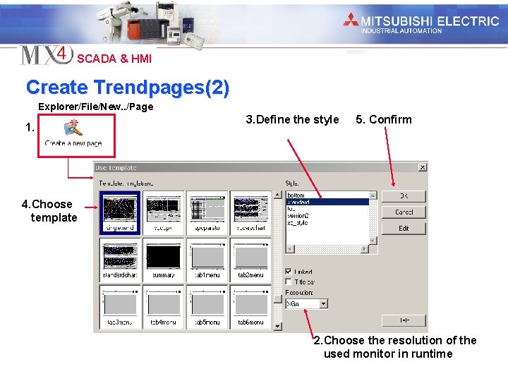
Industrial Automation SCADA & HMI Create Trendpages(2) Explorer/File/New. . /Page 1. 3. Define the style 5. Confirm 4. Choose template 2. Choose the resolution of the used monitor in runtime

Industrial Automation SCADA & HMI Alarms (Alarmtypes) (1) MX 4 support two alarmtypes Alarmtypes • Hardware Alarms MX 4 execute continiously internal hardwarecheckroutines of all connected devices. Alarm becomes automaticaly registated. These properties are fixed and needs no further configuration. • Configurated Alarms Are all these alarms which come out of the process and have to be configured manualy.

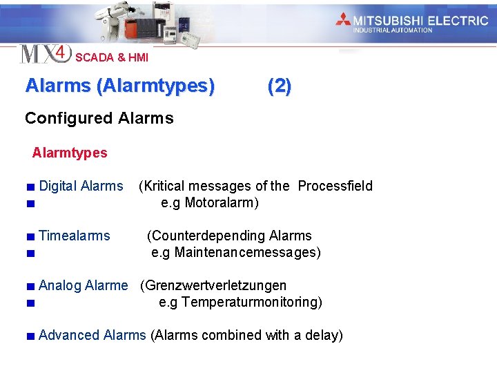
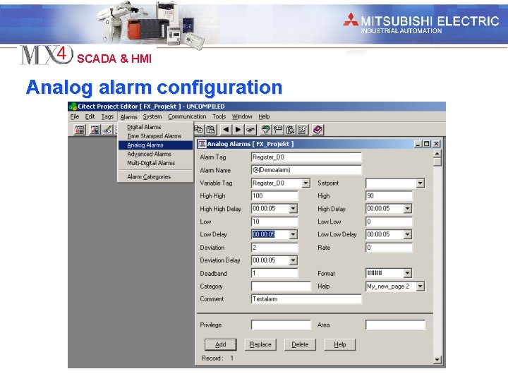
Industrial Automation SCADA & HMI Alarms (Alarmtypes) (2) Configured Alarms Alarmtypes Digital Alarms Timealarms (Kritical messages of the Processfield e. g Motoralarm) (Counterdepending Alarms e. g Maintenancemessages) Analog Alarme (Grenzwertverletzungen e. g Temperaturmonitoring) Advanced Alarms (Alarms combined with a delay)

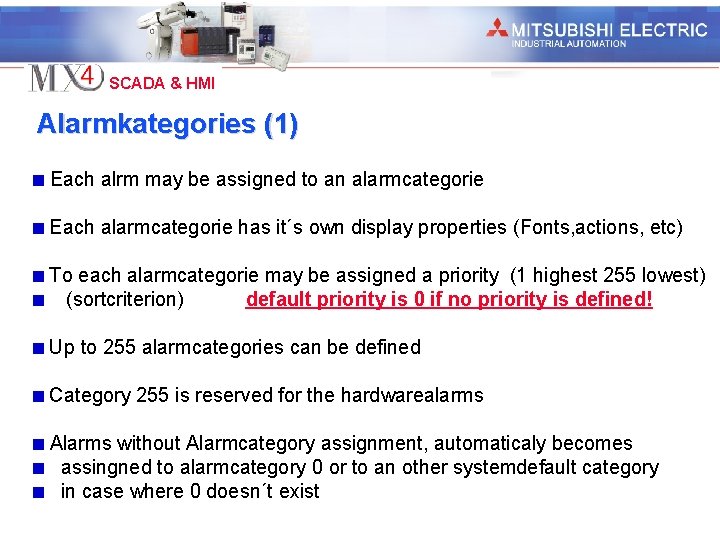
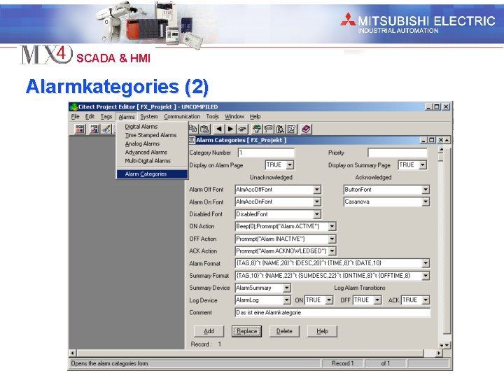
Industrial Automation SCADA & HMI Alarmkategories (1) Each alrm may be assigned to an alarmcategorie Each alarmcategorie has it´s own display properties (Fonts, actions, etc) To each alarmcategorie may be assigned a priority (1 highest 255 lowest) (sortcriterion) default priority is 0 if no priority is defined! Up to 255 alarmcategories can be defined Category 255 is reserved for the hardwarealarms Alarms without Alarmcategory assignment, automaticaly becomes assingned to alarmcategory 0 or to an other systemdefault category in case where 0 doesn´t exist

Industrial Automation SCADA & HMI Alarmkategories (2)

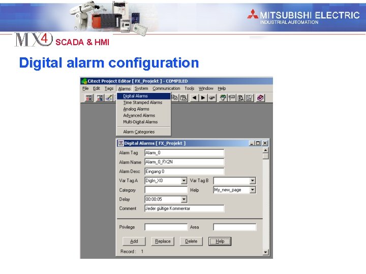
Industrial Automation SCADA & HMI Digital alarm configuration

Industrial Automation SCADA & HMI Analog alarm configuration

Industrial Automation SCADA & HMI Advanced alarms configuration

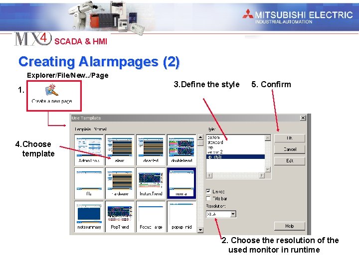
Industrial Automation SCADA & HMI Creating Alarmpages (1) For the creation of alarmpages MX 4 offers various templates in different styles Hardware This page displays all the alarm coming from the connected hardwaredevices. ( field and system) Alarm This page shows all the actual alarms Disable This page shows all the disabled alarms Alarm Summary This page shows all the alarms in chronologikal sequence

Industrial Automation SCADA & HMI Creating Alarmpages (2) Explorer/File/New. . /Page 1. 3. Define the style 5. Confirm 4. Choose template 2. Choose the resolution of the used monitor in runtime

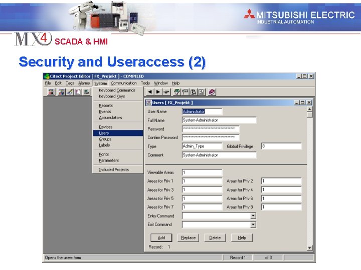
Industrial Automation SCADA & HMI Security and Useraccess (1) Each object may be assigned to an area MX 4 allows the definition of 255 areas Priviliges provide a hierarhical access structure in each area 8 priviligecategories are existing Privilige 1 is the lowest and privilige 8 the highest A defined user got from his administrator access for areas and priviliges for these To acknowledge alarms privilige 1 is at minimum necessary

Industrial Automation SCADA & HMI Security and Useraccess (2)

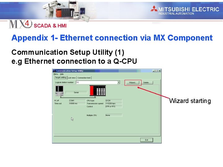
Industrial Automation SCADA & HMI Appendix 1 - Ethernet connection via MX Component Communication Setup Utility (1) e. g Ethernet connection to a Q-CPU Wizard starting

Industrial Automation SCADA & HMI Appendix 1 - Ethernet connection via MX Component Communication Setup Utility (2) Fill in stationsnumber (0 -1023) 1. 2.

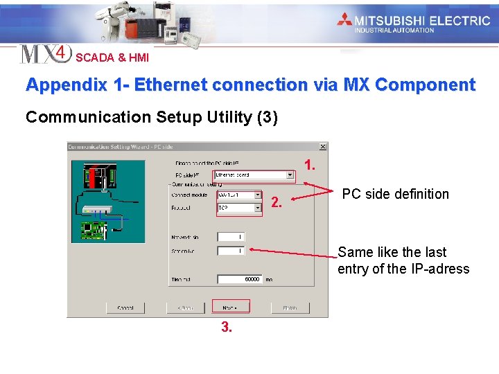
Industrial Automation SCADA & HMI Appendix 1 - Ethernet connection via MX Component Communication Setup Utility (3) 1. 2. PC side definition Same like the last entry of the IP-adress 3.

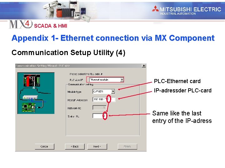
Industrial Automation SCADA & HMI Appendix 1 - Ethernet connection via MX Component Communication Setup Utility (4) PLC-Ethernet card IP-adressder PLC-card Same like the last entry of the IP-adress

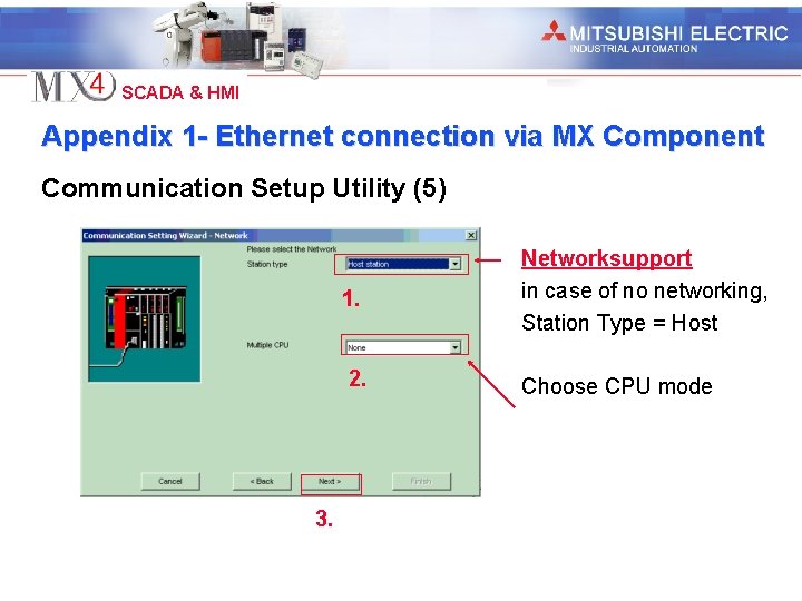
Industrial Automation SCADA & HMI Appendix 1 - Ethernet connection via MX Component Communication Setup Utility (5) 3. 1. Networksupport in case of no networking, Station Type = Host 2. Choose CPU mode

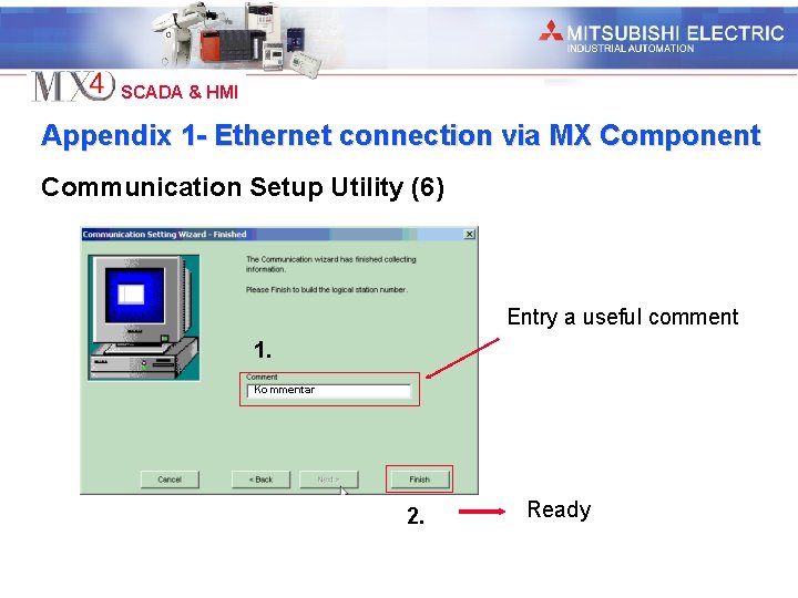
Industrial Automation SCADA & HMI Appendix 1 - Ethernet connection via MX Component Communication Setup Utility (6) Entry a useful comment 1. Kommentar 2. Ready

Industrial Automation SCADA & HMI Appendix 1 - Ethernet connection via MX Component Communication Setup Utility (7) Logical station number Choose the logical stationnumber which should checked Diagnosis count Shows the amount of successful connections Result shows the checkresult. In case of am error an Errorcode appears.

Industrial Automation SCADA & HMI Appendix 2 - Ethernet connection direct Express Communication Wizard (1) 1.

Industrial Automation SCADA & HMI Appendix 2 - Ethernet connection direct Express Communication Wizard (2) 1. A new IO-server has to be created (max. 16 char) or an existing has to be choosen 2.

Industrial Automation SCADA & HMI Appendix 2 - Ethernet connection direct Express Communication Wizard (3) 1. A new IO-device has to be created (max. 16 char) or an existing has to be choosen 2.

Industrial Automation SCADA & HMI Appendix 2 - Ethernet connection direct Express Communication Wizard (4) Real external device: e. g. PLC 1. 2. Virtual Device: Is simulated on the RAM and is volatile Virtual Device: Is simulated on the harddisk and is no volatile

Industrial Automation SCADA & HMI Appendix 2 - Ethernet connection direct Express Communication Wizard (5) Choose the driver

Industrial Automation SCADA & HMI Appendix 2 - Ethernet connection direct Express Communication Wizard (6) IP-adress port and protocol of the PLC-card have to filled in Portnumber when TCP=5002 UDP=5001

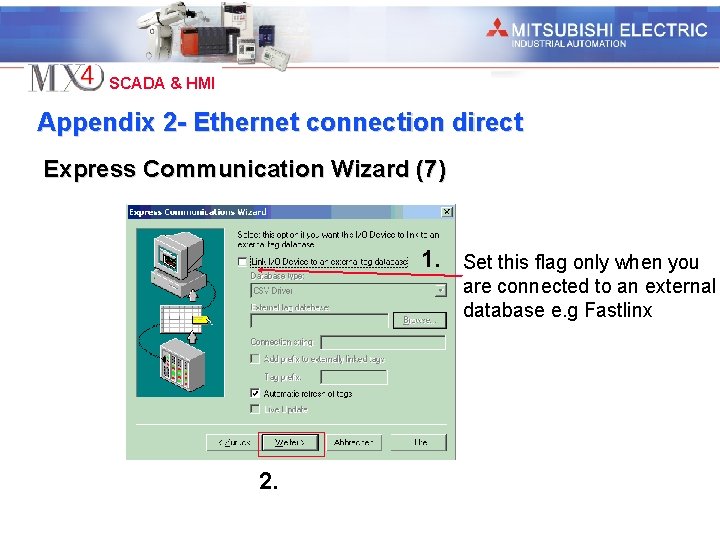
Industrial Automation SCADA & HMI Appendix 2 - Ethernet connection direct Express Communication Wizard (7) 1. Set this flag only when you are connected to an external database e. g Fastlinx 2.

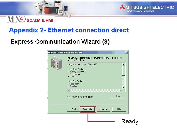
Industrial Automation SCADA & HMI Appendix 2 - Ethernet connection direct Express Communication Wizard (8) Ready

Industrial Automation SCADA & HMI Appendix 3 - Fastlinx Configuration (1) 1. Create a GID-project with a new global variable list 2. Create a new Fastlinx database 3. Mark in the GID-project global variable list each variable for transfer to Fastlinx and save the GID-project 4. Create a new MX 4 project (MX 4 projectname = Fastlinx Databasename) 5. Create an I/O Device (I/O Devicename = GID projectname) 6. Start Express IO Device Setup (secondlast window) and mark link to an external database 6. Choose Database Type => Mitsubishi Fastlinx 7. Choose with the browser the external Tag Database 8. Finish Express IO Device Setup

Industrial Automation SCADA & HMI Appendix 3 - Fastlinx Configuration (2) 9. 10. 11. 8. 9. 10. To add tags from MX 4 to Fastlinx set linking of the I/O Device on false. This separate the IO-Device from the database (press F 2 with selected IO-Device ) Create the new tags and add these to the database Set linking of the I/O Device on true Open the GID project and save it once Tags from GID->MX 4 Create the new global variables, mark these for transfer and save the project once.

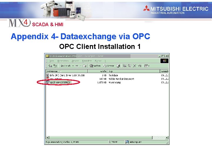
Industrial Automation SCADA & HMI Appendix 4 - Dataexchange via OPC Client Installation 1

Industrial Automation SCADA & HMI Appendix 4 - Dataexchange via OPC Client Installation 2

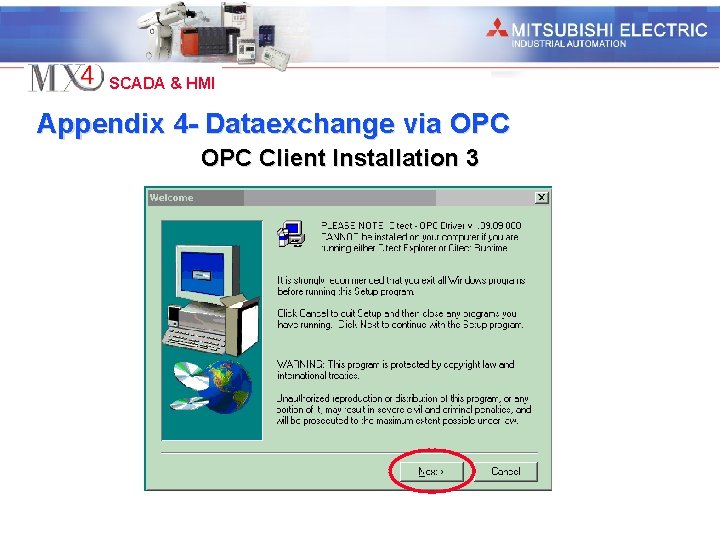
Industrial Automation SCADA & HMI Appendix 4 - Dataexchange via OPC Client Installation 3

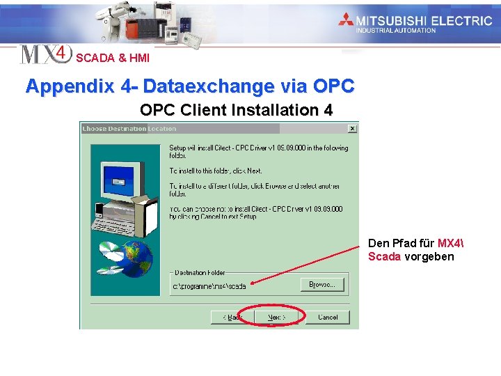
Industrial Automation SCADA & HMI Appendix 4 - Dataexchange via OPC Client Installation 4 Den Pfad für MX 4 Scada vorgeben

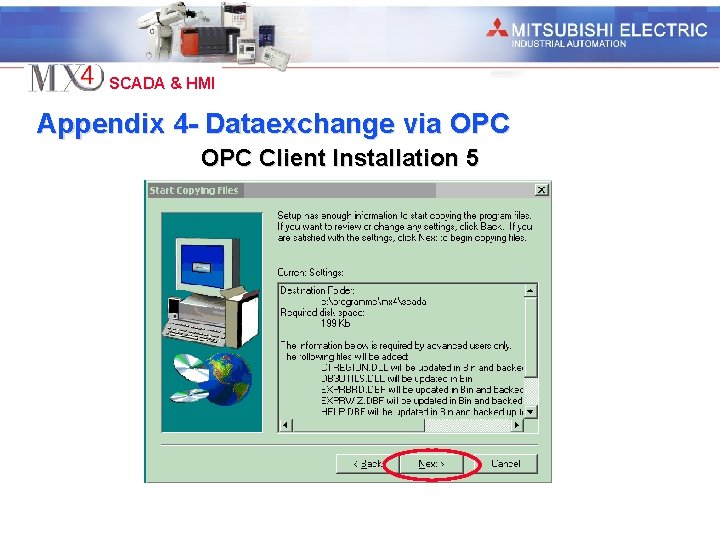
Industrial Automation SCADA & HMI Appendix 4 - Dataexchange via OPC Client Installation 5

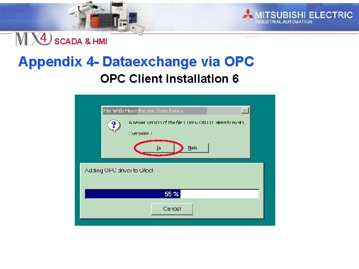
Industrial Automation SCADA & HMI Appendix 4 - Dataexchange via OPC Client Installation 6

Industrial Automation SCADA & HMI Appendix 4 - Dataexchange via OPC Client Installation 7

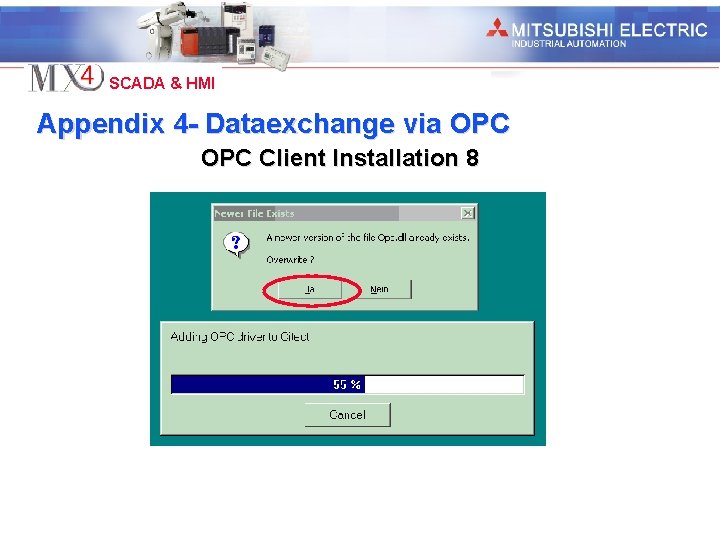
Industrial Automation SCADA & HMI Appendix 4 - Dataexchange via OPC Client Installation 8

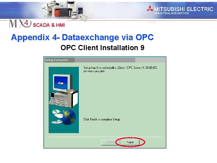
Industrial Automation SCADA & HMI Appendix 4 - Dataexchange via OPC Client Installation 9

Industrial Automation SCADA & HMI Appendix 4 - Dataexchange via OPC I/O Server configuration

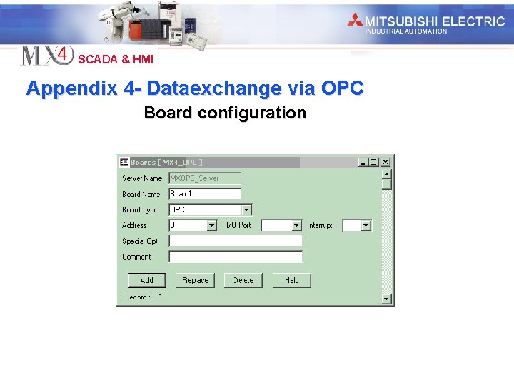
Industrial Automation SCADA & HMI Appendix 4 - Dataexchange via OPC Board configuration

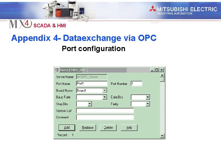
Industrial Automation SCADA & HMI Appendix 4 - Dataexchange via OPC Port configuration

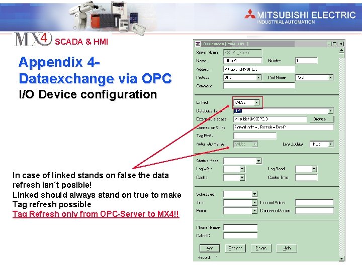
Industrial Automation SCADA & HMI Appendix 4 Dataexchange via OPC I/O Device configuration In case of linked stands on false the data refresh isn´t posible! Linked should always stand on true to make Tag refresh possible Tag Refresh only from OPC-Server to MX 4!!

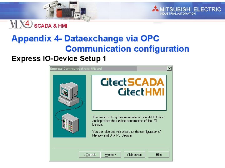
Industrial Automation SCADA & HMI Appendix 4 - Dataexchange via OPC Communication configuration Express IO-Device Setup 1

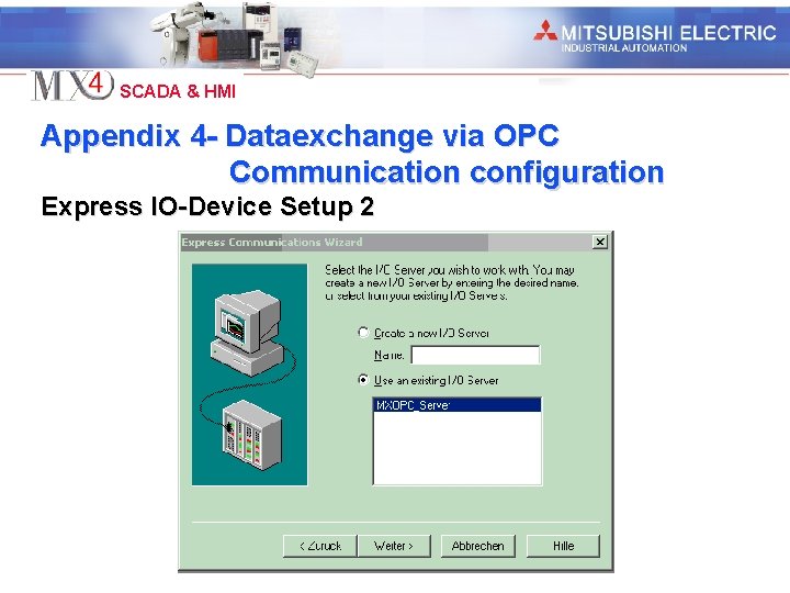
Industrial Automation SCADA & HMI Appendix 4 - Dataexchange via OPC Communication configuration Express IO-Device Setup 2

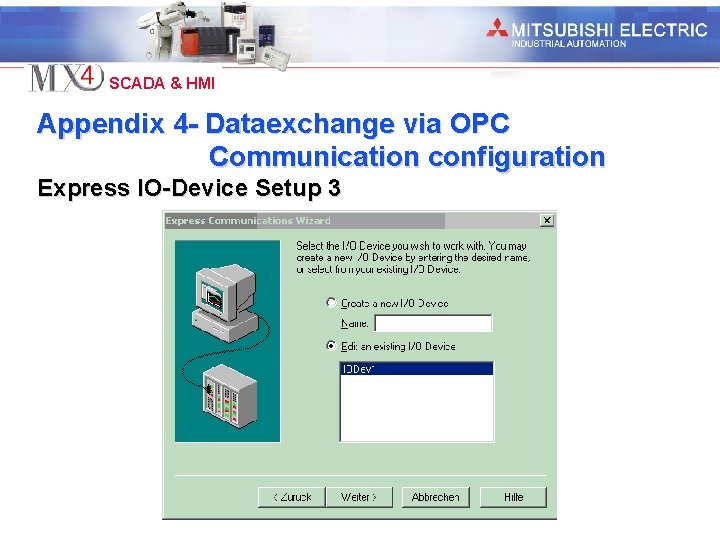
Industrial Automation SCADA & HMI Appendix 4 - Dataexchange via OPC Communication configuration Express IO-Device Setup 3

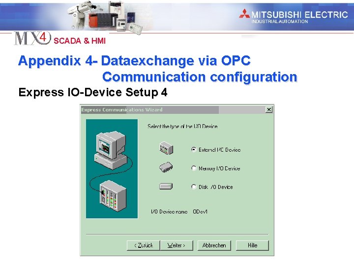
Industrial Automation SCADA & HMI Appendix 4 - Dataexchange via OPC Communication configuration Express IO-Device Setup 4

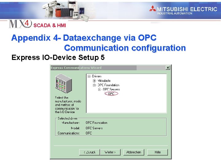
Industrial Automation SCADA & HMI Appendix 4 - Dataexchange via OPC Communication configuration Express IO-Device Setup 5

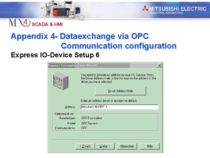
Industrial Automation SCADA & HMI Appendix 4 - Dataexchange via OPC Communication configuration Express IO-Device Setup 6

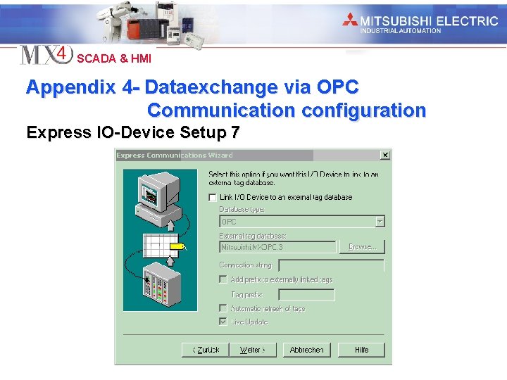
Industrial Automation SCADA & HMI Appendix 4 - Dataexchange via OPC Communication configuration Express IO-Device Setup 7

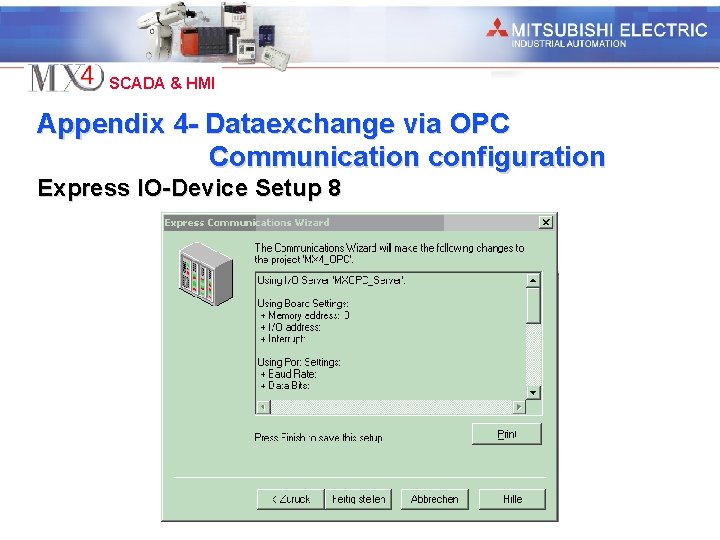
Industrial Automation SCADA & HMI Appendix 4 - Dataexchange via OPC Communication configuration Express IO-Device Setup 8